Table of Contents
Advertisement
Quick Links
For use with machines Code numbers:
This manual covers equipment which is no
longer in production by The Lincoln Electric Co.
Speci cations and availability of optional
features may have changed.
Safety Depends on You
Lincoln arc welding and cutting equipment is designed and built with safety in
mind. However, your overall safety can be increased by proper installation ... and
thoughtful operation on your part. DO NOT INSTALL, OPERATE OR REPAIR
THIS EQUIPMENT WITHOUT READING THIS MANUAL AND THE SAFETY
PRECAUTIONS CONTAINED THROUGHOUT. And, most importantly, think
before you act and be careful.
Please Examine Carton and Equipment For Damage Immediately
When this equipment is shipped, title passes to the purchaser upon receipt by
the carrier. Consequently, Claims for material damaged in shipment must be
made by the purchaser against the transportation company at the time the
shipment is received.
Please record your equipment identification information below for future refer-
ence. This information can be found on your machine nameplate.
Product ________________________
Model Number _____________________
Code Number or Date Code_________________
Serial Number_______________________
Date Purchased_______________________________
Where Purchased______________________
Whenever you request replacement parts or information on this equipment,
always supply the information you have recorded above. The code number is
especially important when identifying the correct replacement parts.
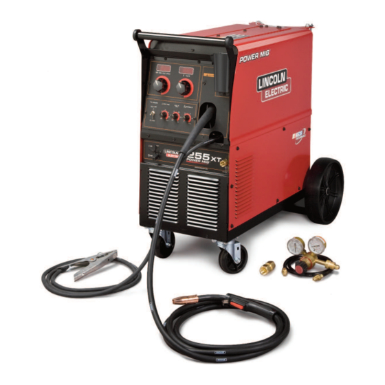
POWER MIG
11519, 11520
255XT
®
OPERATOR'S MANUAL
IMT977
Advertisement
Table of Contents

Related Manuals for Lincoln Electric POWER MIG 255XT


Summary of Contents for Lincoln Electric POWER MIG 255XT
- Page 1 For use with machines Code numbers: 11519, 11520 OPERATOR’S MANUAL This manual covers equipment which is no longer in production by The Lincoln Electric Co. Speci cations and availability of optional features may have changed. Safety Depends on You Lincoln arc welding and cutting equipment is designed and built with safety in mind.
- Page 2 SAFETY WARNING ARC WELDING CAN BE HAZARDOUS. PROTECT YOUR- SELF AND OTHERS FROM POSSIBLE SERIOUS INJURY OR DEATH. KEEP CHILDREN AWAY. PACEMAKER WEAR- ERS SHOULD CONSULT WITH THEIR DOCTOR BEFORE OPERATING. Read and understand the following safety highlights. For additional safety information, it is strongly recommended that you purchase a copy of “Safety in Welding &...
- Page 3 SAFETY WELDING SPARKS can cause fire or explosion. 4.a. Remove fire hazards from the welding area. If this is not possible, cover them to prevent the welding sparks from starting a fire. Remember that welding sparks and hot materials from welding can easily go through small cracks and openings to adjacent areas.
- Page 4 SAFETY ELECTRIC SHOCK can kill. 5.a. The electrode and work (or ground) circuits are electrically “hot” when the welder is on. Do not touch these “hot” parts with your bare skin or wet cloth- ing. Wear dry, hole-free gloves to insulate hands.
- Page 5 SAFETY FUMES AND GASES can be dangerous. 6.a.Welding may produce fumes and gases hazardous to health. Avoid breathing these fumes and gases.When welding, keep your head out of the fume. Use enough ventila- tion and/or exhaust at the arc to keep fumes and gases away from the breathing zone.
- Page 6 SAFETY CYLINDER may explode if damaged. 7.a. Use only compressed gas cylinders containing the correct shielding gas for the process used and properly operat- ing regulators designed for the gas and pressure used. All hoses, fittings, etc. should be suitable for the application and maintained in good condition.
-
Page 7: Table Of Contents
TABLE OF CONTENTS Page Installation ..............Section A Technical Specifications ..........A-1 Safety Precautions............A-2 Uncrating the POWER MIG® 255XT ......A-2 Location ................A-2 Input Power, Grounding and connection DiagramsA-2/A-4 Output polarity Connections..........A-5 Gun and Cable Installation..........A-5 Shielding Gas ............A-6,A-7 Operation ..............Section B Safety Precautions ............B-1 Product Description ............B-2 Recommended Processes and Equipment....B-2... - Page 8 TABLE OF CONTENTS Page Maintenance.............Section D Safety Precautions ............D-1 General Maintenence .............D-1 Drive Rolls and Guide Tubes..........D-1 Contact Tip and gas Nozzle Installation ......D-1 Gun Tubes and Nozzles ..........D-2 Cable Cleaning ...............D-2 Liner removal and Replacement......D-3,D-4 Gun Handle Disassembly ..........D-5 Troubleshooting ............Section E How to Use Troubleshooting Guide........E-1 Troubleshooting Guide............E-2...
-
Page 9: Technical Specifications
TECHNICAL SPECIFICATIONS INPUT – SINGLE PHASE ONLY Standard Input Current @ 200 Input Current @ 250 Voltage/Frequency Amp Rated Output Amp Rated Output *47/44 Amps 208/230/60 Hz *56/52 41/20/16 Amps 50/24/19 230/460/575/60 Hz With 115V receptacle loaded to 15A. RATED OUTPUT Volts at rated Duty Cycle Amps... -
Page 10: Safety Precautions
INSTALLATION Read entire installation section before starting installation. SAFETY PRECAUTIONS WARNING • ELECTRIC SHOCK can kill. • Only qualified personnel should perform this installation. • Only personnel that have read and understood the POWER MIG® 255XT Operating Manual should install and operate this equipment. - Page 11 INSTALLATION 1. Before starting the installation, check with the local power company if there is any question about whether your power supply is adequate for the volt- age, amperes, phase, and frequency specified on the welder nameplate. Also be sure the planned installation will meet the U.S.
- Page 12 INSTALLATION 4. Using the instructions in Figure A.3, have a quali- fied electrician connect the receptacle or cable to the input power lines and the system ground per the U.S. National Electrical Code and any applica- ble local codes. See "Technical Specifications" at the beginning of this chapter for proper wire sizes.
-
Page 13: Output Polarity Connections
INSTALLATION OUTPUT POLARITY CONNECTIONS The welder, as shipped from the factory, is connected for electrode positive (+) polarity. This is the normal polarity for GMA welding. If negative (–) polarity is required, interchange the connection of the two cables located in the wire drive compartment near the front panel. -
Page 14: Shielding Gas
INSTALLATION SHIELDING GAS (For Gas Metal Arc Welding Processes) Customer must provide cylinder of appropriate type shielding gas for the process being used. A gas flow regulator, for CO 2 or Argon blend gas, and an inlet gas hose are factory provided with the POWER MIG®... - Page 15 INSTALLATION NOTE: If connecting to 100% CO cylinder, insert regulator adapter between regulator and cylinder valve. If adapter is equipped with a plastic washer, be sure it is seated for connection to the CO cylinder. 5. Attach one end of the inlet gas hose to the outlet fitting of the flow regulator, the other end to the POWER MIG®...
-
Page 16: Operation
OPERATION Read entire Operation section before operating the POWER MIG® 255XT. WARNING ELECTRIC SHOCK can kill. • Do not touch electrically live parts or electrode with skin or wet clothing. Insulate yourself from work ground. • Always wear dry insulating gloves. -
Page 17: Product Description
OPERATION PRODUCT DESCRIPTION The POWER MIG® 255XT is a complete semiautomatic constant voltage DC arc welding machine built to meet NEMA specifications. It combines a constant voltage power source and a constant speed wire feeder with a microcomputer-based controller to form a reliable high- performance welding system. -
Page 18: Welding Capability
OPERATION WELDING CAPABILITY The POWER MIG® 255XT is rated at 250 amps @ 26 volts, at a 40% duty cycle based on a ten minute cycle time. It is capable of higher duty cycles at lower output currents and capable of up to 300 Amps at lower duty cycles. -
Page 19: Wire Size Conversion Parts
OPERATION WIRE SIZE CONVERSION PARTS The POWER MIG® 255XT is rated to feed .025 through .045" (0.6-1.2 mm) solid or cored electrode sizes. The drive roll kits and Magnum 250L gun and cable parts are available to feed different sizes and types of electrodes. - Page 20 OPERATION 1. Open the Wire Drive Compartment Door 2. Depress the Release Bar on the Retaining Collar and remove it from the spindle. 3. Place the Optional Adapter on the spindle 4. Re-install the Retaining Collar. Make sure that the Release Bar "pops up"...
-
Page 21: To Start The Welder
OPERATION To Mount 10 to 44 Lb. (4.5-20 kg) Spools (12"/300 mm Diameter) or 14Lb.(6 Kg) Innershield Coils: For 13-14 lb. (6 Kg) Innershield coils, a K435 Coil Adapter must be used). (For 10 lb.(4.5 Kg) 8 inch(203mm) diameter spools, a K468 spindle adapter must be used). -
Page 22: Idle Roll Pressure Setting
OPERATION 3. Release the pressure on the idle roll by swinging the adjustable pressure arm down toward the back of the machine. Lift the cast idle roll assembly and allow it to sit in an upright position. Leave the outer wire guide plate installed. -
Page 23: Wire Drive Configuration
OPERATION WIRE DRIVE CONFIGURATION (See Figure B.4) Changing the Gun Receiver Bushing WARNING ELECTRIC SHOCK can kill. • Turn the input power OFF at the welding power source before installation or chang- ing drive rolls and/or guides. • Do not touch electrically live parts. ••... - Page 24 OPERATION FIGURE B-4 THUMB SCREW GUN RECEIVER BUSHING OUTER WIRE GUIDE CONNRCTOR BLOCK SOCKET HEAD CAP SCREW LOOSEN TIGHTEN...
-
Page 25: Setting Run-In Speed
OPERATION SETTING RUN-IN SPEED ON STAN- DARD POWER MIG FEEDER FAST OR SLOW RUN-IN MODE SELECTION, (When Timer Option is not installed) The POWER MIG® 255XT is factory set for fast run-in mode where the wire feed will accelerate directly to the preset wire feed speed when the gun trigger is closed. -
Page 26: Operating Instructions For Timer Setting
OPERATION It is not necessary to repeat either of the above procedures each time the unit is powered up. The unit will remember the run-in mode from the previous power down and return you to that same state upon your next power up. Thus, you need only perform one of the above procedures when you want to change the run-in mode. - Page 27 OPERATION To make spot plug welds, punch 3/16" (5 mm) holes in the top sheet. Set the Spot Time control to approximately 1.2 seconds and set the procedure for the metal thickness to be welded. Install spot weld nozzle (if available) on gun and press it against the top sheet so the top and bottom sheets are tight together.
-
Page 28: Making A Weld
OPERATION MAKING A WELD 1. Check that the electrode polarity is correct for the process being used, then turn the power switch 2. Set desired arc voltage and wire speed for the particular electrode wire, material type and thickness, and gas (for GMAW) being used. Use the Application Chart on the door inside the wire compartment as a quick reference for some common welding procedures. -
Page 29: Avoiding Wire Feeding Problems
OPERATION WARNING When using an open arc process, it is necessary to use correct eye, head, and body protection. ----------------------------------------------------------------------- 8. Position electrode over joint. End of electrode may be lightly touching the work. 9. Lower welding helmet, close gun trigger, and begin welding. -
Page 30: Fan Controls
OPERATION g. Keep wire reel spindle brake tension to minimum required to prevent excess reel over-travel which may cause wire "loop-offs" from coil. h. Use proper drive rolls and wire drive idle roll pressure for wire size and type being used. FAN CONTROL The fan is designed to come on automatically when a weld arc is established. -
Page 31: Welding Thermal Overload Protection
OPERATION WELDING THERMAL OVERLOAD PROTECTION The POWER MIG® 255XT has built-in protective thermostats that respond excessive temperature. They open the wire feed and welder output circuits if the machine exceeds maximum safe operating temperature because of a frequent overload, or high ambient temperature plus overload. -
Page 32: Accessories
ACCESSORIES DRIVE ROLL KITS Refer to Table C.1 for various drive roll kits that are available for the POWER MIG. All items in Bold are supplied standard with the POWER MIG. TABLE C.1 Electrode Type Wire Size Drive Roll Kit Solid Steel .023”-.030”... -
Page 33: Alternative Magnum Gmaw Gun And Cable Assemblies
ACCESSORIES ALTERNATIVE MAGNUM GMAW GUN AND CABLE ASSEMBLIES The following Magnum 250L gun and cable assemblies are separately available for use with the POWER MIG® 255XT. Each is rated 200 amps 60% duty cycle (or 250 amps 40% duty) and is equipped with the integrated connector, twist-lock trigger connector, fixed nozzle and insulator, and includes a liner, diffuser, and contact tips for the wire sizes... -
Page 34: Spool Gun
ACCESSORIES SPOOL GUN WARNING Remove all input power to the POWER MIG® 255XT before proceeding. ----------------------------------------------------------------------------------------- The POWER MIG® 255XT provides direct connection and use of the Spool Gun (with remote speed control). It also provides gun trigger switch transfer between the machine’s use with its feeder gun or the spool gun for same polarity welding with different wire and gas processes. -
Page 35: Spool Gun Installed
ACCESSORIES FIGURE C.1 7-PIN SPOOL GUN RECEPTACLE K2445-1 CABLE ADAPTER (7-pin to 6-pin) Note: This adapter is only for The Magnum SG Spool Gun. + POSITIVE GAS LINE CABLE AND STUD AND 5/8 FITTING MAKING A WELD WITH THE SPOOL GUNS The POWER MIG control circuitry is designed to sense either the spool gun or (built in) wire feeder... -
Page 36: Magnum Sg Spool Gun
ACCESSORIES 2. Pulling SPOOL GUN Trigger: a. Disables built-in feeder gun operation. b. Closing spool gun trigger starts spool gun weld- ing and makes both electrodes electrically "HOT". 3. Operation with POWER MIG® 255XT: a. Turn the POWER MIG® 255XT input power ON. b. - Page 37 ACCESSORIES CAUTION Closing either gun trigger will cause the electrode of both guns to be electrically "HOT". Be sure unused gun is positioned so electrode or tip will not contact metal case or other metal common to work. ----------------------------------------------------------------------- 1. Pulling the trigger for the built-in feeder gun: a.
- Page 38 INSTALLATION MAGNUM 250LX PUSH-PULL GUN AND PUSH PULL ADAPTER For heavier duty aluminum applications when use of large 16 pound aluminum spools of wire are desired the following push pull gun and adapter kit are available. Magnum 250LX Push Pull Gun (K2704-1) This pistol grip push pull gun is similar to the Magnum 250LX spool gun except it is designed to feed large spools of wire.
- Page 39 MAGNUM ADAPTER 250LX ACCESSORIES CONNECTING THE MAGNUM 250 LX PUSH- PULL GUN (K2704-1) AND MAGNUM 250LX PUSH-PULL GUN ADAPTER (K2705-1) See Figure C.2 1. Plug the 115 VAC cable into available 115V AC receptacle. The POWER MIG® 255XT (K2701-1) furnishes the 15A 115V AC auxiliary supply. The receptacle is located at the back of the machine.
-
Page 40: Magnum 250Lx Push-Pull
ACCESSORIES MAKE A WELD WITH THE MAGNUM 250LX PUSH-PULL GUN 1. POWER MIG® 255XT a. Set machine to non spool gun operation. b. Turn the POWER MIG® 255XT input power ON adjusting the voltage control at the front panel. c. Adjust the wire speed control on the front panel. Refer to the procedure decal mounted at the inside of the wire feeder compartment cover. -
Page 41: Maintenance
MAINTENANCE SAFETY PRECAUTIONS WARNING ELECTRIC SHOCK can kill. • Have an electrician install and service this equipment. • Turn the input power off at the fuse box before working on equipment • Do not touch electrically hot parts. GENERAL MAINTENANCE In extremely dusty locations, dirt may clog the air passages causing the welder to run hot. -
Page 42: Gun Tubes And Nozzles
MAINTENANCE b. Screw the appropriate fixed gas nozzle fully onto the diffuser. Either the standard .50" (12.7 mm) flush nozzle or other optional flush or recessed (spray arc) nozzle sizes may be used. (See Table D.2 in this section.) c. If using optional adjustable slip-on noz-zles, see Table D.2 in this section. -
Page 43: Liner Removal And Replacement
MAINTENANCE Flex the cable over its entire length and again blow out the cable. Repeat this procedure until no further dirt comes out. If this has been done and feed prob- lems are experienced, try liner replacement, and refer to trouble shooting section on rough wire feeding. LINER REMOVAL AND REPLACE- MENT NOTE: Changing the liner for a different wire size... - Page 44 MAINTENANCE Insert a new untrimmed liner into the connector end of the cable. Be sure the liner bushing is stencilled appropriately for the wire size being used. Note: For liners KP1950-7, KP1950-8, KP1955-1 and KP1599-2 Before fully seating the liner bushing, it will be neces- sary to trim the liner’s inner tube flush with the liner bushing using a sharp blade.
-
Page 45: Gun Handle Disassembly
MAINTENANCE FIGURE D.1 TORNILLO DE FIJACION SET SCREW CONECTOR DE CABLE DE COBRE BRASS CABLE CONNECTOR 1-1/4" (31.8mm) 1-1/4 (31,8 mm) LONGITUD DE LINER TRIM CORTE LENGTH TORNILLO DE FIJACION SET SCREW DIFUSOR DE GAS GAS DIFFUSER NOZZLE INSULATOR (IF USED) AISLADOR DE TOBERA (SI SE UTILIZA) TOBERA DE GAS... - Page 46 MAINTENANCE TABLE D.2 ACCESSORIES AND EXPENDABLE REPLACE- MENT PARTS FOR MAGNUM 250L GUN AND CABLE ASSEMBLIES English Metric Description Part No. Size Size CABLE LINER For 15' KP1934-2 .025 – .030" 0.6 – 0.8 mm (4.5 m) or KP1934-1 .035 – .045" 0.9 –...
-
Page 47: Troubleshooting
TROUBLESHOOTING HOW TO USE TROUBLESHOOTING GUIDE WARNING Service and Repair should only be performed by Lincoln Electric Factory Trained Personnel. Unauthorized repairs performed on this equipment may result in danger to the technician and machine operator and will invalidate your factory warranty. For your safety and to avoid Electrical Shock, please observe all safety notes and precautions detailed throughout this manual. - Page 48 TROUBLESHOOTING Major physical or electrical damage is evident. Contact your Local Lincoln Authorized Field service facility. There is no wire feed or open circuit voltage when the gun trigger is pulled. The machine dis- plays are lit indicating input power to the POWER MIG®...
- Page 49 TROUBLESHOOTING Machine output is low. Welds are "cold", weld bead is rounded or bumped up demonstrating poor wetting into plate. 1. Check input voltage. Make sure input voltage matches name-plate rating and reconnect panel configuration. 2. Make sure settings for wire feed speed and volt- age are correct for process being used.
- Page 50 TROUBLESHOOTING Rough wire feeding or wire will not feed but drive rolls are turning. 1. The gun cable may be kinked or twisted. 2. The wire may be jammed in the gun cable, or gun cable may be dirty. 3. Check drive roll tension and position of grooves.
- Page 51 Enhanced Diagram NOTE: This diagram is for reference only. It may not be accurate for all machines covered by this manual. The specific diagram for a particular code is pasted inside the machine on one of the enclosure panels. If the diagram is illegible, write to the Service Department for a replacement. Give the equipment code number.
- Page 52 NOTE: This diagram is for reference only. It may not be accurate for all machines covered by this manual. The specific diagram for a particular code is pasted inside the machine on one of the enclosure panels. If the diagram is illegible, write to the Service Department for a replacement. Give the equipment code number.
- Page 53 DIMENSION PRINT POWER MIG® 255XT M19231 M19231...
- Page 54 Keep your head out of fumes. Do not touch electrically live parts or Keep flammable materials away. Wear eye, ear and body protection. Use ventilation or exhaust to WARNING electrode with skin or wet clothing. remove fumes from breathing zone. Insulate yourself from work and ground.
- Page 55 READ AND UNDERSTAND THE MANUFACTURER’S INSTRUCTION FOR THIS EQUIPMENT AND THE CONSUMABLES TO BE USED AND FOLLOW YOUR EMPLOYER’S SAFETY PRACTICES. Turn power off before servicing. Do not operate with panel open or guards off. WARNING Learn more about welding equipment and soldering tools we have.
Need help?
Do you have a question about the POWER MIG 255XT and is the answer not in the manual?
Questions and answers