Advertisement
Table of Contents
- 1 Table of Contents
- 2 Maintain
- 3 Hot-Swap a Disk Drive in a DS224C or DS212C Disk Shelf - Shelves with IOM12 Modules
- 4 Hot-Swap a Disk Drive in a DS460C Disk Shelf - Shelves with IOM12 Modules
- 5 Replacing a Drive Drawer in a DS460C Disk Shelf - Shelves with IOM12 Modules
- 6 Replace a Fan Module in a DS460C Disk Shelf - Shelves with IOM12 Modules
- 7 Hot-Remove a Shelf - Shelves with IOM12 Modules
- 8 Hot-Swap or Replace an IOM12 Module - Shelves with IOM12 Modules
- 9 Hot-Swap a Power Supply - Shelves with IOM12 Modules
- 10 Monitor Disk Shelf Leds - Shelves with IOM12 Modules
- Download this manual
Advertisement
Table of Contents

Related Manuals for NetApp DS224C


Summary of Contents for NetApp DS224C
- Page 1 Maintain ONTAP Systems NetApp June 27, 2022 This PDF was generated from https://docs.netapp.com/us-en/ontap-systems/sas3/service-hot-swap- drive-ds224c-ds212c.html on June 27, 2022. Always check docs.netapp.com for the latest.
-
Page 2: Table Of Contents
................ Hot-swap a disk drive in a DS224C or DS212C disk shelf - shelves with IOM12 modules .... -
Page 3: Maintain
You can hot-swap a failed disk drive in a DS224C or DS212C disk shelf. Before you begin • The disk drive that you are installing must be supported by the DS224C or DS212C disk shelf. NetApp Hardware Universe • All other components in the system must be functioning properly; if not, contact technical support. - Page 4 • The best practice is to have the current versions of disk shelf (IOM) firmware and disk drive firmware on your system before adding new disk shelves, shelf FRU components, or SAS cables. Current versions of firmware can be found on the NetApp Support Site. NetApp Downloads: Disk Shelf Firmware NetApp Downloads: Disk Drive Firmware •...
- Page 5 Disk drives in a DS212C disk shelf are arranged horizontally with the release button located on the left of the disk drive face. Disk drives in a DS224C disk shelf are arranged vertically with the release button located at the top of the disk drive face.
- Page 6 6. Slide out the disk drive slightly to allow the disk to safely spin down, and then remove the disk drive from the disk shelf. An HDD can take up to one minute to safely spin down. When handling a disk drive, always use two hands to support its weight. 7.
-
Page 7: Hot-Swap A Disk Drive In A Ds460C Disk Shelf - Shelves With Iom12 Modules
-node node_name -autoassign on You need to reenable automatic drive assignment on both controllers in an HA pair. 12. Return the failed part to NetApp, as described in the RMA instructions shipped with the kit. Contact technical support at NetApp... - Page 8 • The best practice is to have the current versions of disk shelf (IOM) firmware and disk drive firmware on your system before adding new disk shelves, shelf FRU components, or SAS cables. Current versions of firmware can be found on the NetApp Support Site. NetApp Downloads: Disk Shelf Firmware NetApp Downloads: Disk Drive Firmware •...
- Page 9 • The following illustration shows how the drives are numbered from 0 to 11 in each drive drawer within the shelf. Steps 1. If you want to manually assign disk ownership for the replacement disk drive, you need to disable automatic drive assignment if it is enabled;...
- Page 10 Save all packaging materials for use when returning the failed disk drive. NetApp requires that all returned disk drives be in a ESD-rated bag. 4. Identify the failed disk drive from the system console warning message and the illuminated amber attention LED on the drive drawer.
- Page 11 Orange release latch b. Open the cam handle, and lift out the drive slightly. c. Wait 30 seconds. d. Use the cam handle to lift the drive from the shelf.
- Page 12 e. Place the drive on an antistatic, cushioned surface away from magnetic fields. 7. Insert the replacement drive in the drawer: a. Raise the cam handle on the new drive to vertical. b. Align the two raised buttons on each side of the drive carrier with the matching gap in the drive channel on the drive drawer.
- Page 13 Raised button on the right side of the drive carrier c. Lower the drive straight down, and then rotate the cam handle down until the drive snaps into place under the orange release latch. d. Carefully push the drive drawer back into the enclosure. Possible loss of data access: Never slam the drawer shut.
-
Page 14: Replacing A Drive Drawer In A Ds460C Disk Shelf - Shelves With Iom12 Modules
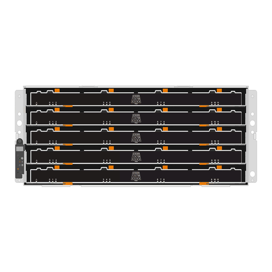
-autoassign on You need to reenable disk ownership automatic assignment on both controllers in an HA pair. 11. Return the failed part to NetApp, as described in the RMA instructions shipped with the kit. Contact technical support at NetApp... - Page 15 And each of the five drawers can hold up to 12 drives. Before you begin You need these items for this procedure: • Antistatic protection Possible hardware damage: To prevent electrostatic discharge damage to the drive shelf, use proper antistatic protection when handling drive shelf components. •...
- Page 16 Removing the cable chains Left and right cable chains for each drive drawer in the DS460C drive shelf allow the drawers to slide in and out. Before you can remove a drive drawer, you must remove both cable chains. Before you begin •...
- Page 17 Fan module handle b. Using the handle, pull the fan module out of the drive shelf, and set it aside. 3. Manually determine which of the five cable chains to disconnect. The figure shows the right side of the drive shelf with the fan module removed. With the fan module removed, you can see the five cable chains and the vertical and horizontal connectors for each drawer.
- Page 19 Cable chain Vertical connector (connected to the midplane) Horizontal connector (connected to the drive drawer) The top cable chain is attached to drive drawer 1. The bottom cable chain is attached to drive drawer 5. 4. Use your finger to move the cable chain on the right side to the left. 5.
- Page 20 Orange ring on the vertical bracket b. Disconnect the vertical connector (connected to the midplane) by gently pressing on the center of the...
- Page 21 orange ring and pulling the left side of the cable out of the enclosure. c. To unplug the cable chain, carefully pull your finger toward you approximately 1 inch (2.5 cm), but leave the cable chain connector within the vertical bracket. 6.
- Page 22 Orange ring on horizontal bracket Cable chain...
- Page 23 b. Gently insert your finger into the orange ring. The figure shows the orange ring on the horizontal bracket being pushed down so that the rest of the cable chain can be pulled out of the enclosure. c. Pull your finger toward you to unplug the cable chain. 7.
- Page 24 b. Raise the drive handle to vertical. c. Use the handle to lift the drive from the drive drawer.
- Page 25 d. Place the drive on a flat, static-free surface and away from magnetic devices. Possible loss of data access: Magnetic fields can destroy all data on the drive and cause irreparable damage to the drive circuitry. To avoid loss of data access and damage to the drives, always keep drives away from magnetic devices.
- Page 26 c. While holding both release levers, pull the drive drawer toward you. d. Remove the drive drawer from the drive shelf. Installing a drive drawer Installing a drive drawer into a drive shelf entails sliding the drawer into the empty slot, installing the drives, and replacing the front bezel.
- Page 27 Positioning the drawer slightly to the right of center helps to ensure that the lock-out tumbler and the drawer guide are correctly engaged. 3. Slide the drive drawer into the slot, and ensure that the drawer guide slides under the lock-out tumbler. Risk of equipment damage: Damage occurs if the drawer guide does not slide under the lock-out tumbler.
- Page 28 Raised button on the right side of the drive. e. Lower the drive straight down, and then rotate the drive handle down until the drive snaps into place. If you have a partially populated shelf, meaning that the drawer in which you are reinstalling drives has less than the 12 drives it supports, install the first four drives into the front slots (0, 3, 6, and 9).
- Page 29 f. Repeat these substeps to reinstall all of the drives. 6. Slide the drawer back into the drive shelf by pushing it from the center and closing both levers. Risk of equipment malfunction: Make sure to completely close the drive drawer by pushing both levers.
- Page 30 Callout Cable chain Connector Connects to Left Vertical Midplane Left Horizontal Drive drawer...
- Page 31 Callout Cable chain Connector Connects to Right Horizontal Drive drawer Right Vertical Midplane Steps 1. Follow these steps to attach the left cable chain: a. Locate the horizontal and vertical connectors on the left cable chain and the corresponding horizontal and vertical brackets inside the enclosure.
- Page 32 Guide rail...
-
Page 33: Replace A Fan Module In A Ds460C Disk Shelf - Shelves With Iom12 Modules
Risk of equipment malfunction: Make sure to slide the connector underneath the guide rail on the bracket. If the connector rests on the top of the guide rail, problems might occur when the system runs. d. Slide the vertical connector on the left cable chain into the vertical bracket. e. - Page 34 Steps 1. Put on antistatic protection. 2. Unpack the new fan module, and place it on a level surface near the shelf. Save all packing material for use when returning the failed fan. 3. From the back of the disk shelf, look at the Attention LEDs to locate the fan module you need to remove. You must replace the fan module that has its Attention LED on.
- Page 35 Tab that you press to release the fan module handle 5. Use the fan module handle to pull the fan module out of the shelf.
-
Page 36: Hot-Remove A Shelf - Shelves With Iom12 Modules
The LED goes off after this process is complete. 8. Return the failed part to NetApp, as described in the RMA instructions shipped with the kit. Contact technical support at NetApp Support, 888-463-8277 (North America), 00-800-44-638277 (Europe), or +800-800-80-800 (Asia/Pacific) if you need the RMA number. - Page 37 You can download and run Active IQ Config Advisor to view any SAS cabling error messages and the corrective actions you should take. NetApp Downloads: Config Advisor • HA pair configurations cannot be in a takeover state. • You must have removed all aggregates from the disk drives (the disk drives must be spares) in the disk shelves you are removing.
- Page 38 2. Determine which node holds epsilon: cluster show The node that holds epsilon shows in the column. (The nodes that do not hold epsilon true Epsilon show false.) 3. If the node in the HA pair that is undergoing maintenance shows (holds epsilon), then remove true epsilon from the node:...
- Page 39 If you have failed disk drives in the shelf you are removing, they have broken in the column. (Failed disk drive do not have ownership.) Container Type The following output shows disk drives on the disk shelf being removed (disk shelf 3) are in a correct state for removing the disk shelf.
- Page 40 Note the following about the cabling examples: ◦ The IOM12 modules are arranged side-by-side as in a DS224C or DS212C disk shelf; if you have a DS460C, the IOM12 modules are arranged one above the other.
- Page 41 6. Verify that you bypassed the disk shelves you are removing and reestablished the path A (IOM A) stack connections correctly: storage disk show -port For HA pair configurations, you run this command from the clustershell of either controller. It might take up to a minute for the system to complete discovery.
- Page 42 If the output shows… Then… All disk drives in the stack are connected through Go to the next step. path A and path B except for the ones in the disk You successfully bypassed the disk shelves you are shelves you disconnected, which are only removing and reestablished path A on the connected through path B remaining disk drives in the stack.
- Page 43 If you are moving the DS460C shelf to a different part of the data center or transporting it to a different location, see the following section, Move or transport DS460C shelves. Move or transport DS460C shelves If you move a DS460C shelf to a different part of the data center or transport the shelf to a different location, you need to remove the drives from the drive drawers to avoid possible damage to the drive drawers and drives.
-
Page 44: Hot-Swap Or Replace An Iom12 Module - Shelves With Iom12 Modules
• The best practice is to have the current versions of disk shelf (IOM) firmware and disk drive firmware on your system before adding new disk shelves, shelf FRU components, or SAS cables. Current versions of firmware can be found on the NetApp Support Site. NetApp Downloads: Disk Shelf Firmware NetApp Downloads: Disk Drive Firmware •... - Page 45 Save all packaging materials for use when returning the failed IOM12 module. 3. Physically identify the failed IOM12 module from the system console warning message and the illuminated attention (amber) LED on the failed IOM12 module. 4. Perform one of the following actions based on the type of configuration you have: If you have a…...
- Page 46 For each module port that you cabled, the LNK (green) LED illuminates when one or more of the four SAS lanes have established a link (with either an adapter or another disk shelf). 14. Return the failed part to NetApp, as described in the RMA instructions shipped with the kit.
-
Page 47: Hot-Swap A Power Supply - Shelves With Iom12 Modules
Hot-swap a power supply - shelves with IOM12 modules You can hot-swap a failed power supply in a DS460C, DS224C, or DS212C disk shelf. Before you begin All other components in the system—including the other power supply—must be functioning properly. - Page 48 6. Use the cam handle to slide the power supply out of the disk shelf. If you have a DS224C or DS212C disk shelf, as you remove the power supply, a flap swings into place to block the empty bay, helping to maintain air flow and cooling.
-
Page 49: Monitor Disk Shelf Leds - Shelves With Iom12 Modules
The LEDs on the disk shelf front operator display panel indicate whether your disk shelf is functioning normally or there are problems with the hardware. The following table describes the three LEDs on the operator display panel used in DS460C, DS224C, and DS212C disk shelves:... - Page 50 Depending on your disk shelf model, the operator display panel looks different; however, the three LEDs are arranged in the same way. The following illustration is of a DS224C disk shelf operator display panel with the end cap on: IOM12 module LEDs The LEDs on the IOM12 module indicate whether the module is functioning normally, whether it is ready for I/O traffic, and whether there are any problems with the hardware.
- Page 51 LED icon LED name State Description Attention Solid amber IOM12 module function: An error occurred with the function of the IOM12 module. SAS port function: Less than all four SAS lanes established a link (with either an adapter or another disk shelf). Check event messages to determine corrective action to take.
- Page 52 The following table describes the two LEDs on power supplies used in DS460C, DS224C, and DS212C disk shelves: LED icon LED name State Description Power Solid green The power supply is functioning correctly. The power supply failed,...
- Page 53 Fan LEDs on DS460C disk shelves The LEDs on the DS460C fans indicate whether the fan is functioning normally or there are hardware problems. The following table describes the LEDs on fans used in DS460C disk shelves: Item LED name State Description Attention...
- Page 54 The LEDs on a disk drive indicates whether it is functioning normally or there are problems with the hardware. Disk drive LEDs for DS224C and DS212C disk shelves The following table describes the two LEDs on the disk drives used in DS224C and DS212C disk shelves: Callout LED name...
- Page 55 Depending on your disk shelf model, disk drives are arranged vertically or horizontally in the disk shelf, dictating the location of the two LEDs. The following illustration is for a disk drive used in a DS224C disk shelf. DS224C disk shelves use 2.5-inch disk drives arranged vertically in the disk shelf.
- Page 56 Disk drive LEDs for DS460C disk shelves The following illustration and table describes the drive activity LEDs on the drive drawer and their operational states: Location Status indicator Description Attention: Drawer Solid amber A component within the attention for each drawer drive drawer requires operator attention.
- Page 57 Attention LED light on...
- Page 58 NetApp. The use or purchase of this product does not convey a license under any patent rights, trademark rights, or any other intellectual property rights of NetApp.
Need help?
Do you have a question about the DS224C and is the answer not in the manual?
Questions and answers