Table of Contents
Advertisement
Quick Links
Advertisement
Table of Contents

Related Manuals for WaterSoft CD24


Summary of Contents for WaterSoft CD24
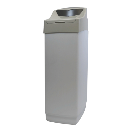
- Page 1 Cabinet Softener Manual Installation / Operation Manual...
-
Page 2: Table Of Contents
Softener Specifications............... Page 3 Softener Installation................Page 5 Start Up Procedure................Page 10 Master Programming................Page 13 Utilizing Bluetooth................Page 14 Powerhead Assembly................Page 17 Valve Body Assembly................Page 18 Cabinet Body Assembly............... Page 19 Bypass Assembly.................. Page 20 Additional Information................ Page 21 Troubleshooting................... -
Page 3: Softener Specifications
Softener Specifications General Specifications CD24 CD32 Grains Capacity / Lbs Salt Used* per regeneration 20,000 / 7.5 27,000 / 9 Maximum Raw Water Hardness (grains) Maximum Clear Iron / Manganese (ppm) Exchange Resin (cu ft ) Mineral Tank (polyglass) 9 x 35... - Page 4 Softener Specifications PLEASE NOTE THESE SPECIFICATIONS BEFORE PROCEEDING OPERATING PRESSURE RANGE : 20 - 125 PSI OPERATING TEMPERATURE RANGE : 33º F - 120º F INLET / OUTLET PIPE SIZE : 3/4: FNPT PLEASE COMPLY WITH ALL APPLICABLE PLUMBING CODES PROTECT THE SOFTENER AND PIPING FROM FREEZING TEMPERATURES Please read the entire Owner’s Manual and Instruction before installation.
-
Page 5: Softener Installation
Installation -Pre-Installation Check List- A water test should always be performed in order to determine total water hardness (in gpg) and total dissolved iron (in parts per million - ppm). This is critical for proper equipment selection, sizing and for determining the program for regeneration frequency. - Page 6 Installation Removal of Top Cabinet Lid PUSH CLIPS...
- Page 7 Installation -Softener Location / Other Requirements- • Locate the unit near an unswitched, 120 volt / 60 Hz grounded electrical outlet. • Check for distance and proper drain installation (e.g. floor drain, washing machine standpipe). • Determine type and size of piping required for softener connection (e.g. copper, galvanized, PVC plastic). Note •...
- Page 8 Installation - Drain Line Connection - 1. The drain line flow control assembly is pre-assembled for your convenience. Should you choose to hard plumb the drain line, please remove the barb fitting. The flow control housing can be removed by remov ing the clip and pulling straight out on housing.
- Page 9 Installation - Pressurizing The System - 1. Make certain the Control Valve is in SERVICE position. 2. Slowly rotate bypass valve to the SERVICE position. (Position of bypass lever is parallel to inlet / outlet piping.) 3. Open the nearest faucet to evacuate air from plumbing lines. 4.
-
Page 10: Start Up Procedure
Start Up Procedure 1. Set time of day. 2. Set a.m. or p.m. 3. Set water hardness in grains per gallon (gpg). Note : If the water contains iron and / or manganese, multiply the total parts per million (ppm) by “four” (4) and then add to the grains per gallon (gpg) of hardness. - Page 11 Start Up Procedure - Final Check - 1. Be certain the bypass valve is in the SERVICE position. 2. Make sure the power supply is connected to an uninterrupted 115-volt outlet. 3. Check that the time of day is set 4.
- Page 12 Start Up Procedure Normal Operation 1. Home Display The RS1 model will alternate the Time of Day and Gallons left until the next regeneration. The me ter will count down to zero (0000) and then regenerate at the scheduled time set. Starting Extra Regeneration Cycle 1.
-
Page 13: Master Programming
Master Programming Mode Master Programming Mode To enter Master Programming Mode, press and hold both buttons for 5 seconds. Note: All Master Programming functions have been preset at the factory. Unless a change is desired, it is NOT necessary to enter Master Programming Mode. 1. -
Page 14: Utilizing Bluetooth
Utilizing Bluetooth Control For simplified set up and control, please install the Legacy View on a compatible Bluetooth 4.0+ enabled smart phone or tablet. 1. Download and install the Legacy View app from the Google Play Store, Apple App Store 2. - Page 15 Set Up Utilizing Bluetooth App Change Time of Day (Press “SET” to set time automatically based on device). For Filters: Set Backwash Frequency This sets the amount of day between backwash cycles Set Regeneration Time Example: For 2a.m., just type 2, choose a.m., and press ‘OK’ Note: If you have a filter and a softener the valves should be set to re- generate at different times.
- Page 16 Set Up Utilizing Bluetooth App Status and History From the Status and History, all items in ORANGE can be reset. Pressing this icon will show a list of the data that is in the graph. Touch any graph to enlarge and see details.
-
Page 17: Powerhead Assembly
Powerhead Assy. Part No. 20016X002 20001X007 20016X101 21001X120 20016X002 20016X006 Motor Power Flow Meter 20001X122 SC10 20001X127 20016X108 Motor Power Flow Meter Description Part Number Front Plate 20016X001 Encoder Wheel 20001X007 Cabinet Legacy Board Assembly 20016X101 Main Gear 21001X120 Back Plate 20016X002 Motor Assy. -
Page 18: Valve Body Assembly
Valve Body Assembly 22/23 DESCRIPTION PART NO. DESCRIPTION PART NO. Piston Assembly 20001X231 Injector Cap Screw 20001X226 Screw 20001X001 Injector Cap 20001X223 Injector Seal 20001X224 Seal & Spacer Kit 20561X253 Bottom Spacer Injector - White 20017X219 DLFC Button 2.0 20251X267 Screen 20001X222 Plug... -
Page 19: Cabinet Body Assembly
Cabinet Body Assembly DESCRIPTION PART NO. Cabinet Tank Base 20016X007 Resin Tank 30935X000 Brine Well Assembly 20016X008 Cabinet Cap 20016X009 Cabinet Lid 20016X010 Top Insert 20018X008 Front Insert 20018X009 Clear 3/8” Tubing, .5ft 57005X002 Self Threading Screw 20016X015 Grid Plate 40450X106... -
Page 20: Bypass Assembly
Bypass Assembly D15 Bypass 1 20017X283 2 20017X284 1" NPT 90° Elbow Set DESCRIPTION PART NO. 20017X283 D15 Bypass 20017X284 1” NPT 90 ° Elbow Set... -
Page 21: Additional Information
Service Instructions / Instructional Videos Available at www.watersoftinc.com General Preliminary Instructions PERFORM BEFORE ALL SERVICING OPERATIONS 1. Turn off water supply to conditioner. -If the conditioner installation has a “three valve” bypass system, first open the valve in the bypass line, then close the valves at the conditioner inlet and outlet. -If the conditioner has an integral bypass valve, put it in the bypass position. - Page 22 Service Instructions / Instructional Videos Available at www.watersoftinc.com To Replace Piston Assembly 1. Follow steps A1 - A3 2. Remove control valve cover. Disconnect the meter signal wire from the meter. 3. Remove screw and washer at piston drive yoke. Remove powerhead mounting screws. The entire powerhead assembly will now lift off easily.
-
Page 23: Troubleshooting
Troubleshooting Guide SYMPTOM PROBABLE CAUSE CORRECTION Power supply plugged into Connect to constant power source intermittent or dead power source 1.Softener Fails to Disconnected meter cable Reconnect cable Regenerate Improper control valve Reset program settings Automatically programming Defective power supply Replace power supply Meter is dirty or defective Clean or replace meter assembly... - Page 24 Troubleshooting Guide SYMPTOM PROBABLE CAUSE CORRECTION 6. Loss of Water Scaling / fouling of inlet pipe Clean or replace pipeline. Pretreat to prevent. Pressure Fouled resin Clean resin. Pretreat to prevent. Improper backwash setting Backwash more frequently Plugged drain line or drain line control Check flow to drain.
-
Page 25: Error Codes
Error Codes Control Valve Error Code Diagnosis Under normal operating conditions, when your control valve is in the “in service” position, the display should alternate between the current time of day and the number of days remaining (for filters and time clock softeners) or gallons remaining (for metered softeners) until the next regeneration. - Page 26 Error Codes No Display If your display is blank, there is no power going to the circuit board due to one of the following factors: • The electrical outlet is not powered or is switched off • The power cable has come unplugged from the circuit board •...
-
Page 27: Warranty
THE PRODUCT. IN NO CASE SHALL WATERSOFT OR SELLER BE LIABLE FOR ANY SPECIAL, INCIDENTAL, CONTINGENT OR WATERSOFT will at its option either make repairs to correct any CONSEQUENTIAL DAMAGES. Special, incidental, contingent and defect in material or workmanship or supply and ship either new or consequential damages for which WATERSOFT is not liable include, used replacement parts or products. - Page 28 710 Orange Street, Ashland, OH 44805 PH 419.289.1500 FAX 419.289.1515 0622TV www.watersoftinc.com...
Need help?
Do you have a question about the CD24 and is the answer not in the manual?
Questions and answers