Table of Contents
Advertisement
Advertisement
Table of Contents

Related Manuals for WaterSoft ISOBAR III


Summary of Contents for WaterSoft ISOBAR III
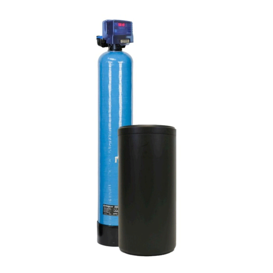
- Page 1 High Capacity Softener Manual Installation / Operation Manual...
-
Page 2: Table Of Contents
Softener Specifications............Page 3 Softener Installation..............Page 5 Programming the Control Valve..........Page 12 Master Programming............... Page 14 Utilizing Bluetooth..............Page 15 Control Valve Powerhead Assy. ISO III........Page 18 Valve Body Assembly ISO III........... Page 19 Bypass Assembly ISO III............Page 21 Service Instructions.............. -
Page 3: Softener Specifications
Softener Specifications General Specifications General Specifications HD33-3 HD51-3 HD68-3 Grains Capacity - Regeneration / Lbs Salt Used ** 35,000 / 15 52,000 / 24 70,000 / 30 Maximum Raw Water Hardness (grains) Maximum Clear Iron / Manganese Exchange Resin (cu ft per tank) Mineral Tank Size 9 x 48 10 x 54... - Page 4 Softener Specifications PLEASE NOTE THESE SPECIFICATIONS BEFORE PROCEEDING OPERATING PRESSURE RANGE : 20 - 125 PSI OPERATING TEMPERATURE RANGE : 33º F - 120º F INLET / OUTLET PIPE SIZE : 3/4: FNPT PLEASE COMPLY WITH ALL APPLICABLE PLUMBING CODES PROTECT THE SOFTENER AND PIPING FROM FREEZING TEMPERATURES Please read the entire Owner’s Manual and Instruction before installation.
-
Page 5: Softener Installation
Installation -Pre-Installation Check List- A water test should always be performed in order to determine total water hardness (in gpg) and total dissolved iron (in parts per million - ppm). This is critical for proper equipment selection, sizing and for determining the program for regeneration frequency. - Page 6 Installation -Softener Location / Other Requirements- • Locate the unit near an unswitched, 120 volt / 60 Hz grounded electrical outlet. • Check for distance and proper drain installation (e.g. floor drain, washing machine standpipe). • Determine type and size of piping required for softener connection (e.g. copper, galvanized, PVC plastic). Note •...
- Page 7 Installation -Installation Procedure- - Water Supply Connections and Bypass Valve - To allow for softener servicing, swimming pool filling or lawn sprinkling, a manual bypass valve has been installed at the factory. The bypass allows hard water to be manually routed around the softener. 1.
- Page 8 Installation - Drain Line Connection - 1. The drain line flow control assembly is pre-assembled for your convenience. Should you choose to hard plumb the drain line, please remove the barb fitting. The flow control housing can be removed by remov ing the clip and pulling straight out on housing.
- Page 9 Installation - Electrical Connection - 1. Connect the power cord and plug power supply into a 115 volt / 60 Hz receptacle. Note: Do not plug into an outlet controlled by a wall switch or pull chain that could inadvertently be turned Electronic Connections P = Power Supply B = Powered in Backwash Step Only (Cycle #1)
- Page 10 Installation Note: Salt settings are pre-set at the factory for the maximum shown on the capacity charts. Warning: Do not reduce salt settings below 9 lbs. as the water level in the brine tank will not reach the grid plate. - Control Valve Operation - 1.
- Page 11 Installation - Final Check - 1. Be certain the bypass valve is in the SERVICE position. 2. Make sure the power supply is connected to an uninterrupted 115-volt outlet. 3. Check that the time of day is set 4. Double check regeneration schedule. 5.
-
Page 12: Programming The Control Valve
Programming the Control Valve - Programming The Control Valve - 1. Set time of day. 2. Set a.m. or p.m. 3. Set Hardness (grains per gallon). Note: Salt settings are pre-set at the factory for the maximum shown on the capacity charts. Warning: Do not reduce salt settings below 9 lbs. - Page 13 Programming the Control Valve Normal Operation 1. Home Display a. Time Clock Softeners -Alternates between the display of Time of Day and Number of Days until the Next Regeneration. - Days Remaining until the Next Regeneration will count down from the entered value until it reaches 1 day remaining.
-
Page 14: Master Programming
Master Programming Mode Master Programming Mode To enter Master Programming Mode, press and hold both buttons for 5 seconds. Note: All Master Programming functions have been preset at the factory. Unless a change is desired, it is NOT necessary to enter Master Programming Mode. 1. -
Page 15: Utilizing Bluetooth
Utilizing Bluetooth Control For simplified set up and control, please install the Legacy View on a compatible Bluetooth 4.0+ enabled smart phone or tablet. 1. Download and install the Legacy View app from the Google Play Store, Apple App Store 2. - Page 16 Set Up Utilizing Bluetooth App Change Time of Day (Press “SET” to set time automatically based on device). For Filters: Set Backwash Frequency This sets the amount of day between backwash cycles Set Regeneration Time Example: For 2a.m., just type 2, choose a.m., and press ‘OK’ Note: If you have a filter and a softener the valves should be set to re generate at different times.
- Page 17 Set Up Utilizing Bluetooth App Status and History From the Status and History, all items in ORANGE can be reset. Pressing this icon will show a list of the data that is in the graph. Touch any graph to enlarge and see details.
-
Page 18: Control Valve Powerhead Assy. Iso
Control Valve Assembly LETTERS IN DIAGRAM REPRESENT WIRING CONNECTIONS DESCRIPTION PART NO. Metered Power Head Assy. 20943C100 Softener Circuit Boad Assy. 20943C102 Encoder 20001X124 Front Plate 20001X004 Encoder Wheel 20001X007 Main Gear 21001X120 Power Supply 20001X125 Back Plate 20001X005 Lower Front Base For Cover 20111X002 Legacy View Motor Assy. -
Page 19: Valve Body Assembly Iso
Valve Body Assy. (Softener Version) - Page 20 Valve Body Assy. (Softener Version) DESCRIPTION PART NO. Piston Assembly 20001X231 10-24 X 3/4” Screw SST 20001X001 Seal and Spacer Kit 20561X253 End Spacer Flow Control Button 1.5 20251X266 Flow Control Button 2.0 20251X267 Flow Control Button 2.4 20251X268 DLFC Assy. 20017X100 90 Degree Hose Barb Elbow 20017X266...
-
Page 21: Bypass Assembly Iso
Bypass Assembly DESCRIPTION PART NO. D15 Bypass (included with all units) 20017X283 1” NPT Elbow Set (included with all units) 20017X284 1” Female Straight Slip Set (optional) 20017X288 1” NPT Straight Set (optional) 20017X289 3/4” NPT Straight Set (optional) 20017X307 3/4”... -
Page 22: Service Instructions
Service Instructions / Instructional Videos Available at www.watersoftinc.com General Preliminary Instructions PERFORM BEFORE ALL SERVICING OPERATIONS 1. Turn off water supply to conditioner. -If the conditioner installation has a “three valve” bypass system, first open the valve in the by pass line, then close the valves at the conditioner inlet and outlet. - Page 23 Service Instructions / Instructional Videos Available at www.watersoftinc.com To Service Injector and Screen 1. Follow steps A1-A2. 2. Unscrew injector cover screws and remove injector cover. 3. Remove injector screen and clean or replace. 4. Remove injector and clean or replace. 5.
-
Page 24: Troubleshooting
Troubleshooting Guide SYMPTOM PROBABLE CAUSE CORRECTION Power supply plugged into Connect to constant power source intermittent or dead power source 1.Softener Fails to Disconnected meter cable Reconnect cable Regenerate Improper control valve Reset program settings Automatically programming Defective power supply Replace power supply Meter is dirty or defective Clean or replace meter assembly... - Page 25 Troubleshooting Guide SYMPTOM PROBABLE CAUSE CORRECTION Scaling / fouling of inlet pipe Clean or replace pipeline. Pretreat to prevent. 6. Loss of Water Fouled resin Clean resin. Pretreat to prevent. Pressure Improper backwash setting Backwash more frequently Plugged drain line or drain line Check flow to drain.
-
Page 26: Error Codes
Error Codes Control Valve Error Code Diagnosis Under normal operating conditions, when your control valve is in the “in service” position, the display should alter- nate between the current time of day and the number of days remaining (for filters and time clock softeners) or gallons remaining (for metered softeners) until the next regeneration. - Page 27 Error Codes No Display If your display is blank, there is no power going to the circuit board due to one of the following factors: • The electrical outlet is not powered or is switched off • The power cable has come unplugged from the circuit board •...
-
Page 28: Warranty Information
THE PRODUCT. IN NO CASE SHALL WATERSOFT OR SELLER BE LIABLE FOR ANY SPECIAL, INCIDENTAL, CONTINGENT OR WATERSOFT will at its option either make repairs to correct any CONSEQUENTIAL DAMAGES. Special, incidental, contingent and defect in material or workmanship or supply and ship either new or consequential damages for which WATERSOFT is not liable include, used replacement parts or products.
Need help?
Do you have a question about the ISOBAR III and is the answer not in the manual?
Questions and answers