Advertisement
Quick Links
EWE351PX-DWX5
EWE451PX-DWX5
EN
ELECTRIC WATER HEATER
USER MANUAL
3. ELECTRIC WATER HEATER UNIT INSTALLATION
ELECTRIC WATER HEATER
SHOWER SET INSTALLATION DIAGRAM
UNIT INSTALLATION DIAGRAM
BRACKET ACCESSORIES
Shower
Holder
Cover
Shower
Screw
Head
178mm
Shower
Holder
PVC Hose
139mm
connect to
Washer
water inlet
connection
OFF
connect to
3 in 1
Screw
water outlet
stop valve
A
connection
inlet
Fig. 3
Fig. 2
3.1 Select a suitable position in the bathroom.
3.2 Remove the screw (A) at the bottom of the Electric Water Heater . (Fig. 2)
3.3 Remove the Front Cover from the bottom and then lift up the front cover.
3.4 Mark 3 Screw points of the Heater Base on the wall. The Electric Water Heater position should be
1.5m above the bathroom floor. (Fig. 2)
3.5. Open the Shower Holder cover, mark 2 screw point of the Shower Holder beside the Electric Water Heater.
It is recommended that the top of the portion is in level the top Electric Water Heater. After screw the Shower
Holder, put back the shower holder cover.
3.6 Use 6mm diameter drill and make the wall plug holes in depth of 34mm, for mount the Electric
Water Heater.
3.7 Insert the wall plugs and mount the Electric Water Heater firmly in position with the screws provided.
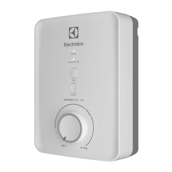
1. PARTS IDENTIFICATION
7
REV0
8
9
Fig. 1
1.
Front Cover
2.
LED Indicators
i) Earth LED Indicator
ii) Power/ELCB LED Indicator
3.
Test / Reset Button
4.
Temperature Control Knob
5.
3 in 1 Stop
Valve
i) Stop
Valve
Lever
ii) Flow Regulator Valve
Adjustment
iii) Built-in-Filter
6.
Mesh Filter
PLUMBING PROCEDURE
4.
CAUTION!
This Electric Water Heater is a single point
system and the "Water Outlet" can only be
fitted to the Hose and Handshower set
provided. NO CONTROL VALVE OF
FITTING CAN BE FITTED TO THE WATER
OUTLET.
4.1 Connect the 3 in 1 Stop Valve to the Water
Inlet with washer. Use correct tools to tighten
and be careful not to over tighten and damage
the plastic nut.
4.2 Connect the incoming water piping to the 3 in
1 Stop Valve (1/2" BSP).
Make sure to put the Mesh Filter between 3
in 1 Stop Valve and incoming water piping.
4.3 If in any case, the 3 in 1 Stop Valve is not use or
omitted, make sure to put the Mesh Filter
between the Electric Water Heater inlet pipe
and incoming water pipe.
4.4 Turn on the water mains to drain out all plumbing
dirts before connecting the water supply to the
Electric Water Heater, the water supply to the
Electric Water Heater must be free from mud and
dirt.
5. ELECTRICAL INSTALLATION
WARNING!
5.1 This Electric Water Heater must be
earthed. Improper grounding could cause
electrical shock.
5.2 Remember to SWITCH OFF the power
supply before carrying out any electrical work.
5.3 Refer to TABLE 1 for the correct cable size.
5.4 Use double insulation cable of over 2.5mm²
for 2.4kW, 3.5kW 3.8kW, 4.5kW 4.8kW models
and 4mm² for 3.6kW and 6.0kW model.
5.5 Lead the power cable from MCB to a
"ON/OFF'' double pole Linked Switch having a
contact separation of at least 3mm in all poles
outside the bathroom, then lead a cable to the
terminal block inside the Electric Water Heater.
(Fig. 4)
PROCEDURE :
5.6 Insert the wall embedded cable through
Side Entry 'A' by cutting a hole at the source
cord rubber holder and lead the cable to
3
Cable Bracket 'B'. (Fig. 6)
1
16
10
11
2
17
12
3
13
18
4
14
19
15
20
5
5
OFF
OFF
6
6
7.
Handshower
18.
TRIAC
8.
Shower Bracket Holder
19.
Reed Switch Assy
9.
PVC Hose
20.
Water Inlet Connection
10.
Heater Base
11.
Thermostat
12.
Heater Tank
13.
PCB Board (Test & Reset)
14.
Main PCB Board
15.
Water Outlet Connection
16.
Terminal Block
17.
ELCB Board
1
Always KEEP the water supply to the Electric Water
Heater free from mud and dirt at all time during usage.
IMPORTANT
THE HEATER TANK MUST BE FILLED UP WITH
WATER BEFORE TURNING ON THE POWER
SUPPLY TO PREVENT ANY DRY BURNT DAMAGE
TO THE HEATING ELEMENT.
4.5 Connect the Hose and Handshower to the
outlet of Electric Water Heater, be sure to put in the
Washer in between the connection. (Fig. 2)
4.6 Hook the Handshower to the Slider Rail
Shower Holder and adjust to your ideal position.
4.7 Check if any water leakage.
4.8 Do not use sealing tape during piping
installation.
WARNING!
4.9 THE WATER INLET AND OUTLET MUST BE
INSTALLED CORRECTLY, OTHERWISE ELECTRIC
WATER HEATER WILL NOT FUNCTION.
4.10 DO NOT APPLY PLUMBING CEMENT ON
CONNECTION. WHENEVER NECESSARY, USE
ONLY THREAD OR SEALING TAPE.
5.7 Connect the cable as following: (Fig. 5)
BROWN or RED
--LINE (L)
BLUE or BLACK
--NEUTRAL (N)
GREEN or GREEN/YELLOW --EARTH (
)
5.8 Clamp the cable to the correct position.
Technician need to confirm the wire before
installation.
CHECK IF THE WIRING CONNECTION IS
CORRECT and replace the cover.
5.9 When putting back the Front Cover,
please take note of the procedure shown below :
-Ensure the position is correct, turn the
Temperature Control Knob Insert to OFF
position as shown in Fig.A (At the Heater Base)
-Install the Front Cover,turn the Temperature
Control Knob to OFF position to align with the
VR shaft as shown in Fig.B (At the Front Cover)
5.10 Fix the Temperature Control Knob and
screw 'A' (Fig. 2).
4
2. SAFETY INFORMATION
2.7 The earth continuity conductor of the electrical
WARNING !
installation must be effectively connected to all
2.1 Products manufactured by Electrolux are safe
exposed metal parts of other appliances and
provided they are installed, used and maintained
services in the room, which in the Electric Water
in good working order in accordance with our
Heater is to be installed to conform to local
instructions and recommendations. Always refer
regulations and ensure proper earthing/grounding
to this manual if you have any doubt.
for ELCB to be effective.
2.2 The Electric Water Heater must be earthed.
2.8
WARNING : Metallic / chromed hose and
Improper grounding could cause electrical shock.
conductive control valve shall not be used.
2.3 If any of the following conditions occur as
NOTE
: When removing the
shown below, immediately switch off the power
from package, a small amount of water may be
supply and contact the Electrolux Consumer
found inside. This is normal as the
Care Center. Never attempt to repair the Electric
Heater
is tested during manufacturing process.
Water Heater yourself:
.
If the Electric Water Heater begins to make an
CAUTION !
odd noise, smell or smoke.
2.9
Installation must be carried out by a
.
If ELCB trips and Electric Water Heater Indicator
qualified personnel and in compliance local
does not light up.
authority
regulations.
.
Water temperature cannot be controlled.
.
If the Electric Water Heater shows signs of a
2.10
This
Electric Water Heater
distinct change in performance.
permanently connected to the direct main line
.
If water leaks from inside.
supply. A plug and socket is not recommended
to be used.
2.4
If the Red (POWER) Indicator does not go off
2.11
For the correct size of wire conductor
when you turn off the water, switch OFF the
corresponding to different electrical loadings,
mains supply and contact Electrolux Consumer
please refer to Table 1.
Care Centre for repair service.Special skill is
required for repairing.
2.12
This
Electric Water Heater
NEVER try to repair the unit by yourself.
minimum water flow rate of 2.0 litre/min
(2.2 ℓ/Min for 4.8kW & 2.5 ℓ/min for 6.0kW model
2.5 When the Electric Water Heater is
only)
and maximum working
used by someone such as child, elderly
For direct connection from the water tank, the
person, sick person and physically
Electric Water Heater
handicapped person, the person
minimum 1.0m below the water tank.
concerned is kindly requested to pay
2.13
The
Electric Water Heater
attention and check the shower
if there is insufficient water flow (min 2.0 litre/min
temperature by hand from time to time.
/ 2.2 ℓ/Min for 4.8kW & 2.5 ℓ/min for 6.0kW model
User is advised to test and adjust the
only)
to trigger the flow switch.
water temperature before using.
2.14
The built-in ELCB will automatically cut off
2.6 During lightning/thunder, switch off the power
the power supply in case there is a current
supply to the Electric Water Heater in advance to protect
leakage over
15mA.
the Electric Water Heater against possible damage.
2.15
The thermostat will automatically cut off the
power supply if it has sensed an abnormal rise in
water temperature.
5. ELECTRICAL INSTALLATION (CONT'D)
Fuse Distributor Board
Brown or Red
= Line (L)
Miniature Circuit Breaker (MCB)
Blue or Black
= Neutral (N)
Green or Green/ Yellow = Earth (
Double PVC cable
ON/OFF Double Pole Switch
Fig. 5
Cable
Fig. 4
NOTE:
Refer to TABLE 1 for electrical loading and
correct size of wire conductor
METHOD OF ALIGNMENT WHEN REPLACING FRONT COVER
Position
Position
this Way
this Way
Fig A
Front Cover
Fig B
6. TABLE 1 - CABLE SIZE TABLE
Voltage
Power Current
Conductor Size (csa)
On/ Off
(AC)
(kW)
(A)
Switch (A) MCB (A)
mm
Conduit Cable
Flexible Cable
2
2.4
10.9
2.5
7 / 0.67mm
50 / 0.25 mm
20
3.5
15.9
2.5
7 / 0.67mm
50 / 0.25 mm
20
220V ~
50/60 Hz
3.8
17.3
2.5
7 / 0.67mm
50 / 0.25 mm
20
4.5
20.5
2.5
7 / 0.67mm
50 / 0.25 mm
32
4.8
21.8
2.5
7 / 0.67mm
50 / 0.25 mm
32
6.0
27.3
4.0
7 / 0.85mm
56 / 0.30 mm
32
240V ~
50/60 Hz
3.6
15.0
4.0
7 / 0.85mm
56 / 0.30 mm
20
(Malaysia Model)
Electric Water Heater
Electric Water
must be
operates at a
pressure of 6 bars.
must have an installation
will not function
2
B
A
)
Fig. 6
Fuse /
20
20
20
32
32
32
20
5
Advertisement

Related Manuals for Electrolux EWE351PX-DWX5


Summary of Contents for Electrolux EWE351PX-DWX5
- Page 1 2.7 The earth continuity conductor of the electrical WARNING ! installation must be effectively connected to all 2.1 Products manufactured by Electrolux are safe exposed metal parts of other appliances and provided they are installed, used and maintained services in the room, which in the Electric Water...
- Page 2 Indonesia Consumer Care Tel : (+66 2) 725 9000 Hotline service: 08041119999 Electrolux Thailand Co., Ltd. Thank you for purchasing an Electrolux appliance. You’ve chosen a product that brings with PT. Electrolux Indonesia Electrolux Building 14th Floor Electrolux Building TYPE...