Table of Contents
Advertisement
Quick Links
SERVICE AND OPERATION MANUAL
WARNING
IMPORTANT HEALTH WARNING: PHOTOSENSITIVE SEIZURES - A very small percentage of people may experience a seizure when exposed to certain visual images,
including flashing lights or patterns. Even people with no history of seizures of epilepsy may have an undiagnosed condition that can cause "photosensitive epileptic
seizures" due to certain visual images, flashing lights or patterns. Symptoms can include lightheadedness, altered vision, eye or face twitching, jerking or shaking of arms or
legs, disorientation, confusion, momentary loss of awareness, and loss of consciousness or convulsions that can lead to injury from falling down or striking nearby objects.
IMMEDIATELY STOP PLAYING AND CONSULT A DOCTOR IF YOU EXPERIENCE ANY OF THESE SYMPTOMS.
ATTENTION! IMPORTANT WARRANTY INFORMATION
The electronics system, node network architecture, mechanical devices and associated software control systems in this pinball machine are designed to work with genuine
Stern Pinball accessories and devices.
Installation of non-authorized accessories, lamps, LED's, motors or other devices or modification of electro-mechanical devices may damage the system and will void your
warranty.
Stern Pinball machines are assembled in Elk Grove Village, Illinois, USA. Stern Pinball has inspected each game element to ensure it meets our quality standards.
Each pinball machine has unique characteristics that make it a one-of-a-kind American made product. Each will have variations in appearance resulting from differences
in the machine's particular wood parts, individual printed art and mechanical assemblies. No playfield is perfectly flat and varies depending on the season. Game play will
result in playfield dimpling as the harder steel ball contacts the wood and coating; over time multiple dimples will blend to make them less noticeable. Normal plastic insert
crazing (tiny stress cracks) and ghosting (small cloudy areas around insert edges) are often seen in pinball machines, due to a combination of plastic mold stress, pushing of
inserts into purposely undersized holes, and heating and breaking of inserts' plastic "skin" when the playfield is sanded.
Iron Man 2, the Movie © MVL Film Finance LLC. Marvel, Iron Man, all character names and their distinctive likenesses:
TM & © Marvel Entertainment, LLC and it's subsidiaries. All Rights Reserved.
Games configured for North America operate on 60 cycle electricity only. These games will not operate in countries with 50 cycle electricity (Europe UK, Australia).
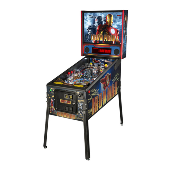
IRON MAN
IRON MAN PRO VAULT EDITION #500-55B0-01
1-800-KICKERS - parts.service@sternpinball.com
www.sternpinball.com - facebook.com/sternpinball
MANUAL #780-50B0-00
Advertisement
Table of Contents

Related Manuals for Stern Pinball IRON MAN


Summary of Contents for Stern Pinball IRON MAN
- Page 1 Stern Pinball machines are assembled in Elk Grove Village, Illinois, USA. Stern Pinball has inspected each game element to ensure it meets our quality standards. Each pinball machine has unique characteristics that make it a one-of-a-kind American made product. Each will have variations in appearance resulting from differences in the machine’s particular wood parts, individual printed art and mechanical assemblies.
-
Page 2: Table Of Contents
Warranty ............. 87 Playfield Bottom - Main Assem. and Switches .. 37 Warnings, Compliance, and Legal Notices ..87 Playfield - Rubber Parts ........38 Rubber Size Chart ..........38 IRON MAN PRO VAULT EDITION MANUAL 500-55B0-01 TM & © MARVEL... -
Page 3: Setup And Moving
Have someone help you carefully each side of the rear cabinet, 4 14. Install rear legs using the 4 bolts set the game down on the front total. removed from step 11. legs. IRON MAN PRO VAULT EDITION MANUAL 500-55B0-01 TM & © MARVEL... - Page 4 AND CORNER NICKS, WHICH CAN CAUSE THE GLASS TO FAIL CATASTROPHI- CALLY. TAKE CARE TO STORE THE GLASS ON A SOFT, ROOM-TEMPERATURE SURFACE AND PREVENT THE CORNERS FROM BEING DAMAGED. IRON MAN PRO VAULT EDITION MANUAL 500-55B0-01 TM & © MARVEL...
- Page 5 Play game: Check for satisfactory operation and adjust game volume (push the Red Buttons inside the Coin Door). If desired, perform any game diagnostics, game adjust- ments, and pricing settings at this time. IRON MAN PRO VAULT EDITION MANUAL 500-55B0-01 TM & © MARVEL...
-
Page 6: Adjustments Menu
HIGH SCORE #3 AWARDS COIN INPUT DELAY HIGH SCORE #4 AWARDS LOST BALL RECOVERY GRAND CHAMPION SCORE 75,000,000 COIN DOOR DISABLE TILT HIGH SCORE #1 55,000,000 HIGH SCORE #2 40,000,000 IRON MAN PRO VAULT EDITION MANUAL 500-55B0-01 TM & © MARVEL... - Page 7 Feature adjustments are changed similarly to standard adjustments using the SELECT button to choose options and the [<] [>] buttons to cycle through avail- able settings. IRON MAN PRO VAULT EDITION MANUAL 500-55B0-01 TM & © MARVEL...
-
Page 8: Transporting The Game
Stand the game up on its back. Remove the front two legs. 10. Secure all loose parts and trans- port with a hand truck in the upright position. IRON MAN PRO VAULT EDITION MANUAL 500-55B0-01 TM & © MARVEL... -
Page 9: Maintenance
• Ensure game volume is set appropriately for the location. Spare Fuses • Clean both sides of the playfield glass and reinstall. Iron Man Pro Vault Edition Deluxe Maintenance Kit 502-6003-B0 • Check and clean pinballs and replace if excessively worn or All standard kit items, plus: scuffed. -
Page 10: Updating Game Code For The S.a.m. System
4D: If more than one file is present on the memory stick, press [<] or [>] to locate your file. Press [SELECT] to update. 4E: Follow on-screen prompts. CPU/SOUND BOARD (S.A.M. SYSTEM) IRON MAN PRO VAULT EDITION MANUAL 500-55B0-01 TM & © MARVEL... -
Page 11: Fuses And Cabinet Switches
SETUP AND MOVING FOR PROPER OPERATION OF THIS PINBALL GAME, <4> PINBALLS MUST BE INSTALLED IN THE 4-BALL TROUGH! 1.8 FUSES AND CABINET SWITCHES IRON MAN PRO VAULT EDITION MANUAL 500-55B0-01 TM & © MARVEL... -
Page 12: Service Switch & Cpu Dip Switch Settings
Press [Back] to get back a menu, exit, or escape at any time. Back (or Exit). < Left , Right > Select (or Press to - Decrease ‘OK’). or + Increase values or to change settings. IRON MAN PRO VAULT EDITION MANUAL 500-55B0-01 TM & © MARVEL... -
Page 13: Diagnostic Aids
(press the black button again), select the “DIAG” icon and “TECH” icon or the technical alerts information. 1.11 CPU DIP SWITCH SETTINGS IRON MAN PRO VAULT EDITION MANUAL 500-55B0-01 TM & © MARVEL... - Page 14 SETUP AND MOVING USA & INTERNATIONAL (NON-EURO) STANDARD PRICING SELECT TABLE IRON MAN PRO VAULT EDITION MANUAL 500-55B0-01 TM & © MARVEL...
- Page 15 Default Highlighted NETHERLANDS 755-5401-03- Euro 3 Pos. Default Highlighted 755-5401-01- PORTUGAL Pos. Default Highlighted SPAIN 755-5401-08- Euro 8 = Factory Default = Not Shown on Coin Card HIGHLIGHTED HIGHLIGHTED IRON MAN PRO VAULT EDITION MANUAL 500-55B0-01 TM & © MARVEL...
- Page 16 SETUP AND MOVING IRON MAN PRO VAULT EDITION MANUAL 500-55B0-01 TM & © MARVEL...
-
Page 17: Switch Locations
SETUP AND MOVING 1.12 SWITCH LOCATIONS Switch Menu: Switch, Active, Single, & Service IRON MAN PRO VAULT EDITION MANUAL 500-55B0-01 TM & © MARVEL... - Page 18 SETUP AND MOVING IRON MAN PRO VAULT EDITION MANUAL 500-55B0-01 TM & © MARVEL...
-
Page 19: Lamp Locations
SETUP AND MOVING 1.13 LAMP LOCATIONS Lamp Menu: One, All, Row, Column, & Ordered IRON MAN PRO VAULT EDITION MANUAL 500-55B0-01 TM & © MARVEL... - Page 20 113-5034-08 Note: In Test Flash Lamps Menu ("Flash" Icon), only Flashers are tested in numeric order. Drive Driver Power Line Power Line Power Drive Transistor D.T. Control Coil GA-Turn IRON MAN PRO VAULT EDITION MANUAL 500-55B0-01 TM & © MARVEL...
-
Page 21: Coil Locations
SETUP AND MOVING 1.14 COIL LOCATIONS Coil Menu: Single Coild & Cycling Coil IRON MAN PRO VAULT EDITION MANUAL 500-55B0-01 TM & © MARVEL... -
Page 22: Service Menu System
(Installs, Custom MSG. Custom Pricing, Set Time, Reset, & USB) | TOUR: Go to tournament menu (Start Tournament, View Tournament Data, Sign Messages) Use both the manual and the display to help customize, troubleshoot, and/or diagnose faults, if any. IRON MAN PRO VAULT EDITION MANUAL 500-55B0-01 TM & © MARVEL... -
Page 23: Service Menu Icon Tree
SERVICE MENU SYSTEM 2.2 SERVICE MENU ICON TREE CONTINUATION OF CONTINUATION OF SUB-MENUS. SUB-MENUS. IRON MAN PRO VAULT EDITION MANUAL 500-55B0-01 TM & © MARVEL... - Page 24 SERVICE MENU SYSTEM SERVICE MENU ICON TREE CONTINUED Spider-Man™ Pinball Service Menu Icon Tree Continued CONTINUATION OF CONTINUATION OF SUB-MENUS. SUB-MENUS. IRON MAN PRO VAULT EDITION MANUAL 500-55B0-01 TM & © MARVEL...
-
Page 25: Problem/Solution Table
• If you cannot clear the situation by exiting back one menu, exit completely out of the service menu and re- lock up or the help display appears to be enter. If the problem persists, call technical support for additional help. non-functional IRON MAN PRO VAULT EDITION MANUAL 500-55B0-01 TM & © MARVEL... -
Page 26: Diagnostics Menu
Select the “CLR” icon to enter the ball trough test menu. Press the black [SELECT] buttons. To return to the diagnostics menu, press the green [BACK] button. This feature is also useful to retrieve a pinball for game testing in switch or coil tests. IRON MAN PRO VAULT EDITION MANUAL 500-55B0-01 TM & © MARVEL... - Page 27 Note: A factory reset will also put the switch back “IN SERVICE” in which the game will need to redetermine if the switch should be marked “OUT OF SERVICE”. IRON MAN PRO VAULT EDITION MANUAL 500-55B0-01 TM & © MARVEL...
- Page 28 The test pulses each flash lamp sequentially (cycling) on the playfield and in the backbox (if flash lamps are used). The dot matrix display indicates the same information you will find in Single Flash Lamp Test. IRON MAN PRO VAULT EDITION MANUAL 500-55B0-01 TM & © MARVEL...
- Page 29 Identical to Single Lamp Test, however, the lamps lit are not in the lamp matrix numeric order, but ordered and arranged in seperate localized grouping(s) for easier lamp checking. IRON MAN PRO VAULT EDITION MANUAL 500-55B0-01 TM & © MARVEL...
- Page 30 In this game four (4) pinballs are used and required for proper operation. CAUTION! Continuous use of the above test may overheat the trough up-kicker coil. IRON MAN PRO VAULT EDITION MANUAL 500-55B0-01 TM & © MARVEL...
- Page 31 Note on Device Malfunction: While in the technician alerts menu, if the following is displayed, the game has detected a “device malfunction”. Check the device indicated (coil and/or switch). IRON MAN PRO VAULT EDITION MANUAL 500-55B0-01 TM & © MARVEL...
- Page 32 Test, and Sound/Speaker Test. Press the green [BACK] button to pause and to view cumulative burn-in minutes. Press the green [BACK] button again to return to the diagnostic menu. IRON MAN PRO VAULT EDITION MANUAL 500-55B0-01 TM & © MARVEL...
- Page 33 & illuminating the next column, until each column has been individually lit, while the other columns are off. Illuminates all the dots alternating even & odd in both the rows and columns IRON MAN PRO VAULT EDITION MANUAL 500-55B0-01 TM & © MARVEL...
-
Page 34: Parts Identification & Location
1/4" Cable Clamp 545-7877-00 Fische Paper 036-5260-33 14 Pin Ribbon (Not Shown) 036-5452-02 2 Spkr in Series (Not Shown) 036-5520-00 LED Display 5v (Not Shown) ATTACH SPEAKER FILTER TO THIS STUD IRON MAN PRO VAULT EDITION MANUAL 500-55B0-01 TM & © MARVEL... -
Page 35: Cabinet Parts
GRILL - SPEAKER / VENT 660-5001-00 PLAYFIELD GLASS 031-5007-01 SPEAKER, CABINET 8" ROUND, 4 OHM 820-66B0-XX Cabinet Decal Replacement Set, Speaker 545-5090-00 CASH BOX - PLASTIC Panel Decal Not Included IRON MAN PRO VAULT EDITION MANUAL 500-55B0-01 TM & © MARVEL... -
Page 36: Playfield Top - Main Assem. & Switches
535-8145-00 Shooter Lane Ramp 550-5031-06 Dome (Yellow) 550-5031-02 Dome (Red) 550-5032-07 Dome Hat (Orange) 550-5032-06 Dome Hat (Yellow) 550-5032-02 Dome Hat (Red) Figure 3.4.1. Major playfield assemblies, Top locations. IRON MAN PRO VAULT EDITION MANUAL 500-55B0-01 TM & © MARVEL... -
Page 37: Playfield Bottom - Main Assem. And Switches
Diode Terminal Strip 5-Lug 535-5988-01 Bracket, Edge Slide 500-5329-03 Bracket, Pivot Pin Welded Assembly 535-8964-00 Bracket, Back Panel Mounting 545-5253-01 Tie Post 3-1/2" Figure 3.5.1. Major playfield assemblies, Bottom locations. IRON MAN PRO VAULT EDITION MANUAL 500-55B0-01 TM & © MARVEL... -
Page 38: Playfield - Rubber Parts
Figure 3.7.1. Rubber ring inner diameter sizing tool. Hold ring up to chart and read largest size on inside of ring. Dimensions are In- ner Diameter (ID) unless otherwise noted as Outer Diamter (OD). IRON MAN PRO VAULT EDITION MANUAL 500-55B0-01 TM & © MARVEL... -
Page 39: Major Assemblies
SCREW, 2-56 X 1/2" HWH MS 535-6539-00 SWITCH BODY PROTECT PLATE 180-5157-01 SHOOTER SWITCH - SHORT ARM 545-6268-00 FISCHE PAPER 535-0762-00 COIL BRACKET-AUTOPLUNGER 515-6304-03 PLUNGER / LINK ASSEMBLY 545-0762-00 FISCHE PAPER: AUTO-LAUNCHER IRON MAN PRO VAULT EDITION MANUAL 500-55B0-01 TM & © MARVEL... -
Page 40: Flipper Assembly, Left
FLIPPER REBUILD KIT, RIGHT * Refer to game rubber chart for flipper rubber * Refer to game rubber chart for flipper rubber color and part number. color and part number. IRON MAN PRO VAULT EDITION MANUAL 500-55B0-01 TM & © MARVEL... -
Page 41: Slingshot Assembly
535-7801-00 TROUGH BALL GUIDE PLATE 515-0173-00 DUAL OPTO TRANS BOARD ASSEMBLY 515-0174-00 DUAL OPTO REC BOARD ASSEMBLY AP-A 535-7329-01 BALL TROUGH ENTER/EXIT SCOOP AP-B 260-5000-00 STEEL BALLS (1-1/16" ) IRON MAN PRO VAULT EDITION MANUAL 500-55B0-01 TM & © MARVEL... -
Page 42: Pop Bumper Assembly
COIL BRACKET POP BUMPER ASSY 545-5607-00 BUMPER SKIRT 18 545-5609-00 FIBER YOKE 266-5048-00 BUMPER SKIRT COMP SPRING 19 535-7346-00 METAL YOKE 545-5195-00 BUMPER BASE 20 237-5957-00 #6-32 x 1-3/16" SPIRAL FIN SHANK SCREW IRON MAN PRO VAULT EDITION MANUAL 500-55B0-01 TM & © MARVEL... -
Page 43: Left Ramp Assembly
MINI MARS W/ EARS - RED SB 820-6561-30 DECAL #30 - LEFT RAMP - I.M. 232-5202-02 SCREW, 6-32 X 1/2" PPH MS SEMS 820-6561-31 DECAL #31 - LEFT RAMP - I.M. IRON MAN PRO VAULT EDITION MANUAL 500-55B0-01 TM & © MARVEL... -
Page 44: Right Ramp Assembly
DECAL #33 - RIGHT RAMP - I.M. 550-5031-02 MINI MARS W/ EARS - RED SB 820-6561-34 DECAL #34 - RIGHT RAMP - I.M. 550-5031-06 MINI MARS W/ EARS - YELLOW SB IRON MAN PRO VAULT EDITION MANUAL 500-55B0-01 TM & © MARVEL... -
Page 45: Kicker Assembly
OPTO TRANSCEIVER ASSY, 15" LEADS 535-0351-02 BALL GUIDE #2 - KICKER - I.M. 237-5880-00 SCREW, #6 X 3/8 PPH T-25 515-0215-01 OPTO TRANSCEIVER ASSY, 15" LEADS 237-5880-00 SCREW, #6 X 3/8 PPH T-25 IRON MAN PRO VAULT EDITION MANUAL 500-55B0-01 TM & © MARVEL... -
Page 46: Monger Motor & Switch Assembly
Part Number Description 515-7730-00 WELDMENT, GUIDE SUPPORT, MONGER 530-6561-00 GUIDE ROD, IRON MONGER 511-6757-00 ASSEMBLY, IRON MONGER LIFT 270-5003-00 RETAINING RING 5/16" 237-5602-00 SCREW, 8-32 X 1/2 PPH MS, ZINC IRON MAN PRO VAULT EDITION MANUAL 500-55B0-01 TM & © MARVEL... -
Page 47: Iron Monger Lift Assembly
DECAL #35, IRON MONGER 820-6561-37 DECAL #37, IRON MONGER 820-6561-38 DECAL #38, IRON MONGER 820-6561-39 DECAL #39, IRON MONGER 820-6561-40 DECAL #40, IRON MONGER 040-5001-00 CABLE TIE, 4" 036-5547-10-B0 FLEXIBLE OPTO CABLE IRON MAN PRO VAULT EDITION MANUAL 500-55B0-01 TM & © MARVEL... -
Page 48: Schematics, Wiring & Pcbs
113-5034-08 Note: In Test Flash Lamps Menu ("Flash" Icon), only Flashers are tested in numeric order. Drive Driver Power Line Power Line Power Drive Transistor D.T. Control Coil GA-Turn IRON MAN PRO VAULT EDITION MANUAL 500-55B0-01 TM & © MARVEL... - Page 49 These Coil Fuses are located I/O PCB NEAR +50VDC under the play eld the assembly. Coil Diodes (1N4004) are integrated on the I/O Power Driver PC Board. RED-YEL VOLTAGE OUTPUTS IRON MAN PRO VAULT EDITION MANUAL 500-55B0-01 TM & © MARVEL...
- Page 50 ROW 6 GRN BLK ROW 5 GRN YEL ROW 4 GRN ORG ROW 3 GRN RED ROW 2 GRN BRN ROW 1 DISPLAY XILINX SERIAL PORT PORT JTAG PROCESSOR IRON MAN PRO VAULT EDITION MANUAL 500-55B0-01 TM & © MARVEL...
-
Page 51: Playfield Wiring
SCHEMATICS, WIRING & PCBS 5.2 PLAYFIELD WIRING GENERAL ILLUMINATION MAP IRON MAN PRO VAULT EDITION MANUAL 500-55B0-01 TM & © MARVEL... - Page 52 IC-U15B WHT-VIO IC-U15C WHT-GRY IC-U15D BLACK Ground TAN-BLK IC-U35A TAN-RED IC-U35B TAN-ORG IC-U35C TAN-YEL IC-U35D [ 5 KEY ] TAN-GRN IC-U40A TAN-BLU IC-U40B TAN-VIO IC-U40C TAN-WHT IC-U40D SWITCH RETURNS IRON MAN PRO VAULT EDITION MANUAL 500-55B0-01 TM & © MARVEL...
- Page 53 YEL-RED YEL-BRN Return 1 Return 2 Return 3 Return 4 Return 5 Return 6 Return 7 Return 8 Return 9 Return 10 Return Transistor STP20N10L Lamp Source Number : IRON MAN PRO VAULT EDITION MANUAL 500-55B0-01 TM & © MARVEL...
- Page 54 Section , Chapter , Play eld Wiring. Note: Coil Diodes (1N4004) are integrated on the I/O Power Driver PC Board. RED-YEL 50VDC RED-YEL 50VDC IRON MAN PRO VAULT EDITION MANUAL 500-55B0-01 TM & © MARVEL...
-
Page 55: Cabinet And Coin Door Wiring
SPI Nr.: 010-5015-00 100VAC / 105VAC SPI Nr.: 165-5011-01 BLK-WHT 100/105 VOLTS VOLTS FLUORESCENT TUBE 24" (F20T9CW) SPI Nr.: 165-5061-00 FLUORESCENT TUBE, STARTER & BALLAST LOCATED IN THE BACKBOX IRON MAN PRO VAULT EDITION MANUAL 500-55B0-01 TM & © MARVEL... - Page 56 GRN-BRN YEL-RED DIODE IN CONNECTOR YEL-BRN TAN-VIO 2-LUG DIODE TERMINAL STRIP N.O. TAN-WHT ORG-BRN RED-BRN SW. 16 LAMP 1 START BUTTON START BUTTON CPU/Sound PCB I/O POWER DRIVER PCB IRON MAN PRO VAULT EDITION MANUAL 500-55B0-01 TM & © MARVEL...
- Page 57 PNK-GRN (P-5) SW. D-5 CPU J2-P7 5TH COIN SLOT BLOCK CONNECTOR PNK-YEL (P-6) SW. D-4 CPU J2-P6 4TH COIN SLOT ~ WIRING CONFIGURATION WILL VARY ACCORDING TO COUNTRY ~ IRON MAN PRO VAULT EDITION MANUAL 500-55B0-01 TM & © MARVEL...
-
Page 58: Printed Circuit Boards
" 6 (26-60-5030) 2N3906 Replacement Part: 2N3906 LED TLRH180P Replacement Part: (T1-3/4 GaAIAs) LED TLRH180P SPI Part N : 1 (T1-3/4 GaAIAs) 165-5052-00 SPI Part N : 1 165-5052-00 IRON MAN PRO VAULT EDITION MANUAL 500-55B0-01 TM & © MARVEL... - Page 59 Trough Plunger with a fingertip should block the BEAM and cause the Switch Position to trigger (see Fig. 2). View Fig. 2a & 2b (on the next page) for a sectional view of the Light Path (note alignment) and what happens as a ball breaks the light beam. IRON MAN PRO VAULT EDITION MANUAL 500-55B0-01 TM & © MARVEL...
- Page 60 “double stacked” ball scenario breaks the light beam. IMPORTANT If replacement of LED is required, insure that it is mounted correctly before and after soldering (See Fig. 4a/4b). IRON MAN PRO VAULT EDITION MANUAL 500-55B0-01 TM & © MARVEL...
- Page 61 SCHEMATICS, WIRING & PCBS I/O POWER DRIVER PCB S.A.M. SYSTEM SCHEMATIC (SHEET 1 OF 4) IRON MAN PRO VAULT EDITION MANUAL 500-55B0-01 TM & © MARVEL...
- Page 62 SCHEMATICS, WIRING & PCBS I/O POWER DRIVER PCB S.A.M. SYSTEM SCHEMATIC (SHEET 1 OF 4) IRON MAN PRO VAULT EDITION MANUAL 500-55B0-01 TM & © MARVEL...
- Page 63 SCHEMATICS, WIRING & PCBS I/O POWER DRIVER PCB S.A.M. SYSTEM SCHEMATIC (SHEET 2 OF 4) IRON MAN PRO VAULT EDITION MANUAL 500-55B0-01 TM & © MARVEL...
- Page 64 SCHEMATICS, WIRING & PCBS I/O POWER DRIVER PCB S.A.M. SYSTEM SCHEMATIC (SHEET 2 OF 4) IRON MAN PRO VAULT EDITION MANUAL 500-55B0-01 TM & © MARVEL...
- Page 65 SCHEMATICS, WIRING & PCBS I/O POWER DRIVER PCB S.A.M. SYSTEM SCHEMATIC (SHEET 3 OF 4) IRON MAN PRO VAULT EDITION MANUAL 500-55B0-01 TM & © MARVEL...
- Page 66 SCHEMATICS, WIRING & PCBS I/O POWER DRIVER PCB S.A.M. SYSTEM SCHEMATIC (SHEET 3 OF 4) IRON MAN PRO VAULT EDITION MANUAL 500-55B0-01 TM & © MARVEL...
- Page 67 SCHEMATICS, WIRING & PCBS I/O POWER DRIVER PCB S.A.M. SYSTEM SCHEMATIC (SHEET 4 OF 4) IRON MAN PRO VAULT EDITION MANUAL 500-55B0-01 TM & © MARVEL...
- Page 68 SCHEMATICS, WIRING & PCBS I/O POWER DRIVER PCB S.A.M. SYSTEM SCHEMATIC (SHEET 4 OF 4) IRON MAN PRO VAULT EDITION MANUAL 500-55B0-01 TM & © MARVEL...
- Page 69 SCHEMATICS, WIRING & PCBS I/O POWER DRIVER PCB S.A.M. SYSTEM COMPONENT LAYOUT IRON MAN PRO VAULT EDITION MANUAL 500-55B0-01 TM & © MARVEL...
- Page 70 Transistor Tht. TO-220 TIP122 NPN 100V 5A Q27, Q28, Q29, Q30, Q31, Q32 100-6003-00 (221-0000972) U18, U22, U24 I.C. SM SOIC 74HC245 Oct. Bus. Xcvr. 100-6000-00 (221-0011253) I.C. SM SOIC DS1832S. SO-8 IRON MAN PRO VAULT EDITION MANUAL 500-55B0-01 TM & © MARVEL...
- Page 71 BRDG 4 & 5 (Mfg. .169" I.D. X 9/32" O.D. X 1/4") 1/4" Slf. Rtn. Spacer White 254-5007-05 (507-0004547) for BRDG 1, 2, & 3 and for Mounting Holes 5/16" Slf. Rtn. Spacer White IRON MAN PRO VAULT EDITION MANUAL 500-55B0-01 TM & © MARVEL...
- Page 72 X2_D9 I/O6 I/O9 I/O6 I/O9 I/O7 I/O8 I/O7 I/O8 NW E X2_NWE RAMW X2_A16 X2_A9 MMBF170 X2_A15 X2_A10 BRAM NR D/NOE X2_A14 X2_A11 128K X 8 RAM DT71V416YS IDT71V016SA IRON MAN PRO VAULT EDITION MANUAL 500-55B0-01 TM & © MARVEL...
- Page 73 RESET# RESET# RESET# DQ11 DQ11 VPEN XTCK WP#/ACC WP#/ACC P10/IRQ1 P10/IRQ1 XTDO RY/BY# DQ10 RY/BY# DQ10 XTDI XTMS STERN PINBALL, INC. CPU / Sound PCB (S.A.M. System) S29GL128N S29GL128N IRON MAN PRO VAULT EDITION MANUAL 500-55B0-01 TM & © MARVEL...
- Page 74 +3.3V U40B U40C U40D SW DIP8 +3.3V +3.3V 74LVC245 R183 74LVC245 +3.3V R184 DPSW R185 SWM [2] R186 C185 R187 0.1 UF R188 R189 R190 +3.3V 1X10 74LVC245 DPSW IRON MAN PRO VAULT EDITION MANUAL 500-55B0-01 TM & © MARVEL...
- Page 75 U40A SMT4148 +4.5V 1X10 LM339 R173 SWITCH SMT4148 ROWS U40B R174 SMT4148 LM339 +4.5V U40C VREF STERN PINBALL, INC. +4.5V LM339 CPU / Sound PCB (S.A.M. System) U40D LM339 IRON MAN PRO VAULT EDITION MANUAL 500-55B0-01 TM & © MARVEL...
- Page 76 0.1 UF 0.1 UF 0.1 UF 0.1 UF 15UH C241 C178 0.1 UF 4.7UF HOST BRESET# TYPE A DATA– R129 USB_DM DATA+ R130 USB_DP RPD_EN R11 7 R11 8 IRON MAN PRO VAULT EDITION MANUAL 500-55B0-01 TM & © MARVEL...
- Page 77 PUMP_EN SESS_LOW +3.3V AT43USB380 +3.3V 100K USB_DM USB_DP RPD_EN TP12 6.000MHz C100 STERN PINBALL, INC. 22PF 22PF .033UF .033 UF 470PF 2. 2UF CPU / Sound PCB (S.A.M. System) IRON MAN PRO VAULT EDITION MANUAL 500-55B0-01 TM & © MARVEL...
- Page 78 Mounting Hole 0.235 with Vias 0.235 with Vias FIDUCIALS TOOLING HOLES FID1 FID2 FID3 FID4 FID5 FID6 FID7 ZG1 0 Mounting Hole Mounting Hole Mount ing Hole 0.235 with Vias IRON MAN PRO VAULT EDITION MANUAL 500-55B0-01 TM & © MARVEL...
- Page 79 T1OUT PHONE RS232_R D0 JACK R1IN RS232_TD1 T2OUT RS232_R D1 R2IN TXD0 T1IN RXD0 R1OUT STERN PINBALL, INC. TXD1 T2IN CPU / Sound PCB (S.A.M. System) RXD1 R2OUT SP232ACT IRON MAN PRO VAULT EDITION MANUAL 500-55B0-01 TM & © MARVEL...
- Page 80 TP17 OUTA 0.01 UF R144 -INA OUTB +INA -INB C159 1500PF +INB R141 OPA2353 C108 C109 470PF 470PF R137 +12V +5 AUD FB-0805 LM340T-5.0 C170 C169 0.1 UF 10UF IRON MAN PRO VAULT EDITION MANUAL 500-55B0-01 TM & © MARVEL...
- Page 81 0.1 UF R206 22UF DL4004 DL4004 680PF -12V C237 C238 C239 C240 100 UF 0.1 UF 0.1 UF 0.1 UF STERN PINBALL, INC. CPU / Sound PCB (S.A.M. System) IRON MAN PRO VAULT EDITION MANUAL 500-55B0-01 TM & © MARVEL...
- Page 82 SCHEMATICS, WIRING & PCBS CPU/SOUND PCB S.A.M. SYSTEM COMPONENT LAYOUT IRON MAN PRO VAULT EDITION MANUAL 500-55B0-01 TM & © MARVEL...
- Page 83 L4, L5, L6, L7, L8, L9 Ind.-SM Ferrite 100Ω 1234 Smt. 125-6012-00 (161-0007286) L1, L2 Ind.-SM Ferrite 805 Bead 600Ω 100Mhz 25% 500mA 125-6021-00 (161-0009686) Ind.-SM EP Inductor15uH 1100mA 20% IRON MAN PRO VAULT EDITION MANUAL 500-55B0-01 TM & © MARVEL...
- Page 84 240-5318-00 (503-0004457) for Heatsinks U33, U34, U50, U51 #4-40 Keps Nut 254-5007-05 (507-0004547) for Mntg. Holes (Mfg. .169" I.D. X 9/32" O.D. X 5/16") 5/16" Slf. Rtn. Spacer White IRON MAN PRO VAULT EDITION MANUAL 500-55B0-01 TM & © MARVEL...
- Page 85 SCHEMATICS, WIRING & PCBS PLAYFIELD OPTO INTERFACE BOARD WIRING CONFIGURATION 01/17/20 Opto Interface Board REYNA IRONMAN IRON MAN PRO VAULT EDITION MANUAL 500-55B0-01 TM & © MARVEL...
-
Page 86: Specifications
Nominal Line Power Current rating for your line voltage. For example, a 15A 120V household circuit, 15/3 A (nominal current) = 5 games maximum. IRON MAN PRO VAULT EDITION MANUAL 500-55B0-01 TM & © MARVEL... -
Page 87: Warranty
STERN PINBALL INC LIMITED WARRANTY disorientation, confusion, momentary loss of awareness, and loss of Stern Pinball Inc (‘SELLER’) warrants only to the initial purchaser of its consciousness or convulsions that can lead to injury from falling down or striking nearby objects. - Page 88 1-800-KICKERS IRON MAN PRO VAULT EDITION #500-55B0-01 MANUAL #780-50B0-00 PARTS.SERVICE@STERNPINBALL.COM WWW.STERNPINBALL.COM *780-50B0-00* FACEBOOK.COM/STERNPINBALL...
Need help?
Do you have a question about the IRON MAN and is the answer not in the manual?
Questions and answers