Table of Contents
Advertisement
Advertisement
Table of Contents

Related Manuals for Phonic MM1705a


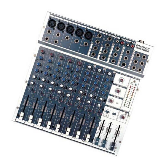
Summary of Contents for Phonic MM1705a
- Page 2 Your Phonic MM1705 was carefully packed in the factory and the packing box was designed to protect the unit from rough handling. We recommend that you carefully examine the packaging and its contents for any signs of physical damage, which may have occurred in transportation.
-
Page 3: Table Of Contents
EFX RTN............12 SYSTEM BLOCK DIAGRAM....21 2T RTN............12 APPENDIX:.........22 1: SUGGESTED READING....22 2: GLOSSARY........23 Phonic reserves the right to improve or alter any information supplied within this document without prior notice. V1.1 Nov. 19, 2002 PHONIC CORPORATION MM1705a USER’S MANUAL Page 3... -
Page 4: Introduction
60mm high quality linear faders connections. Dual 13-segments LED level meter 2 audio groups Always turn on the MM1705a mixer before the Stereo main output power amplifier; turn off the MM1705a mixer after Mono main output turning off the amplifier. -
Page 5: Converting To Rackmount Mode
1-6. on a standard 19” rack. It is simple to install the rack 2. Install the mixer on the rack. mount kit by the following procedure: PHONIC CORPORATION MM1705a USER’ S MANUAL Page 5... -
Page 6: Connecting It Up
CONNECTING IT UP CONNECTING IT UP MM1705a USER’ S MANUAL PHONIC CORPORATION Page 6... -
Page 7: Typical Connecting Leads
TYPICAL CONNECTING LEADS TYPICAL CONNECTING LEADS PHONIC CORPORATION MM1705a USER’ S MANUAL Page 7... -
Page 8: Unbalanced & Balanced
2 connected units are not identical. This means the system is much easierto experience noise interference.Running long cables is easy for a balanced system but difficult for an MM1705a USER’ S MANUAL PHONIC CORPORATION Page 8... -
Page 9: Channel Strip Description
Always begin with all con- a high frequency cut of 15dB in the trols in the “0” position and avoid ex- equalizer. Only channel 1&2 feature cessively cutting/boosting large seg- with inserts. PHONIC CORPORATION MM1705a USER’ S MANUAL Page 9... -
Page 10: Aux / Efx Section
These are used to set up separate to add-on a compressor, limiter or mixes for a foldback system and exter- gate. Please refer to Phonic nal processing machines and PCL3200 or MCL2000 for further in- recording.The AUX send can be set as formation. -
Page 11: L/R Or Gp (Routing Switch)
Group 1 and extremely right only feed Groups 2. 7 CHANNEL FADER A long-throw 60mm linear fader de- termines the proportion of the chan- nel in the mix and provides a clear visual indication of channel level. PHONIC CORPORATION MM1705a USER’ S MANUAL Page 11... -
Page 12: Stereo Channels 6-11
This knob controls the level sent to the mas- ter L/R. When you would like to monitor the signal from the 2T RTN, simply depress the PFL button, the input signal will be fed into CTRL RM. MM1705a USER’ S MANUAL PHONIC CORPORATION Page 12... -
Page 13: Master Section Description
GROUP 1/2 faders. 15 GROUP 1/2 FADER A long-throw 60mm linear fader determines the proportion of the group signal in the mix and provides a clear visual indication of chan- nel level. PHONIC CORPORATION MM1705a USER’ S MANUAL Page 13... -
Page 14: Master Display
+48V master switch is on. MM1705a USER’ S MANUAL PHONIC CORPORATION Page 14... -
Page 15: Initial Set Up
Set EQ control to the center position. Set PAN and BALANCE knobs to the center position. You need headphones to continue. Apply a typical performance level signal, monitoring the level on the LED meter. PHONIC CORPORATION MM1705a USER’ S MANUAL Page 15... -
Page 16: Applications
APPLICATIONS APPLICATION1: LIVE SOUND REINFORCEMENT MM1705a USER’ S MANUAL PHONIC CORPORATION Page 16... -
Page 17: 2:Sub Mixing
APPLICATIONS APPLICATION2: SUB MIXING PHONIC CORPORATION MM1705a USER’ S MANUAL Page 17... -
Page 18: 3:Music Club
APPLICATIONS APPLICATION3: MUSIC CLUB MM1705a USER’ S MANUAL PHONIC CORPORATION Page 18... -
Page 19: Dimensions
DIMENSIONS Measurements are shown in mm/inch. PHONIC CORPORATION MM1705a USER’ S MANUAL Page 19... -
Page 20: Specfications
SPECIFICATIONS Due to continually improving product performance, specifications are subject to change without notice. MM1705a USER’ S MANUAL PHONIC CORPORATION Page 20... -
Page 21: System Block Diagram
SYSTEM BLOCK DIAGRAM PHONIC CORPORATION MM1705a USER’ S MANUAL Page 21... -
Page 22: Appendix
APPENDIX APPENDIX 1: SUGGESTED READING APPENDIX 2: GLOSSARY Phonic recommends the following books for those AFL (After-Fader-Listening) interested in advanced audio engineering and sound Acronym for after fader listen, also known as post- system operation: fader solo function. Sound System Engineering by Don and Carolyn... -
Page 23: 2: Glossary
Signals that reinforce each other are In- the phantom power supply for channel mic inputs, for phase; signals that cancel each other are out-of condenser microphones and active DI boxes. phase. PHONIC CORPORATION MM1705a USER’ S MANUAL Page 23...
Need help?
Do you have a question about the MM1705a and is the answer not in the manual?
Questions and answers