Advertisement
Instruction Manual
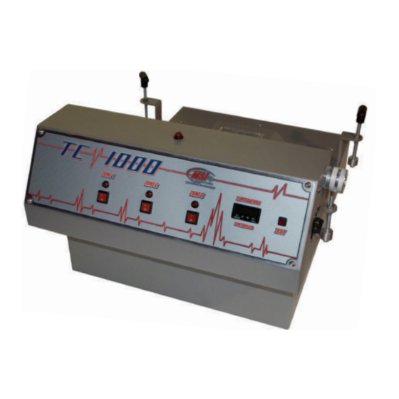
Quartz Flash Cure Units
TC 1000 and VersiFlash TC
TC 1000 Features:
Machine Interface • Temperature Control
Three Individual Zones
VersiFlash TC Features:
Machine Interface • Temperature Control • Intensity Control
Three Individual Zones • Stand By Mode with Intensity Control
Dwell Timer (for use with External Sensor)
Advertisement
Table of Contents

Related Manuals for MSI TC 1000


Summary of Contents for MSI TC 1000
- Page 1 Instruction Manual Quartz Flash Cure Units TC 1000 and VersiFlash TC TC 1000 Features: Machine Interface • Temperature Control Three Individual Zones VersiFlash TC Features: Machine Interface • Temperature Control • Intensity Control Three Individual Zones • Stand By Mode with Intensity Control...
-
Page 2: Table Of Contents
Index Safety ......................Pg. 2 Bulb Installation ....................Pg. 3, 4 Initial Setup ....................Pg. 5 Operational Controls ..................Pg. 6 Operating Instructions ..................Pg. 7, 8 Components Reference..................Pg. 9, 10 Parts List ......................Pg. 11... -
Page 3: Safety
WARNING For Your Own Safety, Read Instructions Before Operating This Equipment The Versiflash TC is designed to quickly emit very high infra-red heat and can cause fire if not used properly. Always Test the unit prior to production to ensure that Temperature Control and power settings are correct. -
Page 4: Bulb Installation
BULB INSTALLATION FAN WIRE PLUG BULBS NEED TO BE INSTALLED BRASS BEFORE USE: To avoid damage during THUMB shipping units are shipped without bulbs NUTS installed. The bulbs are carefully packed and are located inside the unit under the fan cover. To access the bulbs ( See Fig. - Page 5 WIRING BULBS CONTINUED: Zone 1 Block With the Flash Unit in front of you ( back of FIG. 3 control box facing you ) See fig. 3 Start attaching bulb wires to ceramic blocks in groups of 3 (9 bulb units) or 4 (12 bulb units) Insulation on the bulb wires is striped back about ½...
-
Page 6: Initial Setup
Failure to follow this specific direction will void every and all warrenties immediately. MSI will assume no responsibility for any injury or damage if wiring of the electrical service to this machine is not done by a trained professional. -
Page 7: Operational Controls
Operational Controls Read Carefully DWELL TIMER (for external sensor only) When using flash with an external sensor, the Dwell Timer should be set to “D” . The time setting will determine the length of the flash–cure cycle. When using the Test button, the Dwell Timer will determine the test cycle time. -
Page 8: Operating Instructions
Operating Instructions The Versi Flash TC and the TC 1000 are equipped with a temperature sensor and controller that will prevent under curing and over curing of the garments. This feature will also prevent damage to honeycomb pallets that may have come with your machine. - Page 9 #2: RUNNING THE FLASH CURE IN INTERNAL MODE With the MHM main computer set for Flash Internal Mode, program the desired flash time. When the first platen programmed to flash moves under the flash cure unit it will flash for the Time programmed and another cycle will begin.
-
Page 10: Components Reference
POWER INDICATOR LED (TOP CONTROL BOX) VF16-A TEST BUTTON VF17-O INTERFACE CABLE ORIGINAL VERSI FLASH VF17-TC VERSI FLASH TC / TC 1000 INTERFACE CABLE VF17-XTC INTERFACE CABLE X - TYPE ONLY VF18-A 50 AMP ON/OFF BREAKER 3 PHASE VF18-B 70 AMP ON/OFF BREAKER SINGLE PHASE VF19-A 19"...
Need help?
Do you have a question about the TC 1000 and is the answer not in the manual?
Questions and answers