Table of Contents
Advertisement
Quick Links
Advertisement
Chapters
Table of Contents

Related Manuals for Clevo M660SE


Summary of Contents for Clevo M660SE
- Page 1 https://appliancetechmanuals.com...
- Page 2 https://appliancetechmanuals.com...
- Page 3 Preface Notebook Computer M660SE/ M665SE Service Manual...
- Page 4 https://appliancetechmanuals.com Preface Notice The company reserves the right to revise this publication or to change its contents without notice. Information contained herein is for reference only and does not constitute a commitment on the part of the manufacturer or any subsequent ven- dor.
- Page 5 This manual is intended for service personnel who have completed sufficient training to undertake the maintenance and inspection of personal computers. It is organized to allow you to look up basic information for servicing and/or upgrading components of the M660SE/ M665SE series notebook PC.
- Page 6 https://appliancetechmanuals.com Preface IMPORTANT SAFETY INSTRUCTIONS Follow basic safety precautions, including those listed below, to reduce the risk of fire, electric shock and injury to per- sons when using any electrical equipment: 1. Do not use this product near water, for example near a bath tub, wash bowl, kitchen sink or laundry tub, in a wet basement or near a swimming pool.
- Page 7 https://appliancetechmanuals.com Preface Instructions for Care and Operation The notebook computer is quite rugged, but it can be damaged. To prevent this, follow these suggestions: Don’t drop it, or expose it to shock. If the computer falls, the case and the components could be damaged. Do not expose the computer Do not place it on an unstable Do not place anything heavy...
- Page 8 https://appliancetechmanuals.com Preface Avoid interference. Keep the computer away from high capacity transformers, electric motors, and other strong mag- netic fields. These can hinder proper performance and damage your data. Take care when using peripheral devices. Use only approved brands of Unplug the power cord before peripherals.
- Page 9 https://appliancetechmanuals.com Preface Battery Precautions • Only use batteries designed for this computer. The wrong battery type may explode, leak or damage the computer. • Do not continue to use a battery that has been dropped, or that appears damaged (e.g. bent or twisted) in any way. Even if the computer continues to work with a damaged battery in place, it may cause circuit damage, which may possibly result in fire.
- Page 10 https://appliancetechmanuals.com Preface Related Documents You may also need to consult the following manual for additional information: User’s Manual on CD This describes the notebook PC’s features and the procedures for operating the computer and its ROM-based setup pro- gram. It also describes the installation and operation of the utility programs provided with the notebook PC. VIII...
-
Page 11: Table Of Contents
External Locator - Left & Right Side Views ........1-8 External Locator - Bottom View .............1-9 SYSTEM BLOCK DIAGRAM ............B-2 M660SE Mainboard Overview - Top (Key Parts) ......1-10 CLOCK GENERATOR ..............B-3 M660SE Mainboard Overview - Bottom (Key Parts) ....1-11 CPU-1 .....................B-4 M660SE Mainboard Overview - Top (Connectors) ......1-12... - Page 12 https://appliancetechmanuals.com Preface CRT & LVDS ................B-25 CPU FAN, LPC ROM ..............B-26 MINI-PCI & BLUETOOTH ............B-27 AUDIO VT1708A/ALC883 ............B-28 LED ....................B-29 CHARGER, DC IN ..............B-30 1.05VS, 1.5V, 2.5VS ..............B-31 VCORE ..................B-32 1.8V, 0.9VS .................. B-33 VDD3, VDD5 ................
-
Page 13: Introduction
Chapter 1: Introduction Overview This manual covers the information you need to service or upgrade the M660SE/M665SE series notebook computer. Information about operating the computer (e.g. getting started, and the Setup utility) is in the User’s Manual. Information about drivers (e.g. VGA & audio) is also found in User’s Manual. That manual is shipped with the computer. -
Page 14: System Specifications
https://appliancetechmanuals.com Introduction System Specifications Latest Specification Information The specifications listed in this Appendix are correct at the time of going to press. Certain items (particularly processor types/speeds and CD/DVD device types) may be changed, delayed or updated due to the manufacturer's release schedule. Check with your service center for details. - Page 15 https://appliancetechmanuals.com Introduction Feature Specification Security Security (Kensington® Type) Lock Slot BIOS Password BIOS One 4Mb Flash ROM Phoenix™ BIOS 15.4" WXGA (1280 * 800) TFT LCD Video Adapter VIA VN896 Integrated Video System (Internal On Chip) Chrome 9HC™ Integrated 128bit 2D/3D Graphic Engine and Clock up to 250MHz Supports CRT Resolutions up to 2048 * 1536 at 75Hz Supports Microsoft DirectX 9.0 Storage...
- Page 16 https://appliancetechmanuals.com Introduction Feature Specification Power Supports ACPI 2.0 and PCI Bus Power Management 1.1 Battery Low Suspend Management Compliant Supports Wake on LAN Power Full Range AC/DC Adapter 19V, 3.42A or 18.5V, 3.5A (65W), 100~240V, 50~60Hz Battery 6 Cell Smart Lithium-Ion Battery Pack, 4000mAH Environmental Temperature Relative Humidity...
-
Page 17: Model Differences
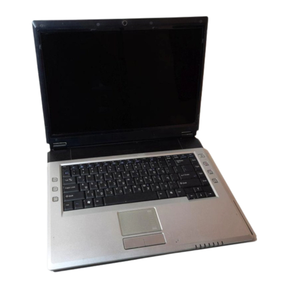
Introduction Model Differences The models vary slightly in external cover design and color. Figure 1 Model Differences M660SE M665SE System Specifications 1 - 5... -
Page 18: External Locator - Top View With Lcd Panel Open
https://appliancetechmanuals.com Introduction External Locator - Top View with LCD Panel Open Figure 2 Top View 1. Optional Built-In PC Camera 2. LCD 3. Speakers 4. Power Button 5. Hot Key Buttons 6. Keyboard 7. TouchPad and Buttons 8. Built-In Microphone 9. -
Page 19: External Locator - Front & Rear Views
https://appliancetechmanuals.com Introduction External Locator - Front & Rear Views Figure 3 Front Views 1. LED Indicators Figure 4 Rear Views 1. 1 * USB Port 2. DC-In Jack 3. Battery External Locator - Front & Rear Views 1 - 7... -
Page 20: External Locator - Left & Right Side Views
https://appliancetechmanuals.com Introduction External Locator - Left & Right Side Views Figure 5 Left Side View 1. Security Lock Slot 2. Optical Device Drive Bay 3. RJ-11 Modem Jack 4. S/PDIF-Out Jack 5. Microphone-In Jack 6. Headphone-Out Jack 7. Line-In Jack Figure 6 Right Side View 1. -
Page 21: External Locator - Bottom View
https://appliancetechmanuals.com Introduction External Locator - Bottom View Figure 7 Bottom View 1. Vent/Fan Intake 2. Battery 3. Hard Disk Bay Cover 4. CPU/RAM Bay Cover Overheating To prevent your com- puter from overheating make sure nothing blocks the vent/fan in- takes while the com- puter is in use. -
Page 22: M660Se Mainboard Overview - Top (Key Parts)
M660SE Mainboard Overview - Top (Key Parts) Figure 8 Mainboard Top Key Parts 1. Audio Codec VT1613 2. Audio Amp 3. Hitachi H8 4. Card Reader Control 5. PC Card Assembly 1 - 10 M660SE Mainboard Overview - Top (Key Parts) -
Page 23: M660Se Mainboard Overview - Bottom (Key Parts)
Figure 9 Mainboard Bottom Key Parts 1. CPU Socket (no CPU installed) 2. Memory Slots DDRII So-DIMM 3. Northbridge- VN896 4. ICS Clock Generator 5. Southbridge- VT8237A 6. Flash BIOS ROM M660SE Mainboard Overview - Bottom (Key Parts) 1 - 11... -
Page 24: M660Se Mainboard Overview - Top (Connectors)
4. HDD Connector 5. Hotkey Cable Connector 6. Power Hotkey Cable Connector 7. Touch Pad Cable Connector 8. Keyboard Cable Connector 9. Speaker Cable Connector 10. Inverter Cable Connector 11. CCD Cable Connector 1 - 12 M660SE Mainboard Overview - Top (Connectors) -
Page 25: M660Se Mainboard Overview - Bottom (Connectors)
Figure 11 Mainboard Bottom Connectors 1. DC-In Jack 2. Fan Cable Connector 3. LCD Cable Connector 4. Batterry Connector 5. Optical Device Drive Connector 6. Bluetooth Cable Connector 7. Card Reader M660SE Mainboard Overview - Bottom (Connectors) 1 - 13... - Page 26 https://appliancetechmanuals.com Introduction 1 - 14...
-
Page 27: Disassembly
Chapter 2: Disassembly Overview This chapter provides step-by-step instructions for disassembling the M660SE/M665SE series notebook’s parts and sub- systems. When it comes to reassembly, reverse the procedures (unless otherwise indicated). We suggest you completely review any procedure before you take the computer apart. -
Page 28: Maintenance Tools
https://appliancetechmanuals.com Disassembly NOTE: All disassembly procedures assume that the system is turned OFF, and disconnected from any power supply (the battery is removed too). Maintenance Tools The following tools are recommended when working on the notebook PC: • M3 Philips-head screwdriver •... -
Page 29: Maintenance Precautions
https://appliancetechmanuals.com Disassembly Maintenance Precautions The following precautions are a reminder. To avoid personal injury or damage to the computer while performing a re- moval and/or replacement job, take the following precautions: Power Safety Warning 1. Don't drop it. Perform your repairs and/or upgrades on a stable surface. If the computer falls, the case and other Before you undertake components could be damaged. -
Page 30: Remove The Battery
https://appliancetechmanuals.com Disassembly Disassembly Steps The following table lists the disassembly steps, and on which page to find the related information. PLEASE PERFORM THE DISASSEMBLY STEPS IN THE ORDER INDICATED. To remove the Battery: To remove the Bluetooth: 1. Remove the battery page 2 - 5 1. -
Page 31: Removing The Battery
https://appliancetechmanuals.com Disassembly Removing the Battery 1. Turn the computer off, and turn it over. Figure 1 2. Slide the latches ( & ) the direction of the arrow, and hold latch in place. Battery Removal 3. Slide the battery in the direction of the arrow 4. -
Page 32: Removing The Hard Disk Drive
https://appliancetechmanuals.com Disassembly Removing the Hard Disk Drive The hard disk drive can be taken out to accommodate other 2.5" serial (SATA) hard disk drives with a height of 9.5mm Figure 2 (h). Follow your operating system’s installation instructions, and install all necessary drivers and utilities (as outlined in HDD Assembly Chapter 4 of the User’s Manual) when setting up a new hard disk. - Page 33 https://appliancetechmanuals.com Disassembly 4. Carefully grip the mylar tab and slide the hard disk in the direction of arrow. Figure 3 5. Lift the hard disk up Figure d in the direction of arrow. HDD Assembly 6. Remove the screws and separate the mylar cover from the hard disk Sequence Removal...
-
Page 34: Removing The System Memory (Ram)
https://appliancetechmanuals.com Disassembly Removing the System Memory (RAM) Figure 4 RAM Module The computer has two memory sockets for 200 pin Small Outline Dual In-line Memory Modules (SO-DIMM) supporting Removal DDRII 533/667MHz. The main memory can be expanded up to 2GB. The SO-DIMM modules supported are 256MB, 512MB and 1024MB DDRII Modules. -
Page 35: Remove The Battery
https://appliancetechmanuals.com Disassembly 5. Gently push the two release latches ( & on the sides of the memory socket in the direction indicated by the Figure 5 arrows (Figure Memory Removal 6. The RAM module(s) will pop-up Figure d , and you can then remove it. Sequence c. -
Page 36: Removing The Processor
https://appliancetechmanuals.com Disassembly Removing the Processor Figure 6 Processor Removal 1. Turn off the computer, and remove the battery (page 2 - 5) and the CPU/RAM bay cover (page 2 - 2. The CPU heat sink will be visible at point on the mainboard. - Page 37 https://appliancetechmanuals.com Disassembly 5. Turn the release latch towards the unlock symbol , to release the CPU (Figure 6. Carefully (it may be hot) lift the CPU up out of the socket (Figure 7. Reverse the process to install a new CPU. 8.
-
Page 38: Removing The Wireless Lan Module
https://appliancetechmanuals.com Disassembly Removing the Wireless LAN Module Figure 8 Wireless LAN 1. Turn off the computer, remove the battery (page 2 - 5) and the module bay cover (page 2 - Module Removal 1. The Wireless LAN module will be visible at point on the mainboard. -
Page 39: Removing The Modem
https://appliancetechmanuals.com Disassembly Removing the Modem Figure 9 Modem Removal 1. Turn off the computer, remove the battery (page 2 - 5), and remove the hard disk bay cover (page 2 - 2. The modem will be visible at point on the mainboard. a. -
Page 40: Removing The Bluetooth Module
https://appliancetechmanuals.com Disassembly Removing the Bluetooth Module Figure 10 Bluetooth Removal 1. Turn off the computer, remove the battery (page 2 - 5) and remove the hard disk bay cover (page 2 - 2. The Bluetooth module will be visible at point on the mainboard. -
Page 41: Removing The Optical (Cd/Dvd) Device
https://appliancetechmanuals.com Disassembly Removing the Optical (CD/DVD) Device Figure 11 Optical Device 1. Turn off the computer, remove the battery (page 2 - Removal 2. Locate the hard disk bay cover and remove screws ( 3. Remove the bay cover a. Remove the screws. 4. -
Page 42: Removing The Keyboard
https://appliancetechmanuals.com Disassembly Removing the Keyboard Figure 12 Keyboard Removal 1. Turn off the computer, and remove the battery (page 2 - 2. Press the three keyboard latches at the top of the keyboard to elevate the keyboard from its normal position (you a. -
Page 43: Part Lists
Part Lists Appendix A:Part Lists This appendix breaks down the M660SE/M665SE series notebook’s construction into a series of illustrations. The com- ponent part numbers are indicated in the tables opposite the drawings. Note: This section indicates the manufacturer’s part numbers. Your organization may use a different system, so be sure to cross-check any relevant documentation. -
Page 44: Part List Illustration Location
The following table indicates where to find the appropriate part list illustration. Table A - 1 Part List Illustration Part Pages# Location page A - 3 Top - (M660SE) page A - 4 Top - (M665SE) page A - 5 Bottom - (M660SE/M665SE) page A - 6 LCD - (M660SE/M665SE) -
Page 45: Top (M660Se
Part Lists Top (M660SE) Figure A - 1 Top (M660SE) 無鉛 無鉛 無鉛 無鉛 (太乙加邊框) 無鉛 無鉛 (銅釘設計變更)(無鉛) 無鉛 無鉛 鴻富 無鉛 無鉛 無鉛 無鉛 無鉛 無鉛 無鉛 Top (M660SE) A - 3... -
Page 46: Top (M665Se
https://appliancetechmanuals.com Part Lists Top (M665SE) Figure A - 2 Top (M665SE) 無鉛 無鉛 無鉛 無鉛 (太乙加邊框) 無鉛 無鉛 (銅釘設變) 無鉛 無鉛 (折角96度)(無鉛) 鴻富 無鉛 無鉛 無鉛 無鉛 無鉛 被 無鉛 無鉛 A - 4 Top (M665SE) -
Page 47: Bottom (M660Se/M665Se
無鉛 無鉛 無鉛 無鉛 華力 無鉛 無鉛 (中間加肉 0.8MM)(無鉛) 無鉛 無鉛 無鉛 無鉛 (無散熱片)無鉛 無鉛 無鉛 無鉛 無鉛 無鉛 螺絲孔位置加厚度補強) 無鉛 (高度8.0MM)無鉛 華力 無鉛 (底部RIB加高、鎖HINGE處肉厚加厚)黑色 無鉛 無鉛 無鉛 無鉛 無鉛 黑色(高度8.0MM)無鉛 無鉛 無鉛 無鉛 無鉛 Bottom (M660SE/M665SE) A - 5... -
Page 48: Lcd (M660Se/M665Se
Figure A - 4 LCD (M660SE/ M665SE) 無鉛 無鉛 無鉛 無鉛 無鉛 無鉛 無鉛 無鉛 無鉛 無鉛 華力 無鉛 華力 無鉛 無鉛 華力 端 改為 無鉛 無鉛 無鉛 無鉛(公模面增加兩個理線BOSS) 無鉛 中性 無鉛 無鉛 無鉛 含背膠)(無鉛) 含背膠)(無鉛) 無鉛 A - 6 LCD (M660SE/M665SE) -
Page 49: Cdrw (M660Se/M665Se
Part Lists CDRW (M660SE/M665SE) Figure A - 5 CDRW (M660SE/ M665SE) CDRW (M660SE/M665SE) A - 7... -
Page 50: Combo (M660Se/M665Se
Part Lists Combo (M660SE/M665SE) Figure A - 6 Combo (M660SE/ M665SE) A - 8 Combo (M660SE/M665SE) -
Page 51: Dvdrw (M660Se/M665Se
Part Lists DVDRW (M660SE/M665SE) Figure A - 7 DVDRW (M660SE/ M665SE) DVDRW (M660SE/M665SE) A - 9... - Page 52 https://appliancetechmanuals.com Part Lists A - 10...
- Page 53 Schematic Diagrams Appendix B:Schematic Diagrams This appendix has circuit diagrams of the M660SE/M665SE notebook’s PCB’s. The following table indicates where to find the appropriate schematic diagram. Diagram - Page Diagram - Page Diagram - Page Table B - 1...
-
Page 54: Schematic Diagrams
https://appliancetechmanuals.com Schematic Diagrams SYSTEM BLOCK DIAGRAM PWR_HOT BOARD M 6 6 0 SU BLOCK DI AGRAM HOTKEY LT BOARD Yona h 4 7 8 IMVP-6 VR CLOCK GEN uFCPGA ICS953009AF+ICS9P936AF USB BOARD FSB667 AUDIO&MODEM BOARD VGA G2 7 M DDR2 Sheet 1 of 40 NORTH BRIDGE SO-DIMM... -
Page 55: Clock Generator
https://appliancetechmanuals.com Schematic Diagrams CLOCK GENERATOR ADD *D20,*D21 D 21 * RB751V 951124 -PCI_STOP PM_STPPC I# 3.3VS 3.3VCLK F B22 3.3VCLK 3V66_0 R 577 22_04 D 20 * RB751V VDDA 3V66_0 VC LK_SB 17 HCB2012KF -121T30_08 F S4 R 576 22_04 Z 0222 -C PU_STOP PM_STPC PU#... - Page 56 https://appliancetechmanuals.com Schematic Diagrams CPU-1 H_A#[31:3] H_A#[31:3] BGA1A H_A#3 Please testpoint on A[3]# ADS# H_ADS# 5 H_A#4 H_IERR# with a GND H_BNR# 5 A[4]# BNR# H_A#5 0.1" away H_BPRI# 5 A[5]# BPRI# H_A#6 A[6]# H_A#7 H_DEFER# 5 A[7]# DEFER# H_A#8 H_DRDY# 5 A[8]# DRDY# H_A#9...
- Page 57 https://appliancetechmanuals.com Schematic Diagrams CPU-2 VCORE BGA1D VCORE VCORE VSS[001] VSS[082] VSS[002] VSS[083] BGA1C VSS[003] VSS[084] AB20 C180 C624 VCC[001] VCC[068] VSS[004] VSS[085] C594 VCC[002] VCC[069] VSS[005] VSS[086] VCC[003] VCC[070] VSS[006] VSS[087] *10U_10V_08 *10U_10V_12 VCC[004] VCC[071] VSS[007] VSS[088] AC12 *10U_10V_08 VCC[005] VCC[072] VSS[008] VSS[089]...
- Page 58 https://appliancetechmanuals.com Schematic Diagrams VN896-1 1.05VS H_D#[63:0] H_D#[63:0] 3 H_A#[31:3] BGA5A H_A#[31:3] H_D#0 HD00# H_A#3 H_D#1 HA03# HD01# H_A#4 H_D#2 HA04# HD02# H_A#5 H_D#3 HA05# HD03# H_A#6 H_D#4 HA06# HD04# H_A#7 H_D#5 HA07# HD05# H_A#8 H_D#6 HA08# HD06# H_A#9 H_D#7 HA09# HD07# H_A#10 H_D#8...
- Page 59 https://appliancetechmanuals.com Schematic Diagrams VN896-2 1.8V 1.8V C259 C295 C255 C262 C267 C266 C174 C175 C282 C200 C234 C205 .1U_50V_06 .1U_50V_06 .1U_50V_06 .1U_50V_06 .1U_50V_06 .1U_50V_06 .1U_50V_06 .1U_50V_06 .1U_50V_06 .1U_50V_06 .1U_50V_06 .1U_50V_06 MD_[63:0] 9,10 MD_[63:0] BGA5B MD_0 AF35 MD00 MD_1 AG34 MD01 MD_2 AJ36 AR28...
- Page 60 https://appliancetechmanuals.com Schematic Diagrams VN896-3 1.5VS 1.5VS C379 3.3VS 1.5VS R213 3.3VS 330U_6.3V_D C370 4.7U_10V_08 C359 4.7U_10V_08 1.4K_1%_06 C396 4.7U_10V_08 C358 4.7U_10V_08 C669 4.7U_10V_08 C356 4.7U_10V_08 LVREF_NB C413 4.7U_10V_08 C354 4.7U_10V_08 C676 4.7U_10V_08 C357 4.7U_10V_08 C402 4.7U_10V_08 C355 4.7U_10V_08 R214 C371 BGA5C C672 4.7U_10V_08 C216 4.7U_10V_08...
- Page 61 https://appliancetechmanuals.com Schematic Diagrams VN896-4 1.05VS 3.3VS BGA5E 1.5VS AE14 VCC15 AE16 VCC15 Y 14 AE18 VCC15 Y 15 AE20 VCC15 Y 16 AE21 VCC15 DVP2D00 Y 17 AE22 DVP2D00 VCC15 DVP2D01 Y 18 AJ 10 DVP2D01 VCC15 DVP2D02 Y 19 AJ 11 DVP2D02 VCC15...
- Page 62 https://appliancetechmanuals.com Schematic Diagrams DDR2-1 MAA[0:13] JDIMM1A MD_[0:63] 6,10 MAA[0:13] MD_[0:63] 6,10 MAA0 MD_0 1.8V MAA1 MD_1 MAA2 MD_2 MAA3 MD_3 MAA4 MD_4 MAA5 MD_5 1.8V MAA6 MD_6 MAA7 MD_7 JDIMM1B MAA8 MD_8 .1U_16V_04 .1U_16V_04 .1U_16V_04 VDD1 VSS16 MAA9 MD_9 VDD2 VSS17 MAA10 MD_10...
- Page 63 https://appliancetechmanuals.com Schematic Diagrams DDR2-2 MAA[0:13] MD_[0:63] JDIMM2A MAA[0:13] MD_[0:63] 6,9 MAA0 MD_0 MAA1 MD_1 0.9VS MAA2 MD_2 MAA3 MD_3 MAA4 MD_4 *150U_4V_B MAA5 MD_5 MAA6 MD_6 150U_4V_B MAA7 MD_7 MAA8 MD_8 MAA6 47_8P4R_04 .1U_16V_04 MAA9 MD_9 MAA7 MAA10 MD_10 1.8V MAA11 .1U_16V_04 A10/AP...
-
Page 64: Vga G72M-1
Schematic Diagrams VGA G72M-1 NOTE:1.2VS93/61.1VS NB7M BGA4A PBGA533-08MM COMMON 1.2VS 3.3VS 3.3VS M660SE ALL DEL 1/12 PCI_EXPRESS AB10 PEX_IOVDD AB11 PEX_IOVDD AB14 C328 C368 C323 C 519 C 243 R137 PEX_IOVDD AB15 PEX_IOVDD W 17 .1U _50V_06 .1U _50V_06 .1U _50V_06... - Page 65 Schematic Diagrams VGA G72M-2 BGA4H 951129 PBGA533-08MM COMMON 1.8VS 5/12 IFP_AB NB8M,NB7M C223 .01U_16V_04 Z1201 LVDS-L0N IFP_AB_VPROBE IFP_A_TXD0 M660SE ALL DEL LVDS-L0N 24 L406 LVDS-L0P IFP_A_TXD0 LVDS-L0P 24 *HCB1608KF-121T25_06 BGA4J 2.5VS LVDS-L1N IFP_A_TXD1 PBGA533-08MM LVDS-L1N 24 LVDS-L1P 3.3VS COMMON...
-
Page 66: Vga G72M-3
Schematic Diagrams VGA G72M-3 M660SE ALL DEL B GA4B PBGA533-08MM COMMON 1.8VS FBAD[0..31] FBAD[0..31] 2/12 FRAME_BUFFER FBAD0 FB_DQ0 FBAD1 FB_DQ1 FB_VTT FBAD2 FB_DQ2 FB_VTT FBAD3 FB_DQ3 FB_VTT FBAD4 FB_DQ4 FB_VTT FBAD5 FB_DQ5 FB_VTT FBAD6 FB_DQ6 FB_VTT FBAD7 FB_DQ7 FB_VTT... -
Page 67: Vga G72M-4
Schematic Diagrams VGA G72M-4 M660SE ALL DEL 1.8VS 1.8VS BGA3 BGA2 FBA_RAS# FBA_RAS# FBA_RAS# VD D FBA_RAS# FBA_CAS# FBA_CAS# FBA_CAS# VD D FBA_CAS# FBA_WE# FBA_WE# FBA_WE# VD D FBA_WE# FBA_CS0# FBA_CS0# FBA_CS0# VD D FBA_CS0# VD D FBA_A[0..12] 1.8VS FBA_A[0..12]... -
Page 68: Vt8237A-1
https://appliancetechmanuals.com Schematic Diagrams VT8237A-1 3VUSB 3.3V 3.3VS 3.3VS 3VUSB FB20 PCI_FRAME# R594 8.2K_06 19,26 PCI_FRAME# PCI_AD[31:0] HCB3216KF-800T30_12 PCI_IRDY# R617 8.2K_06 19,26 PCI_AD[31:0] 19,26 PCI_IRDY # C438 C423 C693 C430 C420 C694 C417 C459 PCI_TRDY # R593 8.2K_06 19,26 PCI_TRDY# PCI_STOP# R370 8.2K_06 19,26... -
Page 69: Vt8237A-2
https://appliancetechmanuals.com Schematic Diagrams VT8237A-2 VT8237R plus => 4.7K VT8237A => 6.12K 2.5VS 3.3V 2.5V 2.5VS AP339A SR EXT R 308 6.19K_1%_06 2.5VSATA FB14 H CB3216KF-800T30_12 IDE_PDD[0..15] C 447 C 440 2.5VS->2.5V 951101 ID E_PDD[ 0..15] .1U_50V_06 BGA6B .1U_50V_06 IDE_PDD0 AA22 PEXMESCI # R 361 *0_04... -
Page 70: Vt8237A-3
https://appliancetechmanuals.com Schematic Diagrams VT8237A-3 2.5VS 2.5V 2.5VS 3.3V 2.5VS 2.5V 3.3V C475 C448 C374 C377 C445 C439 C469 C481 VLAD[0..7] VLAD[0..7] 1U_10V_06 4.7U_10V_08 .1U_50V_06 4.7U_10V_08 .1U_50V_06 BGA6C .1U_50V_06 1U_10V_06 1U_10V_06 VLAD0 VAD00 VLAD1 VAD01 MCRS CRS 21 VLAD2 VAD02 MCOL COL 21 VLAD3 VAD03... -
Page 71: Hdd & Cdrom
https://appliancetechmanuals.com Schematic Diagrams HDD & CDROM CD-ROM IDE_PDD[15:0] IDE_PDD[15:0] CD_L J_ODD1 SATA HDD 951128 CD_G CD_R IDERST# R445 33_04 CD_RESET# IDE_PDD8 IDERST# IDE_PDD7 IDE_PDD9 J_HDD1 IDE_PDD6 IDE_PDD10 IDE_PDD5 IDE_PDD11 SATATXP0 IDE_PDD4 IDE_PDD12 Sheet 18 of 40 SATATXP0 16 SATATXN0 IDE_PDD3 IDE_PDD13 SATATXN0 16 IDE_PDD2... -
Page 72: Card Reader
https://appliancetechmanuals.com Schematic Diagrams CARD READER CLOSE TO CARD SOCKET VCC _C ARD MS_CLK R 344 47K_04 3. 3VS SD _C D# SD_C D# 20 SD _WP SD_WP 20 R N13 47K_8P4R_06 3. 3VS MS_C LK SD _D3 MS_C LK 20 SD _D2 MS_D 3 20 MS_D 2 20... -
Page 73: New Card Socket
https://appliancetechmanuals.com Schematic Diagrams NEW CARD SOCKET 3 IN 1 SOCKET SD/MMC/MS(Pro) TPM 1.2 J_CR1 SD_CD# CD_SD SD_CD# 19 SD_D2 SD_D2 19 17,23,25 LPC_AD 0 3.3VS D AT2_SD LAD0 VDD1 SD_D3 SD_D3 19 17,23,25 LPC_AD 1 CD /D AT3_SD LAD1 VDD2 SD_CMD C785 C786... -
Page 74: Lan
https://appliancetechmanuals.com Schematic Diagrams For VIA platform 3.3V 3.3VLANPH 3. 3VLANPH HC B2012KF-121T30_08 CR S# R257 33_04 C RS C RS 17 C 382 COL# R256 33_04 C OL C OL 17 3.3V TXD 3 TXD 3 17 . 1U _10V_04 TXD 2 TXD 2 17 Sheet 21 of 40... -
Page 75: Usb & Ccd
https://appliancetechmanuals.com Schematic Diagrams USB & CCD USB PORT 60 mil R122 470K_04 HCB2012K-500T40_08 USBVCC EMI solution,when placement OC0# near to USB Port? OC0# 5VS_CCD R132 560K_04 *HCB2012K-500T40_08 48 mil HCB3216K-800T30_12 Z2207 J_USB1 Z2201 60 mil AO3409 J_CCD1 Z2202 330K_1%_04 88266-05001 DATA_L Z2208 Z2203... -
Page 76: Hitachi H8
https://appliancetechmanuals.com Schematic Diagrams HITACHI H8 J_KB2 3.3VS KB-SI0 KB-SI1 3.3VS KBC_VDD KB-SI2 R247 KB-SI3 JHOTKEY 1 KB-SI4 1K_06 KB-SI5 R249 R 255 KB-SI6 M_BTN# M_BTN# Z2301 KB-SI7 WEB3# 10K_06 10K_06 WEB4# KB-SO0 WEB5# H_A20GATE GA20 KB-SO1 H _A20GATE KB-SO2 KB-SO3 KB-SO4 951118 CON6_HOTKEY... -
Page 77: Crt & Lvds
Place D17, R349 for PR100 J_CRT1 R442 *1K_04 BAV99 BAV99 BAV99 DZ 11A91-ND208-4F FC M1608K-121T06_06 FRED Z2403 FC M1608K-121T06_06 FGRN Z2402 For M660SE USE FC M1608K-121T06_06 FBLU 24 mil *SCS751 75_1%_04 Z2404 951118 2.5VS PLLVCC 2.5VS LVDSVCC 2.5VS DVDD 75_1%_04... -
Page 78: Cpu Fan, Lpc Rom
https://appliancetechmanuals.com Schematic Diagrams CPU FAN, LPC ROM VDD5 FAN CONTROL 3.3VS 40MIL FW ROM 20mil VDD5 HCB2012K-500T40_08 C632 C633 Sheet 25 of 40 Z2503 .1U_50V_04 .1U_50V_04 10U_10V_08 PLT_RST# R503 100_04 Z2505 11,15,26 PLT_RST# RST# .1U_50V_04 PCLK_FWH CPU FAN, PCLK_F WH LPC_AD0 Z2507 R506... -
Page 79: Mini-Pci & Bluetooth
https://appliancetechmanuals.com Schematic Diagrams MINI-PCI & BLUETOOTH MINI FFC CONN MINI-PCIE CARD JMINI1 PM_WAKE# PM_WAKE# WAKE# 3.3V_0 3.3VS Z2601 PCI_AD[31:0] 1.5VS 15,19 PCI_AD[31:0] BT_DATA 1.5V_0 Z2602 Z2616 C648 C647 BT_CHCLK UIM_PWR R164 10K_04 Z2617 C330 C202 C353 C187 3.3VS UIM_DATA R165 *0_04 Z2603 Z2618... -
Page 80: Audio Vt1708A/Alc883
https://appliancetechmanuals.com Schematic Diagrams AUDIO VT1708A/ALC883 PLEASE PLACE CLOSE CODEC & 5VS_AUD Z2712 C739 270P_10V_06 AMP THE POWER INPUT PINS AU DG Z2713 C536 270P_10V_06 AU DG Z2714 C737 10U_10V_08 AU DG R714 0_06 C512 C502 C556 C731 C534 C538 C535 IN T-MIC-VREFO EXT-MIC -VREFO 10U_10V_12... -
Page 81: Led
https://appliancetechmanuals.com Schematic Diagrams GREEN GREEN Z2801 R434 200_1%_06 Z2804 Z2805 R436 200_1%_06 Z2808 SATA_LED# 3.3VS VDD5 VDD5 SATA_LED# Z2802 R433 200_1%_06 Z2806 R435 200_1%_06 R432 ORANGE ORANGE Z2809 4.7K_06 DLED Z2803 DLED Z2807 DTA114EUA CD_DASP# PD_LED# CD_DASP# LED_BAT_CHG LED_ACIN LED_PWR LED_BAT_FULL IMN10 DTC114EUA... -
Page 82: Charger, Dc In
https://appliancetechmanuals.com Schematic Diagrams CHARGER, DC IN PQ21 SI4835 4A 160mil PQ23 SI4835 PR119 4A 160mil 15U_10*10*4 3A 120mil PR122 Z2902 JUSB1 .02_1%_25 .025_1%_25 FM1040-T1 PD14 Z2901 PR10 PR111 FM5822 10K_08 220K_1%_06 VDD3 OC2# LID_SW# ACIN PR106 Z2903 OC2# LID_SW# 23,24 USB1- USB1+ USB1-... -
Page 83: 1.05Vs, 1.5V, 2.5Vs
https://appliancetechmanuals.com Schematic Diagrams 1.05VS, 1.5V, 2.5VS PR91 0_06 Z3001 PR92 10_06 Z3010 PC93 1U_10V_06 VDD5 PR101 10K_04 PR103 10_06 Z3011 PC101 1U_10V_06 3.3V VCCP_PWRGD SGND1 SGND2 PC92 PC87 PC88 PC86 FM0540-N FM0540-N 10U_25V_12 10U_25V_12 *10U_25V_12 PC168 1000P_50V_04 PC91 PC85 PC84 .1U_50V_06 PGOOD1 PGOOD2... -
Page 84: Vcore
https://appliancetechmanuals.com Schematic Diagrams VCORE VCORE FOR YUNA AND NAPA CPU FOR EMI 960131 PR62 3.3VS 10_06 FM0540-N VCCA 3.3VS PC42 PR56 PR67 Z3104 1U_10V_06 PQ36 680_1%_06 PR54 PQ37 0_06 PC4 6 IRF7413ZPBF 1K_04 IRF7413ZPBF 1 U_10V_06 GND_SIGNAL CLKEN# PR63 0_06 Z3113 3.3VS VCORE... -
Page 85: 1.8V, 0.9Vs
https://appliancetechmanuals.com Schematic Diagrams 1.8V, 0.9VS 3.3V V1.8 PR59 PR61 PR65 1.5M_04 10_06 *100K_04 FM0540-N PR58 10_06 Z3201 Z3217 VDDQS PC32 PC56 PC37 PR60 Z3202 Sheet 32 of 40 100P_50V_04 2.2K_1%_06 1U_10V_06 1U_10V_06 Z3203 PR70 Z3204 Z3210 Z3216 PC144 PC143 PC145 1.8V, 0.9VS PR68 0_06... -
Page 86: Vdd3, Vdd5
https://appliancetechmanuals.com Schematic Diagrams VDD3, VDD5 Z3314 VIN2 PR129 0_06 Z3302 PR120 10_04 VDD5 PR123 10_04 Z3319 PR125 VIN1 VDD5 Z 3301 SY S5V VDD5 1M_04 PR86 PQ33 PD19 PQ14 PU 6 Z3315 SI4800BDY F M5822 4.7U_7*7*3.5 PR144 NTGS4141NT1G 100K_04 PC131 .022U_25V_06 RUN_SS1 Z3316 PR84... -
Page 87: Ext Gpu 1.0Vs/1.2Vs
https://appliancetechmanuals.com Schematic Diagrams EXT GPU 1.0VS/1.2VS VI N PR 136 Z 3402 10_06 PC 148 PR139 PD22 1U _10V_06 PC 60 PC 54 PC58 1. 5M_04 F M0540-N SGN D3 Z 3403 PQ44 .1U _25V_06 10U_25V_12 10U _25V_12 PU 7 Z 3404 IR F7413ZPBF PR 140... -
Page 88: Hotkey Lt Board
https://appliancetechmanuals.com Schematic Diagrams HOTKEY LT BOARD HSW1 HSW2 HSW3 HWEB2# HWEB0# HWEB1# HCH STS-05 HCH STS-05 HCH STS-05 PIN5,6=HGND PIN5,6=HGND PIN5,6=HGND HGND HGND HGND E-MAIL Sheet 35 of 40 HOTKEY LT BOARD HJHOTKEY1 HWEB0# HWEB0#-->WEB0-->WWW HWEB1# HWEB1#-->WEB2-->APPLICATION HWEB2# HWEB2#-->WEB1-->E-MAIL CON6A HGND C67D67 C67D67... -
Page 89: Pwr Hot Board
https://appliancetechmanuals.com Schematic Diagrams PWR HOT BOARD PPSW1 PPSW2 PPWEB5# PPWEB4# HCH STS-05 HCH STS-05 P IN5 ,6=PPGND P IN5 ,6=PPGND PPGND PPGND PPSW3 PPSW4 PPWEB3# PPM_BTN# HCH STS-05 HCH STS-05 P IN5 ,6=PPGND P IN5 ,6=PPGND PPGND PPGND Sheet 36 of 40 PP+5VS PWR HOT BOARD PP+5VS... -
Page 90: Audio & Modem Board
https://appliancetechmanuals.com Schematic Diagrams AUDIO & MODEM BOARD AJSPDIF1 Z3705 SPDIF OUT Z3706 CONN.? ? ? ? ? /Side Surronnd ASPDIF ASPD_IFO FCM1608K-121T06_06 AHMDCC1 AJMODEM1 HK2125 R10J-T_08 Z3701 Z3703 1000P_50V_06 AUDIO JACK AGND Z3702 Z3704 RING HK2125 R10J-T_08 AL10 AGND 85204-2 PIN GND1=AGND AJMIC1 AGND... -
Page 91: Click Board
https://appliancetechmanuals.com Schematic Diagrams CLICK BOARD TTC_VDD TJ_FP2 TMISO/MODE3 TTC_VDD TMOSI TESD_RING TMCS TAVDD TGRID0/SENSE 951127 TMCLK TTC_VDD TMCS TDVDD1 TMISO/MODE3 TMOSI TDATA2 47K_04 TGPIO1 TPD_REG .1U_16V_04 TDATA0 TNRESET TC24 TC25 TC26 TDATA1 330K_04 TDATA1 TDATA2 HOLD# TGPIO0/INT TESD_RING 1U_10V_06 1U_10V_06 1U_10V_06 TMCLK TXIN... -
Page 92: Usb Board
https://appliancetechmanuals.com Schematic Diagrams USB BOARD UJUSB2 UJAC1 UPF1 UVA+ UVA++ UPR2 0_12 Z3905 GND1 UPL1 GND2 UGND UGND UPC1 UPC2 UPC3 ACIN_CON U+5V PIN GND3~4 =UGND .1U_50V_08 .1U_50V_08 .1U_50V_08 U+5V U+VDD3 UGND *EMI_CHOKE UUSB_OC2# ULID_RSUM# Z3901 UUSB_PN1 UUSB_PP1 UPR1 0_12 U+VDD3 UGND CON20A... -
Page 93: Fingerprint Board
https://appliancetechmanuals.com Schematic Diagrams FINGERPRINT BOARD FESD_RING EXT_RING2 FGRID0/SENSE CRIDO 951121 FGND RING FESD_GND -->FGND FGND MUXOUT FAVDD AVDD FMCS FTC_VDD PAD_VDD1B FMISO/MODE3 FESD_RING FAVDD MISO FGRID0/SENSE Sheet 40 of 40 FTC_VDD FMCS DVDD FDVDD1 FDVDD1 FMISO/MODE3 FMOSI FINGERPRINT FGPIO1 FGPIO1 FPD_REG GPIO1 FDATA0... - Page 94 https://appliancetechmanuals.com Schematic Diagrams B - 42...
Need help?
Do you have a question about the M660SE and is the answer not in the manual?
Questions and answers