Table of Contents
Advertisement
Quick Links
Advertisement
Table of Contents

Related Manuals for Lanner electronics AP-545V

Summary of Contents for Lanner electronics AP-545V
- Page 1 AP-545V Single Board Computer with VGA for ZIF Socket 7 Processor...
- Page 2 © OPYRIGHT This document is a copyright of the original manufacturer, 1998. The original manufacturer reserves the right to make improvements to the product(s) described in this manual at any time without notice. This manual may not, in whole or in part, be photocopied, reproduced, transcribed, translated, or transmitted in whatever form without the written consent of the manufacturer, except for copies retained by the purchaser for backup purposes.
-
Page 3: Table Of Contents
ONTENTS CHAPTER 1 NTRODUCTION 1.1 S PECIFICATIONS 1.2 P ACKING HECK CHAPTER 2 UMPER ETTINGS AND ONNECTORS 2.1 B AP-545V OARD UTLINE OF 2.2 CPU I NSTALLING AND PGRADING 2.3 J UMPER ETTING VERVIEW 2.4 J AP-545V UMPER OCATION FOR 2.5 J... - Page 5 ABLE OF ONTENTS APPENDIX A H ATCH IMER APPENDIX B T ECHNICAL EFERENCE APPENDIX C L PCI P ANNER IGGYBACK ODULE NSTALLATION GLOSSARY TERMS AND CONDITIONS RMA SERVICE REQUEST FORM...
-
Page 7: Chapter 1 Introduction
CHAPTER 1. INTRODUCTION The AP-545V is a half-size ISA single board computer for Socket 7 processor that is using the SIS’s BGA chipset SiS5598 that support the Ultra DMA-33 for faster hard drive, VGA and USB function. For boosting operation, this motivated card also supports sockets for a Flash Disk and one DIMM memory module. -
Page 8: Specifications
: Support one IrDA header : 0 ° C~55 ° C (32 ° F~132 ° F) Operating Temperature % % Humidity : 10 Dimensions : 185 mm X 122 mm (7 ” X 4 ” inches) Net weight : 250 g (0.517 pounds) AP-545V/2... - Page 9 Before you begin to install your card, please make sure that you received the following materials as listed below: Item Remark AP-545V Single Board Computer 1 pc. Keyboard adapter cable 1 set 6-pin AT keyboard connector to 5-pin PS/2 keyboard...
-
Page 10: Boardo
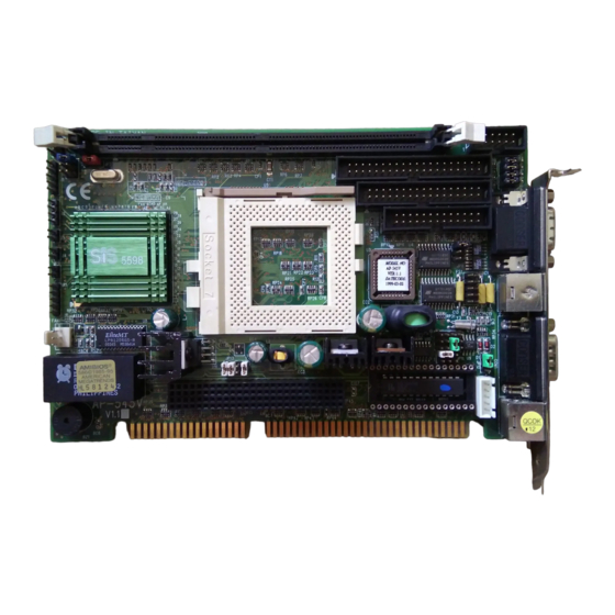
CHAPTER 2. JUMPER SETTINGS AND CONNECTORS 2.1 B AP-545V OARD UTLINE OF The Figure below shows the jumpers and connectors location on the AP-545V: AP-545V DIMM1 COM2 IDE1 FDC1 VGA1 PRT1 5598 PMS1 FAN1 JP10 COM1 JP12 JP13 JP11 BAT1... -
Page 11: 2.2 Cpu I
A pair of needle-nose pliers is recommended when working with jumpers. If you have any doubts about the best hardware configuration for your application, contact your local sales representative before you make any changes. In general, you simply need a standard cable to make most connections. AP-545V/5... -
Page 12: Jumperl
JUMPER SETTING AND CONNECTORS 2.4 J AP-545V UMPER OCATION FOR AP-545V JP10 JP12 JP13 JP11 AP-545V/6... -
Page 13: Jumpers
JUMPER SETTING AND CONNECTORS 2.5 J AP-545V UMPER ETTINGS UMMARY FOR JUMPERS LOCATION FUNCTION Select Internal CPU Clock Ratio Select External CPU Clock Select External VGA Function JP4 ~ JP8 Select Serial Port#2 Type JP10 Select Watch-Dog Time Out Period... - Page 14 JUMPER SETTING AND CONNECTORS 2.6 J AP-545V UMPER ETTINGS FOR CPU Speed Reference Table CPU Speed (MHz) Clock setting 66.6 66.6 66.6 66.6 66.6 Frequency ratio l JP1 : Select Internal CPU Clock Ratio Clock Ratio 1.5 X 1.5X 2.0 X 2.0X...
- Page 15 60 MHz 66.6 MHz (Default ) 60MHz 75 MHz 3-4 , 5-6 66.6MHz 83.3 MHz 1-2 , 3-4 Default : 75MHz 83.3MHz l JP3 : Select Internal VGA Function VGA Chips Disable Enable ( Default ) Disable Default : Enable AP-545V/9...
- Page 16 JUMPER SETTING AND CONNECTORS l JP4~JP8 : Select Serial Port#2 Type COM2 Type RS-232 ( Default ) RS-422 RS-485 Default : RS-232 RS-422 RS-485 AP-545V/10...
- Page 17 M-System Address JP11 C8000~CFFFF C8000~CFFFF D0000~D7FFF JP11 JP11 D8000~DFFFF D0000~D7FFF ; Note : Spare Jumper at 2-4 M-System address C8000 is already occupied by VGA BIOS ; therefore only D0000 and D8000 addresses are free. D8000~DFFFF Default : JP11 JP11 AP-545V/11...
- Page 18 JUMPER SETTING AND CONNECTORS JP12 : Select Watch-Dog Function Function JP12 JP12 JP12 Active By Reset System ( Default ) Active By Reset System Active By NMI System Disable Watch-Dog Active By NMI System Default : Disable JP12 Watch-Dog JP12 AP-545V/12...
- Page 19 3.4 V 3-4 , 5-6 , 7-8 3.0V 3.5 V 1-2 , 3-4 , 5-6 , 7-8 3.1V Default : 3.2V 7 5 3 1 3.3V JP13 8 6 4 2 3.4V Note : Spare Jumper at 2-4 3.5V AP-545V/13...
- Page 20 JUMPER SETTING AND CONNECTORS 2.7 I/O C AP-545V ONNECTOR OCATION FOR AP-545V COM2 IDE1 FDC1 VGA1 PRT1 PMS1 FAN1 COM1 PKB1 AP-545V/14...
-
Page 21: I/O Connectors
JUMPER SETTING AND CONNECTORS 2.8 I/O C AP-545V ONNECTOR UMMARY FOR CONNECTOR FUNCTION ACPI LED Power LED & Keyboard Lock Connector Ext. Speaker Connector IDE Active LED Connector Reset Connector FAN1 FAN Connector VGA1 VGA Monitor Connector IDE1 PCI IDE Interface Connector... - Page 22 ACPI Signal J1 : Power LED & Keyboard Connector Power LED VCC Keyboard Lock Signal J2 : Ext. Speaker Connector Speak Out Signal J3 : IDE Active LED Connector IDE Active Signal J4 : Reset Connector Reset Input Signal AP-545V/16...
- Page 23 FAN1 : FAN Connector PIN NO. DESCRIPTION Ground +12V FAN1 l VGA1 : VGA Monitor Connector PIN NO. DESCRIPTION Red Color Signal Green Color Signal Blue Color Signal Ground Ground Ground Ground Ground DDC-Data H-Sync. V-Sync. DDC-Clock VGA1 AP-545V/17...
- Page 24 Data 3 Data 12 Data 2 Data 13 Data 1 Data 14 Data 0 Data 15 Ground DMA REQ# Ground IOW# Ground IOR# Ground IOCHRDY Ground DMA ACK# Ground IRQ# Ground HDC CS0# HDC CS1# HDD Active Ground IDE1 AP-545V/18...
- Page 25 JUMPER SETTING AND CONNECTORS l IR1 : IrDa Connector PIN NO. DESCRIPTION IR_RX Ground IR_TX l KCN1 : 5 PIN Keyboard Connector ( Header ) PIN NO. DESCRIPTION Keyboard Clock Keyboard Data Ground KCN1 AP-545V/19...
- Page 26 PKB1 : PS/2 Keyboard Connector ( Mini Din ) PIN NO. DESCRIPTION PS/2 Keyboard Data Ground PS/2 Keyboard Clock PKB1 l PMS1 : PS/2 Mouse Connector ( Mini Din ) PIN NO. DESCRIPTION PS/2 Mouse Data Ground PS/2 Mouse Clock PMS1 AP-545V/20...
- Page 27 Transmit Data ( TXD ) Data Terminal Ready ( DTR# ) Ground ( GND ) Data Set Ready ( DSR# ) Request To Send ( RTS# ) Clear To Send ( CTS# ) Ring Indicator ( RI# ) COM1 AP-545V/21...
- Page 28 Data 2 Data 3 Data 4 Data 5 Data 6 Data 7 Acknowledge # Busy Paper Empty Printer Select Auto Form Feed # Error # Initialize # Printer Select IN # Ground Ground Ground Ground Ground Ground Ground Ground PRT1 AP-545V/22...
- Page 29 Drive Select A# Ground Motor Enable B# Ground Direction # Ground Step # Ground Write Data # Ground Write Gate # Ground Track 0# Ground Write Protect # Read Data # Ground Head Side Select # Disk Change # FDC1 AP-545V/23...
- Page 30 AD10 AD30 PREQ3# AD28 PREQ0# AD26 AD24 AD31 Ground Ground PGNT3# AD29 Ground Ground Ground AD22 AD27 Ground AD20 AD25 AD18 C/BE3# REQ64# AD16 AD23 ACK64# FRAME# AD21 Ground Ground Ground TRDY# AD19 Clock2 Ground Clock0 AD17 Ground Clock3 AP-545V/24...
- Page 31 Turn on the power of the computer system and press <Del> immediately. If you don’t have the chance to respond, reset the system by simultaneously typing the <Ctrl>, <Alt> and <Delete> keys, or by pushing the ‘ Reset ’ button on the system cabinet. You can also restart by turning the system OFF then ON. AP-545V/25...
- Page 32 : Exit the utility. ARROW KEYS : Use arrow keys á â to move cursor to your desired selection. <F10> : Saves all changes made to Setup and exits program. <F2> / <F3> : Changes background and foreground colors. AP-545V/26...
- Page 33 When you click on the option, the following parameters are listed as: Type, LBA/Large Mode, Block Mode, 32Bit Mode, and PIO Mode. All parameters are related to IDE drives except Type . Configuring an MFM Drive : If configuring an old MFM hard disk drive, you must know the drive AP-545V/27...
- Page 34 IDE drives have more sectors per track. Configuring IDE Drives : If the hard disk drive to be configured is an IDE drive, select the appropriate drive icon (Pri Master, Pri Slave). Select the IDE Detect icon to automatically detect all AP-545V/28...
- Page 35 Configuring a CD-ROM Drive : Select the appropriate drive icon (Pri Master, Pri Slave). Choose the Type parameter and select CDROM. You can boot the computer from a CD-ROM drive. You can also choose Auto and let AMIBIOS automatically set the correct drive parameters. AP-545V/29...
- Page 36 1024 65535 1024 77MB 1024 1024 68 MB 41 MB 25 MB 57 MB 41 MB 41 MB 41 MB 48 MB 65535 69 MB 65535 114 MB 1224 65535 1223 152 MB USER-DEFINED HARD DRIVE Enter user-supplied parameters AP-545V/30...
- Page 37 Boot Device : 1st ~ 4th Boot Devices are the options that set the sequence of boot drives (FLOPPY, IDE-0, CDROM, or LS-120) that the AMIBIOS attempts to boot from after AMIBIOS POST completes. To select the devices, please refer to Available options. AP-545V/31...
-
Page 38: Settings
On or Off . The default settings are On . Floppy Drive Swap : Set this option to Enabled to permit drives A: and B: to be swapped. The settings are Enabled or Disabled . The default settings are Disabled . AP-545V/32... - Page 39 HDD Access Control : Predefined setting is Normal. PS/2 Mouse Support : When this option is set to Enabled , AMIBIOS supports a PS/2-type mouse. The settings are Enabled or Disabled . The default settings are Disabled . System Boot Up Sequence. AP-545V/33...
- Page 40 Neither L1 internal cache memory on the CPU or L2 secondary cache memory is enabled. WriteBack Use the write-back caching algorithm. (default) WriteThru Use the write-through caching algorithm. External Cache : This option specifies the caching algorithm used for L2 secondary (external) cache memory. The settings are: Setting Description AP-545V/34...
- Page 41 The default setting is Cache. In the AMIBIOS for the Intel Triton chipset, the E000h page is used as ROM during POST, but shadowing is disabled and the ROM CS# signal is disabled to make the E000h page available on the local bus. AP-545V/35...
- Page 42 In the ‘Advanced Chipset Setup’ page, all options are predefined by the system board designer. Any attempt to change the parameter of the fields are not recommended. To continue this page, please move your cursor downwards to seek for other options. AP-545V/36...
- Page 43 MEMORY HOLE at 15M – 16M Disabled USB Function Disabled USD Keyboard/Mouse Legacy Support Disabled -¯ On Chip VGA Enabled ESC : Exit : Sel VGA Shard Memory Size PgUp/PgDn : Modify VGA Frequency 50 Mhz F2/F3 : Color AP-545V/37...
- Page 44 Power Management / APM : Set this option to Enabled to enable the power management and APM (Advanced Power Management) features. The settings are Enabled or Disabled . The default setting is Disabled . Instant ON Support : Set this option to Enabled to allow the computer to go to full power on AP-545V/38...
- Page 45 AMIBIOS. When any activity occurs, the computer enters Full On mode. Each of these options can be set to Monitor or Ignore . The default setting for all options is Ignore . AP-545V/39...
- Page 46 : Monitor IRQ4 (COM1/COM3) : Monitor IRQ5 (LPT2) : Ignore IRQ7 (LPT1) : Ignore IRQ9 : Ignore IRQ10 : Ignore IRQ11 : Ignore IRQ12 (PS2 Mouse) : Ignore IRQ13 (Math Coprocessor) : Ignore IRQ14 : Monitor IRQ15 : Monitor AP-545V/40...
-
Page 47: Pci Plug And 3.8 Peripheral
Plug and Play-aware. AMIBIOS only detects and enables PnP ISA adapter cards that are required for system boot. The Windows 95 operating system detects and enables all other PnP-aware adapter cards. Windows 95 is PnP-aware. Set this option to No if the operating system (such as DOS, AP-545V/41... - Page 48 IDE channel on the offboard PCI IDE controller. The settings are Disabled, INTA, INTB, INTC, or INTD . The Optimal and Fail-Safe default settings are Disabled . IRQ 3 IRQ 7 IRQ 11 IRQ 14 IRQ 4 IRQ 9 IRQ 12 IRQ 15 AP-545V/42...
- Page 49 IRQ pool is determined by reading the ESCD NVRAM. If more IRQs must be removed from the pool, the end user can use these PCI/PnP Setup options to remove the IRQ by assigning the option to the ISA/EISA setting. Onboard I/O is configurable by AMIBIOS. The IRQs used by onboard I/O are configured as PCI/PnP . AP-545V/43...
- Page 50 Reserved Memory Address : This option specifies the beginning address (in hex) of the reserved memory area. The specified ROM memory area is reserved for use by legacy ISA adapter cards. The settings are C0000, C4000, C8000, CC000, D4000, D8000 , or DC000 . The Optimal and Fail-safe default settings are C0000. AP-545V/44...
- Page 51 Onboard Serial PortA : This option enables serial port A on the motherboard and specifies the base I/O port address for serial port A. The settings are 3F8h, 3E8h , or Disabled . The Optimal default setting is 3F8h . The Fail-Safe default setting is Disabled . AP-545V/45...
- Page 52 Parallel Port DMA Channel : This option is only available if the setting for the Parallel Port Mode option is ECP . The settings are Disabled, DMA CH (channel) 0, DMA CH 1, or DMA CH 3 . The default setting is N/A . AP-545V/46...
- Page 53 WINBIOS Setup is executed, using either or both the Supervisor password or User password. AMIBIOS Password Support : The Supervisor and User icons activate two different levels of AP-545V/47...
- Page 54 The settings are Enabled or Disabled. If enabled, the following appears when a write is attempted to the boot sector. You may have to type N several times to prevent the boot sector write. Boot Sector Write!!! Possible VIRUS: Continue (Y/N)? _ AP-545V/48...
-
Page 55: Utility
Fail-Safe icon from the Default section of the WINBIOS Setup main menu. The Fail-Safe settings provide far from optimal system performance, but are the most stable settings. Use this option as a diagnostic aid if the system is behaving erratically. AP-545V/49... - Page 56 For example, if you want to Set 4 seconds for the time-out, you should set JP9: 4L ON and JP16 : 1-2 ON to enable watch-dog timer. C:\DOS> DEBUG -i443 EX.2: For assemble Language Enable : MOV DX, 443H IN AL, DX Disable : IN AL, 441H AP-545V/50...
- Page 57 MDA Video Card (Including LPTO) 3C0 - 3CF EGA Card 3D0 - 3DF CGA Card 3E8 - 3EF Serial Port #3 (COM 3) 3F0 - 3F7 Floppy Disk Controller 3F8 - 3FF Serial Port #1 (COM 1) Enable Watch-dog Timer Operation (read) AP-545V/51...
- Page 58 Real time clock IRQ 9 Software redirected to INT 0AH (IRQ 2) IRQ 10 Reserved IRQ 11 Reserved IRQ 12 PS/2 Mouse IRQ 13 Math Coprocessor (CPU Internal) IRQ 14 Primary Hard disk IRQ 15 Secondary Hard Disk Parity Check Error AP-545V/52...
- Page 59 APPENDIX C. PATENT PCI PIGGYBACK MODULE INSTALLATION There are two steps to install out patent PCI pigyback module on AP-545V Single Board Computer. Step 1. Plug the Dual Side Male Connector into the patent PCI piggyback female connector. Step 2. Plug the PCI module‘s female connector into the AP-545V male connector.
- Page 60 Although three main buses (data bus, address bus, and control bus) manage the computer’s operation, often these are collectively called the bus. The bus carries instructions back and forth between the CPU and other devices in the system. ISA, GLOSSARY AP-545V/54...
- Page 61 EISA or MCA Bus – Data is transmitted along 32 data lines to adapter cards designed specifically to work with the 32-bit buses. MCA expansion slots cannot accept 8-bit or 16-bit adapter cards. EISA stands for Extended Industry Standard Architecture, while MCA stands for MicroChannel Architecture. MCA is architecture used in IBM Microcomputer. AP-545V/55...
- Page 62 ”. Capacitate keyboard has a spring that causes the plastic and the metal plunger to move nearer to two pads that have large plates (plated in tin, nickel, and copper). These pads are connected to the keyboard’s printed circuit board. Hard AP-545V/56...
- Page 63 A serial port sends data one bit at a time over a single one-way wire; a parallel port can send several bits of data across eight parallel wires simultaneously. Take note that a serial connection sends a single AP-545V/57...
- Page 64 RS-232 port . SCSI (Small Computer System Interface) – An intelligent bus for transmitting data commands between a variety of devices. There are many implementations of SCSI, including Fast SCSI, Wide AP-545V/58...
- Page 65 SCSI, Fast Wide SCSI, Fast-20, and Fast-40. AP-545V/59...
- Page 66 The Windows OS provides medium text & graphics standard. VL-Bus – It is also known as Local Bus; this is an I/O interface that is directly connected and depended of the system CPU. The VL-Bus is an abbreviation of VESA Local Bus. AP-545V/60...
- Page 67 Terms and Conditions Date:1997.10.20 Warranty Policy 1. All products are warranted against defects in materials and workmanship on a period of two years from the date of purchase by the customer. 2. The buyer will bear the return freight charges for goods that are returned for repair within the warranty period whereas manufacturer will bear the other way after repair.
- Page 68 RMA Service Request Form Date:1997.10.20 When requesting RMA service, please fill out this “RMA Service Request Form”. This form needs to be shipped with your returns. Service cannot begin until we have this information. Company: Person to contact: Phone No. Purchased Date: Fax No.: Applied Date:...
- Page 69 Authorized Signatures Authorized Signatures...
Need help?
Do you have a question about the AP-545V and is the answer not in the manual?
Questions and answers