Advertisement
Quick Links
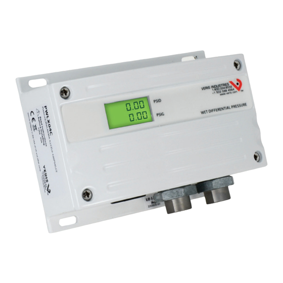
VERIS INDUSTRIES
PW SerieS
NOTICE
• This product is not intended for life or safety applications.
• Do not install this product in hazardous or classified locations.
• Read and understand the instructions before installing
this product.
• Turn off all power supplying equipment before working on it.
• The installer is responsible for conformance to all applicable codes.
ProDuct iDentification
Local Display
NIST
Operational Range
PW
L = LCD Display
N = NIST
X = No Display
X = None
1
Select operational range according to maximum gauge pressure, NOT differential pressure.
Example: High gauge pressure=90 psig, Select 100 psig model (04).
2
barg models use BSPT threads on sensor fittings.
Not available with barg units.
3
Dimensions
LOW
5.8"
(147 mm)
Z202882-0T
PAGE 1
Alta Labs, Enercept, Enspector, Hawkeye, Trustat, Veris, and the Veris 'V' logo are trademarks or registered trademarks of Veris Industries, L.L.C. in the USA and/or other countries.
environmental SenSorS
™
1
US or EU
03 = 0-50 psig
S = Standard
3
04 = 0-100 psig
C = CE
05 = 0-250 psig
06 = 0-3.5 barg
2
07 = 0-7.0 barg
2
08 = 0-17 barg
2
2.2"
(57 mm)
4"
(102 mm)
WET DIFFERENTIAL PRESSURE
HIGH
©2010 Veris Industries USA 800.354.8556 or +1.503.598.4564 / support@veris.com
PW SerieS
Wet Media Differential Pressure Transducer
Installer's Specifications
Media Compatibility
Input Power
Maximum Current Draw
Output
Pressure Ranges:
0-50 psig
0-100 psig
0-250 psig
0-3.5 barg
available
0-7.0 barg
0-17 barg
Status Indication
Proof Pressure
Burst Pressure
Accuracy at 25°C*
Surge Damping
Temperature Compensated Range
Sensor Operating Range
Long Term Stability
Zero Adjust
Operating Environment
Fittings
Physical
To conform to EMC Standards, use shielded cabling. Technical information is available from the
factory on request or on our website (www.veris.com/ce)
† Minimum input voltage for 4-20mA operation:
250 Ω loop (1-5V) = 12 VDC
500 Ω loop (2-10V) = 15 VDC
Minimum input voltage for volt operation:
0-5VDC output = 12 VDC
0-10VDC output = 15 VDC
* Accuracy combines linearity, hysteresis, and repeatability.
** F.S. is defined as full span of selected range in bidirectional mode.
quick install
The PW Series sensor is designed to accept high differential pressure. Install the
sensor on a duct or pipe across a pump, filter, heat exchanger, compressor, or other
non-corrosive wet media. The dual sensor design eliminates the need for a bypass
valve, and the bi-directional capability reduces installation errors. A pushbutton
allows easy zero adjustment.
1.
Mount sensor on a duct or pipe, across a pump, filter, or other pressure differential.
2.
Wire as shown (see page 2).
3.
Configure the jumpers (see page 2).
inStallation GUiDe
3-wire transmitter; user-selectable 4-20mA/0-5V/0-10V†
Dual color LED: solid green = normal, blinking green = low>high,
solid red = over range, blinking red = over pressure
Ranges A, B, C: ±1% F.S.**
Electronic; 5-second averaging
TC Zero <1.5% of product F.S. per sensor;
TC Span <1.5% of product F.S. per sensor
Pushbutton auto-zero and digital input (2-position terminal block)
-10° to 55°C (14° to 131°F); 10-90% RH noncondensing
psig models: 1/8" NPT female thread, stainless steel 17-4 PH
barg models: 1/8" BSPT female thread, stainless steel 17-4 PH
White powder-coated aluminum
17-4 PH stainless steel
12 to 30VDC, 24VAC nom.
DC: 125mA; AC: 280mA
5/10/25/50 psid
10/20/50/100 psid
25/50/125/250 psid
0.35/0.7/1.75/3.5 bard
0.7/1.4/3.5/7.0 bard
1.7/3.4/8.5/17.0 bard
2x max. F.S. range
5x max. F.S. range
Range D: ±2% F.S.**
0° to 50°C (32° to 122°F);
-20° to 85°C (-4° to 185°F)
±0.25%
08102
Advertisement

Related Manuals for Veris Industries PW Series


Summary of Contents for Veris Industries PW Series
- Page 1 Z202882-0T PAGE 1 ©2010 Veris Industries USA 800.354.8556 or +1.503.598.4564 / support@veris.com 08102 Alta Labs, Enercept, Enspector, Hawkeye, Trustat, Veris, and the Veris ‘V’ logo are trademarks or registered trademarks of Veris Industries, L.L.C. in the USA and/or other countries.
- Page 2 Z202882-0T PAGE 2 ©2010 Veris Industries USA 800.354.8556 or +1.503.598.4564 / support@veris.com 08102 Alta Labs, Enercept, Enspector, Hawkeye, Trustat, Veris, and the Veris ‘V’ logo are trademarks or registered trademarks of Veris Industries, L.L.C. in the USA and/or other countries.
Need help?
Do you have a question about the PW Series and is the answer not in the manual?
Questions and answers