Table of Contents
Advertisement
Quick Links
Advertisement
Table of Contents

Related Manuals for Barco SP4K-B


Summary of Contents for Barco SP4K-B
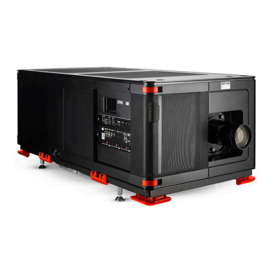
- Page 1 SP4K-B Installation manual ENABLING BRIGHT OUTCOMES...
- Page 2 Barco NV Beneluxpark 21, 8500 Kortrijk, Belgium www.barco.com/en/support www.barco.com Registered office: Barco NV President Kennedypark 35, 8500 Kortrijk, Belgium www.barco.com/en/support www.barco.com...
- Page 3 Changes Barco provides this manual 'as is' without warranty of any kind, either expressed or implied, including but not limited to the implied warranties or merchantability and fitness for a particular purpose. Barco may make improvements and/or changes to the product(s) and/or the program(s) described in this publication at any time without notice.
-
Page 5: Table Of Contents
Exhaust adapters (optional)..............................38 3 Installation process....................................39 Installation process overview ..............................40 4 Physical installation projector ..............................41 Positioning the SP4K-B ................................42 Accessing the power connections............................45 Power input configuration of the projector ........................46 Connecting the projector with the power net ........................48 Connecting a UPS with the projector electronics......................50 Connecting the external cooler ...............................52... - Page 6 Removal of the top cover................................. 135 12.9 Mounting the top cover ................................136 12.10 Mounting the light source side cover ..........................137 12.11 Mounting the sealed compartment side cover......................138 12.12 Mounting the operator side cover ............................139 R5912128 /03 SP4K-B...
- Page 7 12.15 Mounting the front cover ................................143 A Dimensions......................................145 Dimensions of the projector ..............................146 Dimensions of the universal pedestal..........................147 Dimensions of the external cooler ............................148 Glossary ........................................149 List of tools ....................................... 151 Index ..........................................153 R5912128 /03 SP4K-B...
- Page 8 R5912128 /03 SP4K-B...
-
Page 9: Safety
“warnings” and “cautions” are given depending on the procedure. Read and follow these “warnings” and “cautions” as well. Clarification of the term “SP4K-B” used in this document When referring in this document to the term “SP4K-B” means that the content is applicable for following Barco products: •... -
Page 10: General Considerations
• Before operating this equipment please read this manual thoroughly and retain it for future reference. • Installation and preliminary adjustments should be performed by qualified Barco personnel or by authorized Barco service dealers. • All warnings on the projector and in the documentation manuals should be adhered to. - Page 11 The DLP Cinema Systems are intended "FOR PROFESSIONAL USE ONLY" by AUTHORIZED PERSONNEL familiar with potential hazards associated with high voltage, high intensity light beams generated by lasers. Only qualified SERVICE PERSONNEL and TRAINED PROJECTIONISTS, knowledgeable of such risks, are allowed to perform service functions inside the product enclosure. R5912128 /03 SP4K-B...
-
Page 12: Important Safety Instructions
Lightning - For added protection for this video product during a lightning storm, or when it is left unattended and unused for long periods of time, remove all power from the projector. This will prevent damage to the projector due to lightning and AC power-line surges. R5912128 /03 SP4K-B... - Page 13 In the event of fire, use sand, CO or dry powder fire extinguishers. Never use water on an electrical fire. Always have service performed on this projector by authorized Barco service personnel. Always insist on genuine Barco replacement parts. Never use non-Barco replacement parts as they may degrade the safety of this projector.
- Page 14 Therefore a liquid cooling system is provided consisting of liquid circuits inside the SP4K-55B which are connected via hoses to external coolers. Only cooler models and hoses exclusively developed for this application and approved by Barco are allowed to be used. •...
- Page 15 Replacement parts: When replacement parts are required, be sure the service technician has used original Barco replacement parts or authorized replacement parts which have the same characteristics as the Barco original part. Unauthorized substitutions may result in degraded performance and reliability, fire, electric shock or other hazards.
-
Page 16: Product Safety Labels
警告!勿观看光束 眼睛勿直接接触可允许暴露的光束 RG3 IEC EN 62471- 5:2015 CLASS 1 IEC EN 60825-1:2014 危害距离:请参考安全手册 警告!請勿注視光源。禁止眼睛曝露在光源照射範圍。雷射危險等級 RG3 IEC EN 62471-5:2015 CLASS 1 IEC EN 60825-1:2014 安全危害距離:請參考安 全手冊。 Hazard RG3: optical radiation warning symbol Hazard RG3: not for household use symbol R5912128 /03 SP4K-B... - Page 17 ATTENTION DOUBLE PÔLE / FUSIBLE SUR LE NEUTRE HAUTE TENSION RÉSIDUELLE - ATTENTION : RISQUE DE CHOCS ÉLECTRIQUES. ÉTEINDRE ET DÉCONNECTER AVANT OUVERTURE DU COUVERCLE. LIRE LES INSTRUCTIONS AVANT DE RETIRER LE SMPS. Only for SP4K-55B Caution: Cable hot plugging is forbidden. R5912128 /03 SP4K-B...
-
Page 18: High Brightness Precautions: Hazard Distance
Separation Height. Projector. Separation Width. Based on national requirements, no person is allowed to enter the projected beam within the zone between the projection lens and the related hazard distance (HD). This shall be physically impossible by creating R5912128 /03 SP4K-B... - Page 19 The LIP shall be installed by Barco or by a trained and Barco-authorized installer or shall only be transferred to laser light show variance holders. This is applicable for dealers and distributors since they may need to install the LIP (demo install) and/or they transfer (sell, rent, lease) the LIP.
-
Page 20: Hd For Fully Enclosed Projection Systems
The light emitted from the screen within the observation shall never exceed the RG2 exposure limit, determined at 10 cm. The HD can be neglected if the measured light at the screen surface is below 5000 diffuse cd/m² or 15000 LUX. R5912128 /03 SP4K-B... -
Page 21: Hd In Function Of Modifying Optics
Safety 1.6 HD in function of modifying optics Hazard Distance SP4K-55B SP4K-40B SP4K-35B SP4K-27BHC Throw Ra o Image 1–4 R5912128 /03 SP4K-B... - Page 22 Safety R5912128 /03 SP4K-B...
-
Page 23: Getting Started
Barco provides a guarantee relating to perfect manufacturing as part of the legally stipulated terms of guarantee. Observing the specification mentioned in this chapter is critical for projector performance. -
Page 24: Installation Requirements
3 500 11 483 4 000 13 123 Main Power requirements Depending on the available power circuit, all SP4K-B projectors can operate from a single-phase power net or three-phase power net. Power system Power requirements three-phase power net 55B / 40B / 27BHC: •... - Page 25 The SP4K-B does not have a built in UPS unit. Projector weight Do not underestimate the weight of the SP4K-B projector. The projector weights ±155 kg (±342 lbs) without lens and specific a SP4K-55B projector weights 175 kg (385 lbs) without lens. Ensure that the pedestal on which the projector is installed is capable of supporting the complete load of the system.
-
Page 26: Unpacking The Projector
Hoisting or lifting tool Required parts Eye bolts M10 x 4 How to unpack the SP4K-B projector Remove the strapping bands from the packaging. Use a cutting tool (e.g. side cutter, knife, etc.) to carefully cut the straps. Carefully cut open the tape of the box and open it. - Page 27 Getting started Image 2–2 Removing foam, manuals and cardboard boxes Remove the outer cardboard box and any additional plates. Remove the inner top cover. Image 2–3 Remove both U-shaped plates and the four foam corner pieces. R5912128 /03 SP4K-B...
- Page 28 Make sure to provide a hoisting or lifting tool capable of lifting and moving the projector to its designated position. R5912128 /03 SP4K-B...
- Page 29 The projector is not delivered with a lens by default. If you also ordered a lens, it will be delivered in a separate box. For lens installation, see “Lenses and Lens holder”, page R5912128 /03 SP4K-B...
-
Page 30: Unpacking The External Cooler
Remove the strapping bands from the packaging. Use a cutting tool (e.g. side cutter, knife, etc.) to carefully cut the straps. Carefully cut open the tape of the box and open it. Take out the foam pieces. Remove the outer cardboard box. Image 2–7 Remove the lower foam pieces. R5912128 /03 SP4K-B... - Page 31 2 people to lift up the cooler and put it on its installation location. Save the original shipping carton and packing material, they will be necessary if you ever have to ship your cooler. For maximum protection, repack your cooler as it was originally packed at the factory. R5912128 /03 SP4K-B...
-
Page 32: Initial Inspection
This check should confirm that there are no broken knobs or connectors, that the cabinet and panel surfaces are free of dents and scratches, and that the operating panel is not scratched or cracked. The Barco Sales and Service office should be notified as soon as possible if this is not the case. -
Page 33: Conventions
Right side of the projector (User input side). Left side of the projector (Light source side). Back side of the projector. Front of the projector. External cooler for SP4K-55B Image 2–10 Left side cooler Right side cooler Front side cooler Top side cooler R5912128 /03 SP4K-B... -
Page 34: Air Flow
Air flow projector The SP4K-B projector has two air outlets and three air inlets. The air inlets are located on the front side and bottom side of the projector. The air outlets are located on the top and on the back side of the projector. - Page 35 Getting started Image 2–12 Air inlet right side of external cooler Air inlet left side of external cooler Air outlet of external cooler R5912128 /03 SP4K-B...
-
Page 36: Web Communicator
The Web Communicator application is a uniquely powerful and easy to use built-in web application for the Barco projector. This application provides all the necessary tools necessary to setup and control the connected projector. A comprehensive array of easy to access menu pages provide the projectors digital input, output and screen display via a combination of simple buttons and displays. -
Page 37: Web Commander
It is accessible via a web browser and is fully supported on iOS and Android devices. Image 2–14 The Web Commander has its own user guide, of which you can find the latest version on the Barco website. R5912128 /03 SP4K-B... -
Page 38: Exhaust Adapters (Optional)
These exhaust adapters allow the customer to fix an air extraction system to the projector, in order to extract hot air coming from the air outlets of the projector. Image 2–15 SP4K-B projector with both exhaust adapters mounted For all ordering information about options and accessories see Barco website. R5912128 /03 SP4K-B... -
Page 39: Installation Process
This chapter gives an overview of all the different stages in the installation process which you have to follow to get your SP4K-B projector up and running. Each stage is briefly described and refers to more detailed step by step procedures in this manual. -
Page 40: Installation Process Overview
Web Communicator and all of its features, please refer to the projector user guide. If you have a projector with ICMP-X and you want a more in-depth explanation on how to control this media player, please refer to the Web Commander user guide. R5912128 /03 SP4K-B... -
Page 41: Physical Installation Projector
Physical installation projector Positioning the SP4K-B .........................42 Accessing the power connections ....................45 Power input configuration of the projector ..................46 Connecting the projector with the power net..................48 Connecting a UPS with the projector electronics ................50 Connecting the external cooler ......................52 R5912128 /03 SP4K-B... -
Page 42: Positioning The Sp4K-B
WARNING: The installation of the projector requires at least 6 persons. General guide lines • Use a solid pedestal to put the SP4K-B projector on. Ensure that the pedestal can handle the weight of the projector and that all feet of the projector are captured. •... - Page 43 Later, when the projector is up-and-running, adjust precise image geometry and placement. Projector tilting In an ideal installation, the SP4K-B lens surface is centered with and parallel to the screen. This orientation helps to ensure optimized lens performances with minimal offset. If this position is not possible (such as when the projector is significantly higher than the center of the screen), it is better to rely on offset rather than extra tilt.
- Page 44 CAUTION: The projector may tilt a maximum of 12° forward and 3° backwards. This includes the tilt created by the projector feet and the tilt created by the pedestal. Barco offers a pedestal for the projector. This pedestal allows you to easily tilt the projector forward up to 6°.
-
Page 45: Accessing The Power Connections
Slightly loosen the two screws on the bottom of the net input cover (reference 1, Image 4–5). Use a T20 Torx screwdriver. Lift the net input cover up and away from the projector. Image 4–5 Removal of the net input cover R5912128 /03 SP4K-B... -
Page 46: Power Input Configuration Of The Projector
Take off the four mounted links (A, B, C and D). Mount the links as illustrated, depending on the configuration: 1. Y configuration: Connect the upper pins with each other. Place two links between each pin (do not remove them). R5912128 /03 SP4K-B... - Page 47 3. Mono phase configuration: Spread the four links over the six pins as illustrated. Make sure both the upper and lower pins are connected with each other. Image 4–10 Mono phase configuration Turn a nut on each pin and secure with a torque wrench set to 3.5 Nm. R5912128 /03 SP4K-B...
-
Page 48: Connecting The Projector With The Power Net
CAUTION: ALL POWER CONNECTIONS to the SP4K-B projector are made to the five-terminal strip located on the mains board behind the operator side cover and mains cover of the projector. - Page 49 Secure the AC power cord by fastening the cable gland (reference 3). Use a 30 mm open-end wrench. Place the net input cover back and seal it. Tighten the two screws (reference 1), using a T20 Torx screwdriver. R5912128 /03 SP4K-B...
-
Page 50: Connecting A Ups With The Projector Electronics
4.5 Connecting a UPS with the projector electronics WARNING: Only use UPS units which are suitable for the SP4K-B series projector. See chapter Installation requirements, for more information about the requirements of the UPS. CAUTION: The electrical connection with the UPS INLET socket of the projector must be done with a certified AC power supply cord (minimum 1.50 mm²... - Page 51 Secure the AC power cord by fastening the cable gland (reference 3). Use a 24 mm open-end wrench. Place the net input cover back and seal it. Tighten the two screws (reference 1), using a T20 Torx screwdriver. R5912128 /03 SP4K-B...
-
Page 52: Connecting The External Cooler
When no external cooler is connected with the projector, the projector may only be used on 75% of its maximum light output. Otherwise irreversible damage can take place. Available tube & cable kits Barco offers 2 kits with different length: • R9802034 : tube & cable kit with a length of 2.5 m •... - Page 53 Physical installation projector Projector to External cooler OUT1 OUT1 OUT2 OUT2 When disconnecting the cable, always mount the plastic cover over the connector. R5912128 /03 SP4K-B...
- Page 54 Physical installation projector R5912128 /03 SP4K-B...
-
Page 55: Lenses And Lens Holder
About this chapter This chapter gives an overview of available lenses for the SP4K-B projector, using both variants of the lens holder. It also explains how you can select the best suited lens for your specific situation using the lens calculator. -
Page 56: Available Lenses
This list only takes into account active lenses at the moment of release of this manual. Lenses that have become end-of life or end-of service are not taken into account. Consult the Barco website for the most up-to-date information on active lenses. -
Page 57: Lens Selection
Lenses and Lens holder 5.2 Lens selection Which lens do I need? Browse to Barco's website on www.Barco.com. Go to the product page of the desired product. On the product page, go to the Tools section and click Lens calculator. -
Page 58: Installation Of A Lens
Take the lens assembly out of its packing material and remove the lens caps on both sides. Gently insert the lens in such a way that the lens connector matches the socket (reference 2). R5912128 /03 SP4K-B... - Page 59 Ensure the lens touches the front plate of the lens holder. Image 5–5 Locking the lens Check if the lens is really secured by trying to pull the lens out of the lens holder. R5912128 /03 SP4K-B...
-
Page 60: Removal Of A Lens From The Lens Holder
Gently pull the lens out of the lens holder. Image 5–7 Lens removal It's recommended to place the lens caps of the original lens packaging back on both sides of the removed lens to protect the optics of the lens. R5912128 /03 SP4K-B... - Page 61 Lenses and Lens holder It is recommended to place the dust cover of the original projector packaging back into the lens opening to prevent intrusion of dust. Image 5–8 R5912128 /03 SP4K-B...
-
Page 62: Lens Shift, Zoom And Focus
Lenses and Lens holder 5.5 Lens shift, zoom and focus Motorized lens adjustment The SP4K-B projector is equipped with a motorized lens shift functionality and a motorized zoom & focus functionality. About the shift range The lens can be shifted with respect to the internal optics of the projector (DMD) which results in a shifted image on the screen (Off-Axis). - Page 63 The operation temperature of the lens is reached after approximately 30 minutes projection of average video. If it becomes impossible to focus the image, perform a Scheimpflug adjustment. For more info on this, refer to “Scheimpflug adjustment”, page R5912128 /03 SP4K-B...
-
Page 64: Scheimpflug Introduction
Image 5–14 Scheimpflug adjustments points on Lens holder - Projector front view. (Shape of the lens may vary with the model) Scheimpflug adjustment screw Lock screw Scheimpflug adjustment screw Lock screw Scheimpflug adjustment screw Projector top side Lock screw Projector Right side R5912128 /03 SP4K-B... -
Page 65: Scheimpflug Adjustment
5–16) of the Lens Holder . Use a 8 mm Allen wrench for the lock screws. Optimize the focus of the projected image in the center of the screen (F) using the focus buttons in the “Control – Light, Dowser, Lens menu”. Image 5–16 Center focusing R5912128 /03 SP4K-B... - Page 66 Sharpen the image at the top center of the screen by turning the lower Scheimpflug adjustment screw (reference 3 Image 5–19). Image 5–19 Top focusing Optimize the focus of the projected image in the center of the screen using the focus buttons in the “Control – Light, Dowser, Lens menu”. Image 5–20 R5912128 /03 SP4K-B...
- Page 67 Scheimpflug procedure. This can be fixed by adjusting the adjustment points in such a way the lens holder is returned to its nominal position. In order to do so, consult the service manual. R5912128 /03 SP4K-B...
- Page 68 Lenses and Lens holder R5912128 /03 SP4K-B...
-
Page 69: Input & Communication
This chapter describes the functionality of the touch display, as well as the different input and communication ports of your projector. Note that all information about the ICMP-X is gathered into one separate chapter. See “ICMP-X”, page R5912128 /03 SP4K-B... -
Page 70: Introduction
General The Input & Communication side of the SP4K-B consists of a touch display and a card cage with three slots. The touch display also functions as the “tail light”, which reflects the status of the projector. Note that all information about the ICMP-X is gathered into one separated chapter called ICMP-X. -
Page 71: Cinema Controller Of The Projector
(reference 2 Image 6–2) to connect the network which contains the DHCP server. The SP4K-B can be connected to a WAN (Wide area network) (reference 2 Image 6–2). Once connected to the WAN, users can access the projector from any location, inside or outside (if allowed) their company network using the Web Communicator software. - Page 72 If the only file on the USB device is the firmware file (a “*.fw” file), the projector will automatically start one of the following processes. • samba<version nr>.fw: The projector will upgrade or downgrade, depending on the version number. Make sure that any used USB-stick is FAT32 compatible and contains no other files or folders. R5912128 /03 SP4K-B...
-
Page 73: Icp-D (Integrated Cinema Processor - Direct)
Input & communication 6.3 ICP-D (Integrated Cinema Processor – Direct) In case the projector is equipped with a Barco ICMP-X no ICP-D board is inserted. All ICP-D functionality is integrated in the Barco ICMP-X. Introduction Depending on the projector configuration, the projector card cage is either equipped with an ICP-D or ICMP-X. - Page 74 Orange Update done When installing a new ICP board in a SP4K-B projector the Spatial Color Calibration file must be reloaded and activated. CAUTION: Make sure not to short circuit the battery on the board. That will destroy the board...
-
Page 75: Icmp-X
Furthermore, the status LEDs are described and the importance of the device certificate is illustrated. For the specifications on the “network streaming (Live IP)”, SDI and HDMI ports, please refer to the appendices of the ICMP-X installation manual. Image 7–1 R5912128 /03 SP4K-B... - Page 76 ICMP-X R5912128 /03 SP4K-B...
-
Page 77: Icmp-X Introduction
HDDs for ICMP-X As an integrated component of the projector, installation and maintenance of the ICMP-X requires the same skills and the same precautions as an intervention on the projector itself. For order info see www.barco.com. Front plate of the ICMP-X 0123456789 Image 7–3 Front plate ICMP-X... - Page 78 The Card Cage can be different depending the projector type but it generally consists of a button module and several removable units, which include the ICMP-X (reference 1) and the Barco Cinema Controller (reference ICMP-X location in the Card Cage of an SP4K and SP2K series projector.
-
Page 79: Icmp-X Hdd
The mounting order of the HDDs and the HDD slots do not matter. Of course, when using HDDs from another ICMP-X it is necessary to retrieve from the content distributor the KDMs corresponding to the content and the new ICMP-X. • Exchange of HDD set between two ICMP-Xs with a different storage controller: R5912128 /03 SP4K-B... - Page 80 GEN2 storage controller. Software version 1.4.2 or higher is needed. This list only takes into account supported HDD models validated by Barco at the moment this manual was published. The most update list is available in the installation manual of the ICMP-X...
-
Page 81: What Are The Possible Hdd Swaps
Web Communicator. (Spare part kit provided by • immediately usable after RAID • RAID initialization does not need Barco with a set of 3 hard initialization + restart (content to be performed. disks configured to GEN1 can be ingested). •... - Page 82 All content will be lost. RAID initialization needs to be perform with Communicator. 2. Unit has been upgraded with a GEN2 storage controller (+ ICMP software 1.4.2 or higher is installed): Content is preserved but certificates (KDM) need to be re-ingested. R5912128 /03 SP4K-B...
-
Page 83: Icmp-X Communication And Input Ports
USB 3.0 (2 ports) The ICMP-X can be connected to a USB 3.0 media device to load content. The USB port can be used to load content (DCP), keys (KDM) or software updates. R5912128 /03 SP4K-B... - Page 84 HDMI A / B HDMI 2.0 connector to connect a video source. 3G-SDI A / B SDI connector to connect a video source. R5912128 /03 SP4K-B...
-
Page 85: Icmp-X Status Leds
Security Manager - FPGA self-test Green Blinking Green Starting Applications Green Green Applications started in normal mode Green Orange Applications started in degraded mode Blinking Red FIPS error Green Blinking Orange Update ongoing Orange Orange Update done R5912128 /03 SP4K-B... -
Page 86: Icmp-X Hdd Status Leds
See procedure via the (Web) Commander. See user guide of the “Removing a HDD from the ICMP-X”, page (Web) Commander. “Installing a HDD into the ICMP-X”, page Ensure to insert the HDD firmly. 3. Switch on the power. R5912128 /03 SP4K-B... - Page 87 (Web) Communicator. Note that all content will be lost! 4. If problem remains contact Service for further instructions. In case the ICMP-X has to be returned to factory (e.g. for repair) the non defective HDDs should be removed and kept. R5912128 /03 SP4K-B...
-
Page 88: Icmp-X Device Certificate
Purpose of the ICMP-X device certificate The device certificate (*. pem) of the ICMP-X is a digital certificate signed by Barco which is required when ordering the KDM to play a DCP that is ingested on the ICMP-X. The device certificate is stored inside the ICMP-X and on a web server. - Page 89 DCI compliance web site. Notably, DCI compliance does not require compliance to the full set of SMPTE DCP standards. A copy of the most recent DCI specification can be downloaded from the DCI website (http://dcimovies.com). R5912128 /03 SP4K-B...
-
Page 90: Icmp-X Configuration Via Web Communicator
Verify internal clock of the ICMP-X. All installation and maintenance operations on the ICMP-X are performed via Web Communicator, the Barco configuration software. Please refer to the user guide for more information. Factory settings Restoring to factory setting is a feature that removes all settings performed on the ICMP-X and replaces them with the default values set at the factory. -
Page 91: Icmp-X Reset
ICMP restarts. Image 7–11 WARNING: Resetting the ICMP-X with the hardware reset button may cause damage to the content on the HDDs. A re-configuration of the whole system may be required! R5912128 /03 SP4K-B... -
Page 92: Obtaining The Icmp-X Certificate
Using control software to obtain the ICMP-X certificate Use your control software to download the ICMP-X certificate from the ICMP-X main board. For detailed instructions, refer to the user guide of your control software, or the projector User Guide. R5912128 /03 SP4K-B... -
Page 93: Removing A Hdd From The Icmp-X
Moving the latch towards the left. Image 7–13 Push the unlock button to open the handle. Image 7–14 Pull the HDD out of its slot. Image 7–15 To install an HDD, see the following procedure: “Installing a HDD into the ICMP-X”, page R5912128 /03 SP4K-B... -
Page 94: Installing A Hdd Into The Icmp-X
“Removing a HDD from the ICMP-X”, page CAUTION: Always use a new empty spare part HDD approved by Barco to replace a malfunction HDD. Do not use a HDD from another ICMP-X HDD set. CAUTION: Always make sure that all HDDs in the ICMP-X HDD set have the same storage capacity. - Page 95 200 GB per hour. Once the RAID is completed the red LED turns off. CAUTION: It's strongly recommended to complete the RAID recovery process prior to starting a show. This to ensure that the content integrity is preserved and that the show is not interrupted. R5912128 /03 SP4K-B...
- Page 96 ICMP-X R5912128 /03 SP4K-B...
-
Page 97: Projector Power Cycle
About the Projector Power Cycle This chapter contains the Switch ON and Switch OFF procedures for the SP4K-B projector. These procedures highlight all important points to be checked prior to switching the projector ON. This is to ensure a safe startup of the projector. -
Page 98: Explaining The Power States
Using the ECO menu on the touch display (if available). • Using the Power menu in Web Communicator. GPI3 works the same way as the power button. Thus take into account that sending a signal for more than 6 seconds will turn the projector OFF instead. R5912128 /03 SP4K-B... - Page 99 Projector Power Cycle Image 8–2 Location of the Power button and GPI 1-4 input on the Cinema Controller. Power state diagram FORCE SHUTDOWN START-UP >6sec SHUTDOWN 1 sec READY READY Image on the screen Image 8–3 Power State diagram R5912128 /03 SP4K-B...
-
Page 100: Switching The Projector On
Remotely, using GPI3 How to switch on locally, using the touch display? Ensure that the SP4K-B projector is installed onto a stable platform. Ensure the projector is correctly connected to the mains power. Ensure that the correct lens is installed for your application. - Page 101 Projector Power Cycle How to switch on remotely, using only Web Communicator? Ensure that the SP4K-B projector is installed onto a stable platform. Ensure the projector is correctly connected to the mains power. Ensure that the correct lens is installed for your application.
-
Page 102: Switching The Projector Off
Image 8–7 Example of the ECO menu on the touch display How to put the projector in ECO mode, using the Web Communicator? In the Communicator, browse to Control >> Power. In the Power menu, press Switch to ECO mode and confirm. R5912128 /03 SP4K-B... - Page 103 How to turn the projector OFF? Press the power button for more than six seconds. The projector will go to OFF mode. Send a signal via GPI3 for more than six second. The projector will go to OFF mode. R5912128 /03 SP4K-B...
- Page 104 Projector Power Cycle R5912128 /03 SP4K-B...
-
Page 105: Connectivity
Connectivity Connecting to the projector for the first time .................. 106 Software update ......................... 107 R5912128 /03 SP4K-B... -
Page 106: Connecting To The Projector For The First Time
IP address is by using a Bonjour program. The Bonjour software will display the SP4K-B projector as a combination of product key and the default hostname. In more detail, this is: •... -
Page 107: Software Update
9.2 Software update How to update the software Download the latest firmware from the Barco website. Click on myBarco and login to get access to secured information. Registration is necessary. If you are not yet registered, click on New to myBarco and follow the instructions. With the created login and password, it is possible to login where you can download the software. - Page 108 3. Take note: While rebooting, you will lose connection to the projector. 4. Once rebooted, every projector component will be updated to the version included in the software package. Take into account that it might take a while until all components have been updated. R5912128 /03 SP4K-B...
- Page 109 Connectivity Image 9–6 Example of the components update page. 5. Once every component has been updated, you will be redirected to the Web Communicator login page. R5912128 /03 SP4K-B...
- Page 110 Connectivity R5912128 /03 SP4K-B...
-
Page 111: Convergence
Take into account that opening the sealed compartment to perform convergence will automatically trigger one or more tamper warning messages. Do not forget to clear these messages after convergence has been completed. For more info, refer to “”, R5912128 /03 SP4K-B... -
Page 112: Opening The Sealed Compartment
Lift the cover up slightly using both lips. Then remove the cover by taking it away from the projector. Image 10–2 Sealed compartment side cover, remove Slightly slide the top cover a bit outwards. Then lift it up and remove it. R5912128 /03 SP4K-B... - Page 113 Convergence Image 10–3 Sealed top cover, remove R5912128 /03 SP4K-B...
-
Page 114: Closing The Sealed Compartment
Hook the cover plate onto the studs. Slide the cover downwards on both lips until it is in its correct position. Image 10–5 Sealed compartment side cover, mount Tighten the four screws of the side cover (reference 1). Use a T20 Torx screwdriver. R5912128 /03 SP4K-B... - Page 115 Convergence Image 10–6 Sealed cover fixation R5912128 /03 SP4K-B...
-
Page 116: Convergence Controls
Blue channel, knob number 1 Green channel, knob number 4 Blue channel, knob number 2 Green channel, knob number 5 Blue channel, knob number 3 Green channel, knob number 6 Exact position of the knobs can differ slightly R5912128 /03 SP4K-B... - Page 117 2 turns. Then return to the required nominal position. The dead zone should now be displaced away from the required end position. The DMD is now securely held in the nominal position. R5912128 /03 SP4K-B...
-
Page 118: Converging The Blue Pattern Onto The Red Pattern
Repeat from step 1 until full coincidence is obtained of the BLUE pattern in the center, left and right of the projected image. Continue with the procedure: “Converging the green pattern onto the red pattern”, page 119. R5912128 /03 SP4K-B... -
Page 119: Converging The Green Pattern Onto The Red Pattern
Repeat from step 1 until full coincidence is obtained of the GREEN pattern in the center, left and right of the projected image. If necessary repeat the blue convergence adjustment. For more info, see “Converging the blue pattern onto the red pattern”, page 118. R5912128 /03 SP4K-B... - Page 120 Convergence If all adjustments are finished, switch off the projector. Close the sealed compartment and reinstall all covers of the projector. R5912128 /03 SP4K-B...
-
Page 121: Color Calibration
11.3 Color gamut calibration ....................... 125 About this chapter This chapter briefly describes the luminance and color calibration process for the SP4K-B. Several references are made to the projector user guide, where more detailed instructions and menu navigations are available. -
Page 122: Calibration Process
1. First activate the INPUT file. 2. then activate the PCF file (PCF already contains plane 1 information), 3. then activate the MCGD and TCGD files. For more details on creating and using macros, see the projector user guide. R5912128 /03 SP4K-B... -
Page 123: White Point Calibration
Place a spectroradiometer in the auditorium. Position it in such a way it meets the following requirements. • Perpendicular to the screen. • In the auditorium sweet spot. • In such a way it can measure the reflected light from the center of the screen. R5912128 /03 SP4K-B... - Page 124 In the next screen, enter the x & y coordinates for the 2D measurement. Use the spectroradiometer to measure these values. Optionally, you can also click next to enter the x & y coordinates for 3D measurement, while using a 3D file. After white point calibration proceed immediately with color gamut calibration. R5912128 /03 SP4K-B...
-
Page 125: Color Gamut Calibration
(TCGD) of the film will introduce a color correction so that the film will be projected with the desired color target. Image 11–4 Correction of native color gamut towards desired color gamut (electronic correction) R5912128 /03 SP4K-B... - Page 126 In addition you can check if the corrected colors comply. To do so, browse to the Web Communicator and navigate to Configuration > Color calibration > Verify corrected colors. See the projector user guide for detailed instructions. R5912128 /03 SP4K-B...
-
Page 127: Projector Covers
WARNING: All procedures described in this chapter may only be performed by TRAINED PROJECTIONISTS or qualified SERVICE PERSONNEL. WARNING: Always switch off the projector and unplug the power cord before removing one of the covers, unless otherwise stated. R5912128 /03 SP4K-B... -
Page 128: Removal Of The
Slide the front cover to the side of the Input & Communication Unit and remove it. Note: The handles do not click open. They are fixed into the cover. Image 12–1 Sliding the front cover away from the projector R5912128 /03 SP4K-B... -
Page 129: Removal Of The Rear Cover
Slide the rear cover to the side of the Input & Communication unit and remove it. Note: The handles do not click open. They are fixed into the cover. Image 12–2 Sliding the rear cover away from the projector R5912128 /03 SP4K-B... -
Page 130: Removal Of The Mains Side Cover
Remove the two screws of the mains side cover. Use a T20 Torx screwdriver. Slide the side cover a bit towards the rear side of the projector. Lift up and remove the side cover. Image 12–3 Removal of the mains side cover R5912128 /03 SP4K-B... -
Page 131: Removal Of The Operator Side Cover
Remove the two screws at the top of the side cover. Use a T20 Torx screwdriver. Image 12–4 Removing the screws of the right side cover Tilt the upper side of the cover outwards and remove it. Image 12–5 Removing the side cover R5912128 /03 SP4K-B... -
Page 132: Removal Of The Sealed Compartment Side Cover
Remove the two screws of the sealed compartment side cover. Use a T20 Torx screwdriver. Lift up and remove the side cover. Tip: It may be necessary to move the cover a bit towards the rear side in order to properly remove it. Image 12–6 Removal of the mains side cover R5912128 /03 SP4K-B... -
Page 133: Removal Of The Light Source Side Cover
Remove the two screws at the top of the side cover. Use a T20 Torx screwdriver. Image 12–7 Removing the screws of the side cover Tilt the upper side of the cover outwards and remove it. Image 12–8 Removing the side cover Lift up the side cover and remove it. R5912128 /03 SP4K-B... -
Page 134: Removal Of The Small Rear Cover
How to remove Remove the top cover and rear cover. Loosen the screw on the top frame. Use a T20 Torx screwdriver. Lift up and remove the small cover as illustrated. Image 12–9 Removing the small rear cover. R5912128 /03 SP4K-B... -
Page 135: Removal Of The Top Cover
Note: There are several clips on the side bars of the projector in which the top cover is clicked in. Push the cover out of the clips to fully remove the top cover. Image 12–10 Removing the top cover R5912128 /03 SP4K-B... -
Page 136: Mounting The Top Cover
Carefully click the cover on the clips that are mounted on both side bars of the projector. This to make sure the top cover doesn’t move. Fasten the top cover with the four screws. Use a T20 Torx screwdriver. Image 12–11 Mounting the top cover R5912128 /03 SP4K-B... -
Page 137: Mounting The Light Source Side Cover
Image 12–12 Mounting the side cover Click the cover onto the cover receiver of the top frame (reference 2). Fasten the side cover with the two top screws. Use a T20 Torx screwdriver. Image 12–13 Tightening the screws of the side cover R5912128 /03 SP4K-B... -
Page 138: Mounting The Sealed Compartment Side Cover
“Mounting the light source side cover”, page 137. Place and slide down the sealed compartment side cover. Image 12–14 Removal of the mains side cover Fasten the side cover using the two screws of the mains side cover. Use a T20 Torx screwdriver. R5912128 /03 SP4K-B... -
Page 139: Mounting The Operator Side Cover
Tip: Place the cover in a slightly tilted angle so you can clearly see the hooks while mounting the cover. Image 12–15 Push the upper side of the cover towards the projector to close it. Image 12–16 Mounting the side cover Fasten the side cover with the two top screws. Use a T20 Torx screwdriver. R5912128 /03 SP4K-B... - Page 140 Projector Covers Image 12–17 Tightening the screws of the side cover R5912128 /03 SP4K-B...
-
Page 141: Mounting The Mains Side Cover
Make sure the light source side cover is mounted. Place and slide down the mains side cover. Image 12–18 Removal of the mains side cover Fasten the side cover using the two screws of the mains side cover. Use a T20 Torx screwdriver. R5912128 /03 SP4K-B... -
Page 142: Mounting The Rear Cover
Place the cover over the cover hook on the bottom of the projector frame (reference 1). Slide the clips in the rear cover over the cover hooks in the top of the frame (reference 2). Image 12–19 Sliding in the rear cover R5912128 /03 SP4K-B... -
Page 143: Mounting The
Place the cover over the cover hook on the bottom of the projector frame (reference 1). Slide the clips in the front cover over the cover hooks in the top of the frame (reference 2). Image 12–20 Sliding in the front cover R5912128 /03 SP4K-B... - Page 144 Projector Covers R5912128 /03 SP4K-B...
-
Page 145: A Dimensions
Dimensions Dimensions of the projector ......................146 Dimensions of the universal pedestal ................... 147 Dimensions of the external cooler ....................148 R5912128 /03 SP4K-B... -
Page 146: Dimensions Of The Projector
M10 (2X) CENTER OFGRAVITY AIR OUTLET 2 CENTER OF GRAVITY AIR INLET AIR INLET AIR OUTLET 1 221,44 42,5 Image A–1 All dimension given in mm Dimensions of the projector with the exhaust adapters 200 (2X) Image A–2 R5912128 /03 SP4K-B... -
Page 147: Dimensions Of The Universal Pedestal
Dimensions A.2 Dimensions of the universal pedestal Dimensions Image A–3 Dimensions given in millimeters. R5912128 /03 SP4K-B... -
Page 148: Dimensions Of The External Cooler
Dimensions A.3 Dimensions of the external cooler Dimensions Dimensions are given in millimeter. CENTER OF GRAVITY Image A–4 R5912128 /03 SP4K-B... -
Page 149: Glossary
To create the correct set of KDMs for a site requires knowledge of the digital certificate in the projection system´s media block. *.pem Privacy-enhanced Electronic Mail. File format used to distribute digital signed certificates. Base64 encoded certificate, enclosed between "———BEGIN CERTIFICATE———" "———END CERTIFICATE———" R5912128 /03 SP4K-B... - Page 150 The Goal of the TDL is to maintain timely and accurate information on participating auditoriums so that participating subscribers can obtain information needed to issue KDMs. The TDL has several data sources: Device manufacturers, Exhibitors, Deployment Entities, Integrators, Service Providers (interacting with Exhibitors), regional authorities and Support. R5912128 /03 SP4K-B...
-
Page 151: List Of Tools
Side cutter Smartphone (with auto-focus) or control software (e.g. Communicator, Web Communicator, Commander or Web Commander) Spectroradiometer Torque wrench with 10 mm hexagon socket Torque wrench with 8 mm hex socket Torx screwdriver T20 Web Communicator software R5912128 /03 SP4K-B... - Page 152 List of tools R5912128 /03 SP4K-B...
-
Page 153: Index
Communication 69 Device certificate 92 3D Interface port 71 AUDIO-AES 83 GPI 83 GPI port 71 Enclosed projection 20 GPO 83 Exhaust adapter 38 GPO port 71 External cooler LAN 83 Connect 52 LAN port 71 Dimensions 148 R5912128 /03 SP4K-B... - Page 154 Introduction 70 Mounting 139 Input ports Remove 131 ICMP-X 83 Orientation Install Convention Lens 58 External cooler 33 Installation Projector 33 Overview 40 Power connection access 45 Power input configuration 46 Process 39 Pedestal Installation requirements 24 R5912128 /03 SP4K-B...
- Page 155 Sealed compartment Close 114 Open 112 sealed compartment side cover Remove 132 Sealed compartment side cover Mounting 138 Shift 62 Software update 107 Source input 3G-SDI 84 HDMI 2.0 84 Specifications 145 Stacking 25 Star (Y) configuration 46 R5912128 /03 SP4K-B...
- Page 156 Index R5912128 /03 SP4K-B...
- Page 158 R5912128 /03 | 2022-02-23 www.barco.com...
Need help?
Do you have a question about the SP4K-B and is the answer not in the manual?
Questions and answers