Table of Contents
Advertisement
Quick Links
Advertisement
Table of Contents

Subscribe to Our Youtube Channel
Related Manuals for ZLG MiniPCIeCAN-II


Summary of Contents for ZLG MiniPCIeCAN-II
- Page 1 MiniPCIeCAN-II MiniPCIe Interface CAN Card User Manual UM01010101 V1.06 Date: 2021/04/21 Product User Manual Category Contents Keywords MiniPCIe and CAN message monitoring Description MiniPCIe interface CAN card ©2021 Guangzhou ZLG Microelectronics Technology Corp.,Ltd.
- Page 2 Update the document header and footer and "Sales and V1.04 March 12, 2019 Service Network" content and add the "Disclaimer" content November 04, V1.05 Added the MiniPCIe slot description 2020. V1.06 April 21, 2021 Corrected the MiniPCIe slot description ©2021 Guangzhou ZLG Microelectronics Technology Corp.,Ltd.
-
Page 3: Table Of Contents
Interface Library Function Usage Process ............23 6. Electrical Characteristics ................24 7. Structure and Dimensions ................25 8. Inspection and Maintenance ..............27 9. Disclaimer ....................30 Appendix A SJA1000 standard baud rate ............31 ©2021 Guangzhou ZLG Microelectronics Technology Corp.,Ltd. -
Page 4: Functions
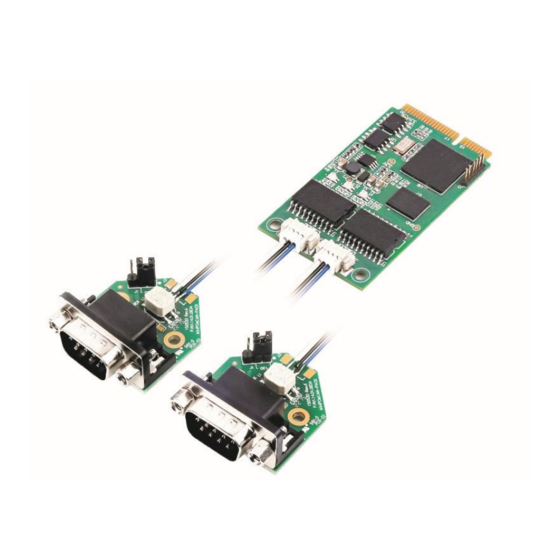
1. Functions MiniPCIeCAN-II is a high-performance MiniPCIe interface CAN card launched by ZLG Electronics, which can connect the CAN network to a computer equipped with a MiniPCIe card slot. MiniPCIeCAN-II adopts the MiniPCIe board in standard dimensions and can be easily installed on laptop or industrial computer with MiniPCIe interface, making it a powerful CAN analyzer. -
Page 5: Functions
Standard MiniPCIe card dimensions: 30 mm (width) x 50.95 mm (length). 1.1 Typical Applications CAN-bus network diagnosis and test; Automotive electronics applications; Electrical communication; Network industrial control equipment; High-speed, large data volume communication. ©2021 Guangzhou ZLG Microelectronics Technology Corp.,Ltd. -
Page 6: Equipment Installation
2. Equipment Installation 2.1 Power Supply MiniPCIeCAN-II uses the MiniPCIe interface 3.3V power supply. The SYS indicator is on, and it turns red first, indicating that the device has power supply. It then flashes a few times and turns green, indicating communication with the PC. -
Page 7: Minipcie Interface Definition
TD1_REV CAN1 TXD second function IO RD1_REV CAN1 RXD second function IO USB_D- USB_D- USB_D+ USB_D+ 3.3V 2, 24, 52 Power supply 9, 15, 18, 21, 26, 27, 29, 34, 35, Ground 40, 50 ©2021 Guangzhou ZLG Microelectronics Technology Corp.,Ltd. -
Page 8: Can Second Function Pin Switch
The following table lists the pin sequence. 错误!未找到引用源。 At this time, R29 and R30 need to weld 0 ohm resistors to enable CAN0, while R31 and R32 respectively weld 0 ohm resistors to enable CAN1. ©2021 Guangzhou ZLG Microelectronics Technology Corp.,Ltd. -
Page 9: Driver Installation
Note: The driver download address is http://www.zlg.cn/canbus/product_detail.php?id=4. B. After the file is copied, connect the MiniPCIeCAN-II intelligent MiniPCIe interface CAN card to the PC correctly; Window will detect the new hardware and automatically start the "Found New Hardware" wizard. Click "Next". See Figure 3.1. -
Page 10: Checking That The Device Is Installed Successfully
Finish installation. See Figure 3.4. Figure 3.4 Driver installation completed F. Click "Finish". MiniPCIeCAN-II Intelligent MiniPCIe interface CAN card initialization indicator SYS is red and off, and the SYS indicator is on in green, indicating that the hardware driver is installed successfully and can be used. -
Page 11: Checking That The New Device Has Been Successfully Installed
Serial Bus Device" device class. After successful installation, you can see the "USBCAN" device under the "Universal Serial Bus Device" device class in the "Device Manager" interface. The following figure shows the normal installation of the "ZLG USBCAN series intelligent CAN interface card" on the computer. See Figure 3.5. -
Page 12: Quick Instructions
4.1.1 Device Type Selection Before operation, select USBCAN2 from the "Select Device" menu, as shown in Figure 4.2. Figure 4.2 Selecting a device The "Open Device" dialog box is displayed, as shown in Figure 4.3. ©2021 Guangzhou ZLG Microelectronics Technology Corp.,Ltd. - Page 13 CAN initialization parameters, click "OK" to open the device operation window (or you can click the "OK and start CAN" button to open the device operation window and automatically start the device and start the CAN channel). ©2021 Guangzhou ZLG Microelectronics Technology Corp.,Ltd.
-
Page 14: Filter Settings
Figure 4.4 Filter Setting 1 The Filter Settings dialog box is displayed, as shown in Figure 4.5. Figure 4.5 Filter Setting 2 Select the filter mode. Set the CAN frame to be filtered by setting the filter. ©2021 Guangzhou ZLG Microelectronics Technology Corp.,Ltd. -
Page 15: Starting The Can
This section describes the simple transmit-receive test, DBC decoding, and bus utilization of MiniPCIeCAN-Ⅱ. 4.2.1 Establishing a Test Environment Ensure that the wiring is correct. Figure 4.8 shows the interface definition, and Figure 4.9 shows the wiring effect. Figure 4.8 Interface definition ©2021 Guangzhou ZLG Microelectronics Technology Corp.,Ltd. - Page 16 In this document, it is built based on our company's core board and backplane. In fact, the driver can be installed as long as the device connected to the MiniPCIe interface is installed. Figure 4.10 and Figure 4.11 show the overall effect. Figure 4.10 Wiring diagram 2 ©2021 Guangzhou ZLG Microelectronics Technology Corp.,Ltd.
-
Page 17: Starting The Device
100K. Since there is no terminal resistor installed for this test, the baud rate should not exceed 100K. If you really use it, you must add a terminal resistor of the corresponding resistance value. ©2021 Guangzhou ZLG Microelectronics Technology Corp.,Ltd. -
Page 18: Sending Data
MiniPCIe Interface CAN Card User Manual User Manual Figure 4.12 No. 1 CAN Figure 4.13 No. 2 CAN 4.2.3 Sending Data When you start the CAN successfully, set the parameters of the CAN frame you want ©2021 Guangzhou ZLG Microelectronics Technology Corp.,Ltd. - Page 19 Figure 4.15. Figure 4.15 Advanced settings for sending data Figure 4.16 and Figure 4.17 show the sending and receiving effect. ©2021 Guangzhou ZLG Microelectronics Technology Corp.,Ltd.
-
Page 20: Real-Time Saving And Stopping Saving
MiniPCIe Interface CAN Card User Manual User Manual Figure 4.16 Sending Figure 4.17 Receiving 4.2.4 Real-time Saving and Stopping Saving When you need to record messages for a long time, use the real-time saving function. ©2021 Guangzhou ZLG Microelectronics Technology Corp.,Ltd. -
Page 21: Dbc Decoding And Display By Id
Click to display the bus utilization interface. The current bus utilization and frame traffic can be monitored in real time. The refresh time can be adjusted to adjust the display speed. See Figure 4.20. ©2021 Guangzhou ZLG Microelectronics Technology Corp.,Ltd. - Page 22 MiniPCIeCAN-II MiniPCIe Interface CAN Card User Manual User Manual Figure 4.20 Bus utilization ©2021 Guangzhou ZLG Microelectronics Technology Corp.,Ltd.
-
Page 23: Error Message Display
When an error occurs in the corresponding CAN circuit, the error message (error sending counter and error receiving counter values), and the time when the error occurred will be printed out. See Figure 4.21. Figure 4.21 Error message ©2021 Guangzhou ZLG Microelectronics Technology Corp.,Ltd. -
Page 24: Method Of Using The Interface Library Functions
Public (optional) Used to declare functions available to all procedures in all modules. Private (optional) Used to declare a function that can only be used in the module that contains the declaration. Name (mandatory) ©2021 Guangzhou ZLG Microelectronics Technology Corp.,Ltd. - Page 25 Indicates that the parameter is passed by value. ByRef (optional) Indicates that the parameter is passed by address. For example: Public Declare Function VCI_OpenDevice Lib "ControlCAN" (ByVal devicetype As Long, ByVal deviceind As Long, ByVal reserved As Long) As Long ©2021 Guangzhou ZLG Microelectronics Technology Corp.,Ltd.
-
Page 26: Interface Library Function Usage Process
MiniPCIeCAN-II MiniPCIe Interface CAN Card User Manual User Manual 5.2 Interface Library Function Usage Process ©2021 Guangzhou ZLG Microelectronics Technology Corp.,Ltd. -
Page 27: Electrical Characteristics
Unless otherwise specified, the parameters listed in Table 6.1 refer to the value at Tamb=25° C. Table 6.1 Electrical characteristics Parameter Name Typical value Remarks Power voltage 3.3V Operating current 200 mA (+3.3V supply voltage) Static level 4 kV (contact)/8 kV (air) Range of temperature -40~+85° C ©2021 Guangzhou ZLG Microelectronics Technology Corp.,Ltd. -
Page 28: Structure And Dimensions
User Manual 7. Structure and Dimensions Board dimensions: 30 mm (width) x 50.95 mm (length) x 7.35 mm (height). Figure 7.1 and Figure 7.2 show detailed dimensions. Unit: mm. Figure 7.1 Main board structure dimensions ©2021 Guangzhou ZLG Microelectronics Technology Corp.,Ltd. - Page 29 MiniPCIeCAN-II MiniPCIe Interface CAN Card User Manual User Manual Figure 7.2 PACK board dimensions ©2021 Guangzhou ZLG Microelectronics Technology Corp.,Ltd.
-
Page 30: Inspection And Maintenance
Under unfavorable environmental conditions, more frequent inspections should be carried out. If you encounter a problem during the maintenance, see Table 8.1 to identify the fault cause. If the fault persists, contact Guangzhou ZLG Electronics Co., Ltd. Table 8.1 Inspection and maintenance Item... - Page 31 Installation Check that No looseness Press the and Wiring each unit is connectors securely together connected completely and and has been lock them with safely locked the slider with the next unit ©2021 Guangzhou ZLG Microelectronics Technology Corp.,Ltd.
- Page 32 Check crimp Leave enough space Visual connectors in between connectors inspection. external Adjust wiring necessary Check No damage Visual damage inspection. external Replace cables cable necessary ©2021 Guangzhou ZLG Microelectronics Technology Corp.,Ltd.
-
Page 33: Disclaimer
ZLG Electronics does not guarantee the applicability of this document at any time. ZLG Electronics shall reserve the right to update this manual without prior notice. To get the latest version, please visit the official website of ZLG Electronics regularly or contact ZLG Electronics. Thank you! -
Page 34: Appendix A Sja1000 Standard Baud Rate
Appendix A SJA1000 standard baud rate Crystal frequency = 16 MHz Baudrate (Kbps) BTR0 (Hex) BTR1 (Hex) 100* 125* 250* 500* 800* 1000* Note: The ones marked with * are the baud rates recommended by the CIA Association. ©2021 Guangzhou ZLG Microelectronics Technology Corp.,Ltd. - Page 35 MiniPCIeCAN-II MiniPCIe Interface CAN Card User Manual User Manual Dreams come true with professionalism and dedication. Guangzhou ZLG more details, Welcome call please visit national service hotline Electronics Co., Ltd. www.zlg.cn 400-888-4005 ©2021 Guangzhou ZLG Microelectronics Technology Corp.,Ltd.
Need help?
Do you have a question about the MiniPCIeCAN-II and is the answer not in the manual?
Questions and answers