Table of Contents
Advertisement
Quick Links
M.2CANFD User Manual
User
Industrial M.2 Interface CAN(FD) Card
2022/5/20
UM01010101 1.2 Date:
Manual
Category
Contents
Keywords
M.2, CAN(FD) interface card
Description
The M.2CANFD is a dual-channel CAN(FD) interface card with
M.2 2280 B-M-Key specification. Backward compatibility with CAN
2.0 A/B standard enables industrial notebook computers/portable
industrial computers/single board computers (SBC) to be
connected to CAN/CAN(FD) networks through M.2 NGFF
interfaces. This constitutes a data acquisition and data processing
system in CAN/CAN(FD) network applications such as
laboratories, industrial control, and smart communities.
©2022 Guangzhou ZLG Electronics Co., Ltd.
Advertisement
Table of Contents

Related Manuals for ZLG M.2CANFD


Summary of Contents for ZLG M.2CANFD
- Page 1 Contents Keywords M.2, CAN(FD) interface card Description The M.2CANFD is a dual-channel CAN(FD) interface card with M.2 2280 B-M-Key specification. Backward compatibility with CAN 2.0 A/B standard enables industrial notebook computers/portable industrial computers/single board computers (SBC) to be connected to CAN/CAN(FD) networks through M.2 NGFF interfaces.
- Page 2 M.2CANFD M.2 Interface CAN (FD) Card User Manual Revision History Version Date Description V1.0 March 18, 2021 Created ©2022 Guangzhou ZLG Electronics Co., Ltd.
-
Page 3: Table Of Contents
3.1 Installing the Driver on Windows ................14 4. Packing List ....................16 5. Quick Instructions ..................17 5.1 Introduction to the ZCANPRO Software............... 17 5.2 M.2CANFD User Guide on ZCANPRO ..............17 6. Disclaimer ....................18 ©2022 Guangzhou ZLG Electronics Co., Ltd. -
Page 4: Functions
M.2CANFD CAN(FD) interface card is a M.2 NGFF to dual-channel CAN(FD) communication interface card compatible with PCI Express r1.0a developed by Guangzhou ZLG Electronics. The M.2CANFD interface card provides the M.2 B+M Key interface, which enables the computer equipped with a M.2 B-key or M-Key slot to be easily connected to the CAN/CAN(FD) bus network and monitor multiple bus networks in real time. -
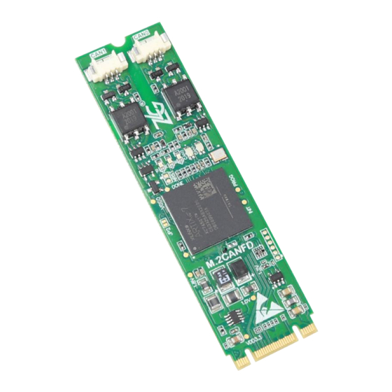
Page 5: Features
M.2CANFD M.2 Interface CAN (FD) Card User Manual Figure 1.1 M.2CANFD product appearance 1.2 Features ⚫ PC interface: standard M.2 B+M Key interface, 2,280 specification, compatible with M-Key and B-Key slots; ⚫ Comply with CAN FD ISO 11898-1:2015 specification (compatible with CAN 2.0A/B standard);... -
Page 6: Specifications
1.3 Specifications 1.3.1 Electrical Parameters The safe and stable operation of the M.2CANFD interface card requires a certain electrical environment. Table 1.1 lists the electrical parameters of the interface card. Exceeding the parameter values listed in the table may cause the product to work unstable and inoperative, or even burn the board. -
Page 7: Specifications
Requirements 1.3.3 Operating Temperature The M.2CANFD interface card can work in an industrial-grade environment. Its applicable operating temperature range: -40°C to +85°C. Using the interface card in too low or too high ambient temperature will make it work abnormally and shorten its service life. -
Page 8: Hardware Interfaces
Network power supply positive 2.3 Terminal Resistance As shown in Figure 2.3, the PACK interface board attached to the M.2CANFD interface card has a built-in 120-ohm terminal resistance. Use the DIP switch S1 to select whether the CAN channel terminal resistance is connected to the bus network. As shown in Figure 2.4, set whether the CAN channel uses the 120 ohm terminal resistance. -
Page 9: Can Second Function Pin Switch
CAN transceiver. When JP2 is short-circuited with solder, the second function pin of CAN signal is automatically enabled when the system is powered on. Table 2.3 lists the pin definitions. Figure 2.2 CAN-TTL switch jumper ©2022 Guangzhou ZLG Electronics Co., Ltd. -
Page 10: Goldfinger Definition
2,4,70,72,74 Power supply 3,27,33,39,45,51,57,71,73 Ground 2.6 Signal Indicators The M.2CANFD interface card has 1 dual-color SYS indicator, 1 dual-color CAN0 indicator, and 1 dual-color CAN1 indicator, which indicate the running status of the device. ©2022 Guangzhou ZLG Electronics Co., Ltd. -
Page 11: Board Installation
CAN1 The CAN interface is faulty After the M.2CANFD interface card is powered on, the system status indicator RUN is green, indicating that the device is powered on, and the system is operating properly; if the system status indicator RUN is off, the system power supply fails or a serious error occurs in the system. - Page 12 2.3 shows the installation procedure: Power off the computer and open the computer case cover; Insert the end of the M.2CANFD series interface card diagonally upward into the free M.2 slot, and then gently press it down; Tighten the screws to fix the board;...
-
Page 13: Product Dimensions
2.7.2 Product Dimensions M.2CANFD complies with the M.2 2280 standard. The width is 22 mm and the length is 80 mm. The height of the highest component on the TOP surface is 3.5 mm, and the height of the highest component on the BOTTOM surface is 1.75 mm. -
Page 14: System Connections
Figure 2.6 Product dimensions 2.8 System Connections When the M.2CANFD interface card is connected to the CAN-bus bus, it is only necessary to connect CAN_L to CAN_L and CAN_H to CAN_H signals. The CAN-bus network adopts a linear topology, and the two terminals of the bus need to be installed with 120 ohm terminal resistors;... - Page 15 M.2CANFD M.2 Interface CAN (FD) Card User Manual Figure 2.8 Double-core single-layer shielded cable connection Figure 2.9 Double-core double-shielded cable connection Figure 2.10 Three-core single-layer shielded cable connection ©2022 Guangzhou ZLG Electronics Co., Ltd.
-
Page 16: Driver Installation
M.2CANFD driver. 3.1 Installing the Driver on Windows First, insert the M.2CANFD interface card into the M.2 card slot of the computer while power off, and start the computer. Click the official driver installation application pcie-canfd-x00u-install.exe to display the driver software interface, as shown in Figure 3.1. - Page 17 M.2CANFD interface card is inserted. At this time, the CANFD card has been connected to the PC, and the host computer software can be used to send and receive CAN (FD) messages.
-
Page 18: Packing List
M.2CANFD M.2 Interface CAN (FD) Card User Manual 4. Packing List Table 4.1 M.2CANFD Packing List V1.00 Name Quantity Unit Remarks M.2CANFD card Piece mPCIeCANFD-PACK interface Piece board Used to connect the 1.25-3P double-headed cable Piece board and the interface board... -
Page 19: Quick Instructions
ZCANPRO software can be downloaded from the ZLG Electronics official website http://www.zlg.cn. 5.2 M.2CANFD User Guide on ZCANPRO After the device driver and ZCANPRO are installed, M.2CANFD can be used on the ZCANPRO software. For details about how to use M.2CANFD on ZCANPRO, click... -
Page 20: Disclaimer
ZLG Electronics does not guarantee the applicability of this document at any time. ZLG Electronics shall reserve the right to update this manual without prior notice. To get the latest version, please visit the official website of ZLG Electronics regularly or contact ZLG Electronics. - Page 21 Dreams come true with professionalism and dedication. Guangzhou ZLG more details, Welcome call please visit national service hotline Electronics Co., Ltd. www.zlg.cn 400-888-4005...
Need help?
Do you have a question about the M.2CANFD and is the answer not in the manual?
Questions and answers