Assa Abloy effeff 1384 Installation And Mounting Instructions
Escape door control terminal
Hide thumbs
Also See for effeff 1384:
- Manual (68 pages) ,
- Fitting and installation instructions (76 pages)
Table of Contents
Advertisement
Advertisement
Table of Contents

Related Manuals for Assa Abloy effeff 1384


Summary of Contents for Assa Abloy effeff 1384
- Page 1 Escape route technology www.assaabloy.com/de Produktname Escape door control terminal Produktname Type 1384/1385 Installations- und Montageanleitung Installation and mounting instructions Experience a safer Experience a safer D0133500 DXXXXXNN and more open world and more open world...
- Page 2 D0133500 04.2022 Copyright © 2022, ASSA ABLOY Sicherheitstechnik GmbH This document and all its parts are copyrighted. Any use or changes outside the strict limits of the copyright are prohibited and liable to prosecution unless prior consent has been obtained from ASSA ABLOY Sicherheitstechnik GmbH .
-
Page 3: Table Of Contents
Table of contents Product information ........6 Escape door control terminal 1384 / 1385 . - Page 4 Operation ..........31 Explanation of symbols .
- Page 5 Step 3: Switch on Menu 9 “Change TSB address”......49 Step 4: Adjust LEDs according to the LED pattern (=address)....50 Step 5: Save LED pattern (= address) .
-
Page 6: Product Information
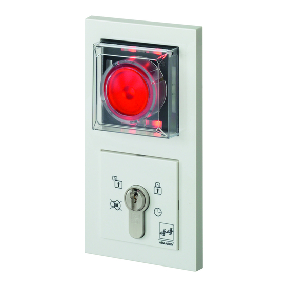
Product information Escape door control terminal 1384 / 1385 The escape door control terminal releases a locked escape door via the emergen- cy button or an external release, such as by a fire alarm system. The permanent release or a temporary release can be activated using the key switch or an external switch, such as a switching timer. - Page 7 Fig. 1: Escape door control terminal Illuminated emergency sign Emergency open button with LED status display The Emergency Open push-button is pressed in the case of an emergency, in order to request a release of the locked escape door. An alarm is also triggered in the process.
-
Page 8: Instructions
Target group The mounting and installation of the product must be carried out by an electri- cian, with expertise in escape-door control systems certified by ASSA ABLOY in accordance with the building authority requirements for electromechanical locking devices for doors in escape routes. The electrician is obliged to apply the recognised rules of technology, inspection directives of the federal states and to update this knowledge on a regular basis. -
Page 9: Safety Instructions
Danger due to faulty commissioning: In order to ensure the safety of the product, commissioning must be performed by a qualified person. ASSA ABLOY Sicherheitstechnik GmbH offers training for qualification in the requisite skills. Danger due to faulty or improperly performed maintenance: The owner is responsible for correct installation and functional inspection of the product and connected components. - Page 10 Risk of death due to electric current: Contact with electricity can cause serious injury or death. The product may only be opened by a qualified electrician with ASSA ABLOY-certified expertise in escape-door controls in accordance with the building authority requirements for electrical locking of doors in escape routes.
-
Page 11: Intended Use
Different uses or combinations of devices not described in the approval are not permitted (“Warranty, disposal”, page 60). ASSA ABLOY Sicherheitstechnik GmbH can provide the necessary planning informa- tion for approved solutions and the device combinations required for your application. The usage must be coordinated with the requirements of the building inspectorate. -
Page 12: Assembly And Connection
Assembly and connection Wall mount The escape door control terminal must be installed in the immediate vicinity of the escape door. It is intended for flush-mounted wall mounting in a commercial- ly available flush-mounted switch box (Fig. 2). Fig. 2 : Flush-mounted switch box Cable selection... - Page 13 Assembly and connection...
-
Page 14: Mounting The Escape Door Control Terminal
Mounting the escape door control terminal 1211 10 9 5 6 7 Fig. 3: Mounting and connecting the escape door control terminal Assembly and connection... - Page 15 Illuminated emergency sign (optional) SYSCON 4 1385EVL4 Escape door module / emergency open button SYSCON 5 1385EVL5 TS Bus Data Universal input Connection of a locking element (see manual D00470xx) Potential-free relay contact 30 V / 1 A – Power supply or via SYSCON4 Jumper, fire alarm system (BMS) ·...
-
Page 16: Replace Profile Half Cylinder (Locking Cylinder)
Replace profile half cylinder (locking cylinder) Disassemble all components until the key switch module is exposed (Fig. 4). Loosen the fastening screw that holds the locking cylinder in place. Pull the profile half cylinder out towards the front. 3.1 Turn the cam upwards (180° position). 3.2 Pull the locking cylinder out towards the front Replace with a suitable new cylinder. - Page 17 Fig. 4 : Replacing the profile half cylinder 180° Assembly and connection...
-
Page 18: Installation And Connection
Installation and connection View of circuit boards Fig. 5 : SYSCON 5 DIP switch View of circuit boards 1211 10 9 SYSCON 4 SYSCON 5 5 6 7 Escape door module Key switch module DIP switch 1 DIP switch 1 is set to OFF at the factory. Tab. -
Page 19: Escape Door Module, Individual, 1384E2N
Escape door module, individual, 1384E2N Fig. 6 : SYSCON 5: SYSCON 4: 5-pin system plug connector for Circuit diagram 4-pin system connectors for connecting the connecting key switch type mains part type 1003FT-24 and/or other 1384E2N 1385ES1/ES3 or other components system components Master-slave configuration (Tab. -
Page 20: Escape Door Module, Single 1385E2N
Escape door module, single 1385E2N Fig. 7 : SYSCON 5: SYSCON 4: Circuit diagram 5-pin system plug connector for 4-pin system connectors for connecting the connecting key switch type mains part type 1003FT-24 and/or other 1385E2N 1385ES1/ES3 or other components system components Master-slave configuration (Tab. -
Page 21: Key Switch Module 1385Es1
Key switch module 1385ES1 Fig. 8 : Individual Max. Circuit diagram 24 V/100 mA 1385ES1 Tampering Tamper SYSCON-5 1385EVL5 Parallel Max. Max. 24 V/100 mA 24 V/100 mA Tampering Tampering Tamper Tamper SYSCON-5 SYSCON-5 1385EVL5 Installation and connection... -
Page 22: Key Switch Module 1385Es2/Es3
Key switch module 1385ES2/ES3 Fig. 9 : Individual Max. Circuit diagram 24 V/100 mA 1385ES2/ES3 Tampering Tamper SYSCON-5 1385EVL5 Parallel Max. Max. 24 V/100 mA 24 V/100 mA Tampering Tampering Tamper Tamper SYSCON-5 SYSCON-5 1385EVL5 Installation and connection... -
Page 23: Key Switch Module 1380E04
Key switch module 1380E04 Fig. 10 : Individual Wiring Diagram 1380E04 Escape door module 1380E04 12 13 14 9 10 SYSCON-5 Parallel 1380E04 1380E04 Escape door module Jumper Remove 10 - 12 10 11 12 13 14 10 11 12 13 14 SYSCON-5 Installation and connection... -
Page 24: I/O Extension Module 901-20
I/O extension module 901-20 Device 1385 can be extended with E/A Extension Module 901-20 to include further switching operations. Potential-free 1 2 3 4 5 6 7 8 0.5AT 0.5AT Relay contact Relay contact Load capability: Load capability: max. 24 V / 2A max. - Page 25 Tab. 2: DIP switch Networked operation Stand-alone operation Configuration using the Address 1385 Set profile (Tab. 3) (DIP 8 = ON) (DIP 8 = Off) Only with Only in master operation of TS bus controller escape door control module 1385 Master-slave configuration (TS-Bus 1385) see Tab.
-
Page 26: Profiles And Pin Assignment Of The I/O Extension 901-20
Profiles and pin assignment of the I/O extension 901–20 Tab. 4: Connec- Description Connec- Description Profil 0 – tions tions Link to higher level Fire detector system Released/locked signal systems (inverse) Burglar alarm system/ Alarm signal (inverse) Interlock Clock Lock Unlock Release with delay Temporary release... - Page 27 Tab. 6: Connec- Description Connec- Description Profile 2 – tions tions Door drive Fire detector system Electric strike/motorised (inverse) lock Burglar alarm system/ Holding magnet interlock Clock Lock Unlock Release with delay Temporary release Tab. 7 : Connec- Description Connec- Description Profile 3 –...
-
Page 28: Wire-Interconnected Interlock (1385)
Wire-interconnected interlock (1385) Note! Escape route securing according to the fail-unlocked principle: If the power fails or is switched off, all doors are unlocked and can be opened at the same time. Function The example describes a basic interlock door system with an emergency exit function without a central bus master (stand-alone operation). -
Page 29: Circuit Diagram Overview
Circuit diagram overview Fig. 12 : Circuit diagram Block door. Central release / central unlocking Installation and connection... -
Page 30: Detailed Circuit Diagram (Example Of Use)
Detailed circuit diagram (example of use) Central locking Central locking Run all I/O modules to a common ground 24 V DC ±10 % Fig. 13 : Circuit diagram in detail Installation and connection... -
Page 31: Operation
Operation Explanation of symbols Fig. 14 : Left buttons Right buttons Symbols Turn the key to the left/right. LED leuchtet LED blinkt Visualization by LEDS. LED ist dunkel Operation... -
Page 32: Temporary Release
Temporary release The locked door can be temporary released for the pre-set duration. · The door can be opened during the temporary release time. · The door can remain open for the duration of the door monitoring interval. · Once the door monitoring interval is exceeded, the pre-alarm is triggered. ·... -
Page 33: Pre-Alarm
Pre-alarm The pre-alarm is a reminder signal. The signal is time limited. The times can be set (“Configure times”, page 42). Prerequisites for a pre-alarm · After a temporary release when the opened door is not closed again within the pre-set temporary release time. ·... -
Page 34: Permanent Release
Permanent release Switch on permanent release Push the key to the left: The four green LEDs light up. The door is permanently unlocked. Locking Pre-conditions for locking: · The door is closed. · No alarm signal is present. Lock The door can be locked. -
Page 35: Alarm Signals
Alarm signals Danger alarm A danger alarm is triggered when: · an emergency button is pressed. · it is activated by a fire alarm system. Danger alarm is reported The door is released immediately. An acoustic danger alarm signal is emitted. -
Page 36: Acknowledging An Alarm
Acknowledging an alarm Acknowledge an alarm and see the cause of the alarm Push the key to the left: The alarm is acknowledged. The four green LEDs flash in pairs. The alarm signal is indicated by an LED sequence pattern (“Technical data, maintenance”, page 57). -
Page 37: Cause Of Alarm
Cause of alarm Displaying cause of alarm An alarm signal is present. Push the key to the left: The alarm is acknowledged. Three green LEDs light up. The lower right-hand green LED flashes. Press and hold the key to the left. ... -
Page 38: Acknowledging An Alarm
Acknowledging an alarm Several alarm statuses can be evaluated and signalled at the same time. The green LEDs continue to flash in pairs in a diagonal sequence if another alarm signal is still present after the alarm has been acknowledged. After all alarm conditions have been reset and the cause of the alarm has been eliminated, the door can be locked. -
Page 39: Configuration
Configuration General The escape door control terminal 1385 can also be configured within a building network using the FT Manager software (manual D01254xx). The escape door control terminal is configured with a key switch via the two switch contacts (turn key switch to the left or key switch to the right). The LEDs visualize the individual configuration modes and settings. -
Page 40: Configuration
Configuration Switch on configuration mode Trigger tamper alarm Unscrew the cover on the escape door module and remove it. The tamper alarm will be triggered. Note! Tamper alarm: The tamper alarm must remain active in order to access configu- ration mode. -
Page 41: Menu On Key Switch
Menu on key switch Menu levels Only one menu level is available (“Menu structure”, page 43). All menu items can be selected with a short left-click from this starting point. There are no other submenus. Advancing through menu items Push the key to the left. ... -
Page 42: Configure Times
Configure times The individual times can be set for the following menus: · Period of time system unlocked · Temporary release time · Pre-alarm time · Alarm time · Duration of the guidance signal. · Activation delay Procedure Turn the key to the right and hold it, hold the key for the desired amount of time. -
Page 43: Menu Structure
Menu structure 1 - Profile 2 - Temporary release time 3 - Door monitoring time 4 - Pre-alarm time 5 - Alarm time 6 - Guidance signal duration 7 - Activation delay ... - Page 44 Tab. 11: Menu items Description Configuration Menu items Starting config- “Configuration”, page 40 uration mode Configuration The yellow mode switched LEDs light Turn 1 – Profile Different pro- Decimal display files (0 to 11) 0 = no LED can be selected 1 = LED1 etc.
- Page 45 Tab. 11: Menu items Description Configuration Menu items 4 - Pre-alarm Duration of Hold time pre-alarm Time freely until the device adjustable. triggers the 1 complete turn alarm. = 1 second (max. 3600 sec.) 5 - Alarm time After the Hold alarm interval Time freely...
- Page 46 Tab. 11: Menu items Description Configuration Menu items 8 – Alarm tones No function assigned: Reserved for extension at a later date 9 – Request The door If the device is ge rt ge rt TSB address control bus online (1385): address is Hold key in requested the...
- Page 47 Tab. 11: Menu items Description Configuration Menu items 11 – Display Binary display of the door control bus address ge rt TSB address Please read the 'Display TSB address, description' section. 32 16 12 – Re-set to The device has Hold key in factory settings been re-set to...
-
Page 48: Configuring The Tsb Address
Configuring the TSB address View TSB Address – Binary Code The TSB address is displayed on request as LED sample binary code: Individual LEDs are assigned binary numbers. To determine the TSB address, the values assigned to the illuminated LEDs must be added. If no LED illuminates, the address is 0. -
Page 49: Step 2: Switch On Configuration Mode
Step 1: Determine the LED pattern of the desired TSB address Each address from 0 to 255 can be displayed with the seven LEDs (“View TSB Address – Binary Code”, page 48). If necessary, mark the desired LED pattern in the illustration for assistance. -
Page 50: Step 4: Adjust Leds According To The Led Pattern (=Address)
Step 4: Adjust LEDs according to the LED pattern (=address). You set each individual address value when the status of the corresponding LED has just changed. The cycle begins again for LED 1 after each selection. You have several attempts to select or deselect the LEDs. -
Page 51: Profile Settings
Profile settings The available profiles are optimised default settings, which you can access. The parameters are adjusted at the factory. These factory settings and the possible adjustment range are shown in the following table. All values in seconds. Tab. 12: Parameters Factory Adjustable... - Page 52 Tab. 13: Profile Description Profiles Input Output External temporary release Combined with a motorized or solenoid lock, or with an electric strike, to release the door in the direction of escape External temporary release To connect to an external locked mode monitoring unit External temporary release To actuate a door drive...
-
Page 53: Master/Slave
Master/Slave In the Master/Slave configuration menu of the escape door terminal 1385, the LEDs show which slaves are online, offline or in address conflict. Display devices on the bus The LEDs 1 to 8 indicate the address ge rt (LED1 = 1, LED2 = 2,...) where a device on the bus has detected the master. -
Page 54: Short Circuit
Short circuit Short circuit is displayed If all eight LEDs (1-8) are flashing, there is ge rt a short circuit in the bus. The system is not ready for operation. Remove the short circuit. Configuration... -
Page 55: Completing A Configuration
Completing a configuration Ending configuration mode Press the key to the left while in configuration mode until the four yellow LEDs flash. Push the key to the right. A long audible signal is emitted. The 4 green LEDs flash in pairs in a diagonal sequence. -
Page 56: Example Configuration
Example configuration The following procedure serves as an example of how you can use the key switch to set and save the pre-alarm time at twenty seconds. Starting configuration mode Open the cover on the escape door module and leave it open. Push the key to the left: Turn the key to the left and hold it for 5 seconds. -
Page 57: Technical Data, Maintenance
Technical data, maintenance Connecting cables Connecting cable Identifier Value Control circuits Length max. 300 m Length of cabling to lock- max. 100 m ing unit TS bus lines (1385) Length max. 1000 m Resistance to bus devices max. 65 Ω Special considerations Use separate line Type... -
Page 58: Escape Door Module
Escape door module Identifier Value Power supply 12 V DC –15% to 24 V DC +15% Controlled direct-current (DC) voltage (SELV) Optimal voltage = 24 VDC Maximum intrinsic current consumption · 12 V DC approx. 150 mA · 24 V DC approx. -
Page 59: Key Switch Module
Identifier Dimension (Centre of mounting screw - cylinder leading edge) DIN profile half cylinder 30.5 mm Lock catch 180° Certification ASSA ABLOY Sicherheitstechnik GmbH Werk Albstadt Sicherheitstechnik GmbH EltVTR Bildstockstraße 20 72458 Albstadt GERMANY The EU declaration of conformity is available in the download area of www.assaabloy.com/de... -
Page 60: Warranty, Disposal
Latest news The latest information is available at: www.assaabloy.com/de Warranty The statutory warranty periods and Terms and Conditions of Sale and Delivery of ASSA ABLOY Sicherheitstechnik GmbH apply. Disposal The following applies to products marked with the symbol (crossed out dustbin): The applicable environmental protection regulations must be observed. -
Page 61: Product
Product WEEE reg. no. DE 69404980 You must dispose of the product correctly as electronic scrap after use and take it to a local collection point for recycling free of charge. You have the following additional options for free disposal through the distribu- tor: ·... - Page 64 Die ASSA ABLOY Gruppe ist der Weltmarktführer Die ASSA ABLOY Gruppe ist der Weltmarktführer in Zugangslösungen. Jeden Tag helfen wir in Zugangslösungen. Jeden Tag helfen wir Menschen sich sicherer und geborgener zu Menschen sich sicherer und geborgener zu fühlen und eine offenere Welt zu erleben.
Need help?
Do you have a question about the effeff 1384 and is the answer not in the manual?
Questions and answers