Assa Abloy 1385 Manual
Escape door control
terminal
Hide thumbs
Also See for 1385:
- Fitting and installation instructions (76 pages) ,
- Installation and mounting instructions (64 pages)

Related Manuals for Assa Abloy 1385


Summary of Contents for Assa Abloy 1385
- Page 1 Escape Door Control Terminal Type 1385/1384 D00558 ASSA ABLOY, the global leader in door opening solutions...
- Page 2 901-20 V. 2.0 and above Copyright: © 2010, ASSA ABLOY Sicherheitstechnik GmbH This document and all its parts are copyrighted. Any use or changes out- side the strict limits of the copyright are prohibited and liable to prosecu- tion if no prior consent is obtained from ASSA ABLOY Sicherheitstechnik GmbH.
-
Page 3: Table Of Contents
........... .13 Individual escape door module 1385 . - Page 4 Set-up operation ........... .28 General .
- Page 5 ...........49 Special function 1385 - networked .
-
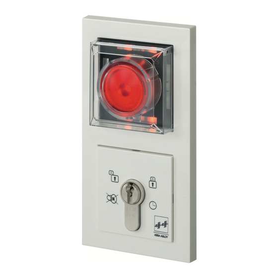
Page 6: Description
• High operational reliability • Less time and effort to install and configure the system • Use of standard switch boxes Functions Overview Networked application 1385 Complex door opening solutions Individual stand-alone system Simplified individual 1384 stand-alone system • Escape door unlocked using integrated emergency button •... - Page 7 • Set-up operation and configuration using a key switch • Cannot be extended Device 1385 (stand-alone function) • Set-up operation and configuration using a key switch • Can be extended with E/A Module 901-20 • Implementation of a wire-interconnected interlock function.
-
Page 8: General
It also provides information regarding how key components work. Note These instructions describe both device types 1384 and 1385 with indi- vidual differing characteristics indicated where required. Symbols The symbols in these operating instructions are designed to help you use in these the devices and instructions quickly and safely. -
Page 9: Packaging And Storage
(1385 only). It is not intended for any other type of use. Note Device 1384 is designed as an offline unit and cannot be extended. Device 1385 can be used as a stand-alone or networked unit. An E/A extension module can be connected in stand-alone mode. Warranty We provide a warranty for this device valid from the date of purchase in accordance with statutory/country-specific regulations. -
Page 10: Installation
Installation Regulations • In accordance with 'Guidelines for electronic locking systems in escape route doors', the escape door control module must be positioned in such a way that the emergency pushbutton is placed between 850 mm and 1200 mm above the finished floor level (FFL). Further regulatory requirements can be found in respective local building ordinances. -
Page 11: Selection Of Cabling
TS bus lines (1385) Description Size Length max. 1,000 m Resistance to bus devices max. -
Page 12: Connecting The Escape Door Module
Connecting the escape door n i t module t i o ( o p f r o 1385EVL5 SYSCON5 locking elements TS-Bus Data 12 - 24 V DC Or via SYSCON4 Universal input +15%; -10% Potential-free relay contact 30 V/1 A See instruction D0047000 Connecting... -
Page 13: Fitting The Escape Door Control Module
Fitting the escape door control module Install all components as indicated in the diagrams. -
Page 14: Replacing The Profile Half Cylinder
Replacing the profile half cylinder Disassemble all components as indicated in the diagrams. Undo the cross-head screw which fastens the profile half cylinder. Take out profile half cylinder through the front and replace with a suitable new cylinder. ... -
Page 15: Installation And Connection
Switch Function Hi-O: Bus termination No function assigned: Hi-O: Group Reserved for extension at a later date Slave Master with TS bus: Master/Slave (1385) (For stand- address 1 * alone operation (For stand-alone without E/A operation with extension E/A extension) -
Page 16: Individual Escape Door Module 1385
Individual Circuit diagram escape door 5-pin connector system for module 1385 connection of the key switch type 1385ES1 or additional components SYSCON-5 Jumper LB1/LB2 Littelfuse 154001 max. 24V / 1A 13 14 15 16 5 6 7 1112 SYSCON-4 2 x 4-pin connector system... -
Page 17: Individual Escape Door Module 1384
Individual Circuit diagram escape door 5-pin connector system for module 1384 connection of the key switch type 1385ES1 or additional components SYSCON-5 Jumper LB1/LB2 Littelfuse 154001 max. 24V / 1A 13 14 5 6 7 15 16 1112 SYSCON-4 2 x 4-pin connector system for connection of the power unit type 1003FT-24-05 and/or... -
Page 18: Individual Key Switch Module
Individual key Circuit diagram switch module Max. 12 V/100 mA Sabotage Tamper SYSCON-5 1385EVL5... -
Page 19: Key Switch Module In Parallel
Key switch Circuit diagram module in parallel Max. Max. 12 V/100 mA 12 V/100 mA Sabotage Sabotage Tamper Tamper SYSCON-5 SYSCON-5 1385EVL5... -
Page 20: Key Switch Module Individual 1380E04
Key switch Circuit diagram module Indi- Indi- Indi- vidual 1380E04 1380E04 Escape door module 9 10 11 12 13 14 3 4 5 SYSCON-5... -
Page 21: Key Switch Module 1380E04 In Parallel
Key switch Circuit diagram module 1380E04 in parallel 1380E04 1380E04 Escape door module Remove Bridge 10 - 12 10 11 12 13 14 10 11 12 13 14 1 2 3 4 5 SYSCON-5... -
Page 22: Locking Elements
Locking For circuit diagrams, see Instructions D0047000. elements Adapter circuit Connection of connecting line SYSCON4 or SYSCON5 to permanent board 1385EAP wiring. Note Do not use SYSCON4 and SYSCON5 together at the same time. An external switch contact (control element) is connected in accordance with the use specifications table. -
Page 23: I/O Extension Module 901-20
I/O Extension Device 1385 can be extended with E/A Extension Module 901-20 to Module include further switching operations. 901-20 Circuit diagram E1-E8 = Inputs/ Signal = Low Active (0V) A1-A4 = Outputs - Open Collector / mass switching (0V) (Note voltage drop!) = Potential-free relay output Load capability max. - Page 24 Profile number Networked operating Stand-alone operating mode mode = on = off The 1385 must be set to Note: A TS bus controller is required. master operation (1385: DIP 3 = on) Note If configuration is carried out using FT Manager, always select Profile '0' (called functions templates in FT Manager) as it is the only place where...
- Page 25 Terminal as- Profile 0 - Link to higher level systems signments Connections Description Connections Description 901-20 Fire detector system Released/locked (inverse) signal Burglar alarm Alarm signal system/Interlock (inverse) Clock Lock Release Release with delay Temporary release Profile 1 - Door drive Connections Description Connections Description Fire detector system...
- Page 26 Profile 2 - Door drive Connections Description Connections Description Fire detector system Electric door strike/ (inverse) Motorized lock Burglar alarm Holding magnet system/Interlock Clock Lock Release Release with delay Temporary release Profile 3 - Interlock Connections Description Connections Description Fire detector system Door is interlocked (inverse) Burglar alarm...
-
Page 27: Wire-Interconnected Interlock (1385)
OPEN switch, locking elements are disengaged and all doors can be opened at the same time. Pre-requirements: • Device 1385 in stand-alone mode (DIP switch 3 = ON) 1 2 3 4 ON • E/A Extension Modules 901-20 with pre-set Profile '3' (also see 'Termi-... -
Page 28: Terminal Assignments 901-20
Circuit diagram overview block door block door block door Emergency opening Terminal assignments 901-20 1 234567 ON 0,5AT 0,5AT green yellow E1 E2 A1 A2 A3 E5 E6 E7 E8 5 6 7 8 9 10 11 12 13 14 15 16 17 18 19 20 21 22 23 24 25 26 2728 Output functions (A1 to A4) - Page 29 Detailed circuit diagram (example of use) Emergency Emergency opening opening Put all I-/O-units to common ground 24 V DC ±10 %...
-
Page 30: Set-Up Operation
Have correct installation and operational capability of the escape door locking device checked by technical specialists. Install 'FT‑Manager' software and check correct functioning (1385 - networked only). Switching on When the system is turned on or there is a failure in the power supply,... -
Page 31: Operation
Operation Explanation of Symbols are used in the following. These mean: symbols Turn the key to the left/right. Indicator display. LED lights up LED flashes LED is dark Temporary- The locked door can be released for the pre-set temporary release time. release •... -
Page 32: Pre-Alarm
Pre-alarm The pre-alarm is a reminder signal. • This signal is time-limited. • Time intervals can be set as required (see 'Change time intervals' section). The reminder signal is an audi- ble intermittent signal. The four green LEDs flash in pairs. -
Page 33: Locking
Locking The door can be locked. Close door if required. Turn the key to the right. The four red LEDs light up. The door is locked. Pre-conditions for locking: The door is closed. No alarm signal is present. Danger alarm The danger alarm is triggered: •... -
Page 34: Tamper Alarm
Tamper alarm The tamper alarm is triggered: • When the emergency button protective cover is opened • By a door contact when a door is forced open • When the cover on the key switch module is removed • When the locking component is tampered with ... -
Page 35: Multiple Alarm
Multiple alarm Several alarm statuses can be evaluated and signalled at the same time. Note The 4 green LEDs continue to flash in pairs in a diagonal sequence if the cause of the alarm is still present after the alarm has been acknowledged. The door can only be locked again when all alarm statuses have been re- set and the causes of the alarm have been remedied. -
Page 36: Configuration
Note A key switch is required to configure devices 1384 and 1385 (stand-alone). You can configure a networked 1385 either with a key switch or by using the FT Manager software within the building network (see separate 'FT Manager' operating instructions). General The escape door control terminal is configured using a key switch, via the two switch contacts in the key switch module. -
Page 37: Starting Configuration Mode
Starting config- Open the protective cover on uration mode the escape door module and leave open. The tamper alarm will be triggered. Note The tamper alarm must remain active in order to access configuration mode. Turn the key to the left ... -
Page 38: Advancing Through Menu Items
Note There is only one menu level. This means all menu items can be selected from here by briefly turning the key to the left to 'start'; there are no submenus. Advancing Turn the key to the left. through menu ... -
Page 39: Menu Structure
Menu structure 1 - Profile 2 - Temporary release time 3 - Door monitoring time 4 - Pre-alarm time 5 - Alarm time 6 - Duration orientation signal 7 - Activation delay ... -
Page 40: Starting Configuration Mode
Menu items Description Configuration Starting config- See 'Starting configuration mode' section uration mode Configuration The yellow mode switched LEDs light up. 1 - Profile Different pro- Turn files (0 to 11) Decimal display 0 = no LED can be selected with specially 1 = LED1 etc. -
Page 41: Pre-Alarm Time
Menu items Description Configuration 4 - Pre-alarm Duration of pre- Hold time alarm until the Time freely device triggers adjustable. the alarm. 1 complete turn = 1 second (max. 255 sec.) 5 - Alarm time After the Hold alarm interval Time freely has elapsed,... -
Page 42: Alarm Tones
(1385). The system then automatically is- The address is requested. sues the next free address (1385). A long audible signal is emitted The device then automatically when the address is identified. changes to the next but one menu item: 'Display TSB address'. -
Page 43: Display Tsb Address
Menu items Description Configuration 11 - Display TSB Binary display of the door control bus address ye rd address Please read the 'Display TSB address, description' section. 32 16 12 - Re-set to The device has Hold key in factory settings been re-set to position for 5... -
Page 44: Ending Configuration Mode
Ending configu- Turn the key to the left while in ration mode configuration mode until the four yellow LEDs flash (11 - End configuration mode). Turn the key to the right. A long audible signal is g g g n emitted. -
Page 45: Automatic Change From Configuration Mode
Automatic If no input is made within one minute while in configuration mode, the change from device automatically switches to operational mode. configuration Several short audible signals are emitted. mode... -
Page 46: Profile Settings
Alarm signal Orientation signal 9999 Activation delay Configuration using FT Manager (1385 - networked) If changes are made, you must always select Profile '0' (called functions templates in FT Manager) as it is the only place where changes can be saved. Note Profile '0' is set by default when the device is delivered. - Page 47 Profile Description Input Output External temporary To connect to a flashing light or an release alarm siren (without time restriction) (inverse) Fire detector system To connect to a flashing light or an (inverse) alarm siren (without time restriction) (inverse) Burglar alarm system To connect to an external locked mode monitoring unit Operated via a...
-
Page 48: Master/Slave
Master/Slave The master/slave configuration menu (1385 only) enables you to use the LED display to identify which slaves are online or offline, or have an address conflict. The LEDs 1 to 8 indicate the ye rd address (LED1 = 1, LED2 = 2,...) - Page 49 You can eliminate address 10 s ye rd conflicts. Turn the key to the left and hold for ten seconds. After five seconds, a bleep will be heard every second. A long acknowledgement signal is emitted after ten seconds.
-
Page 50: Display Tsb Address
Display TSB The TSB address is displayed as a LED sequence in binary form: address Display Individual LEDs are assigned cor- responding binary numbers. An accumulative value between 0 and 255 is indicated depending on which LEDs light up. If no LED lights up, then the binary value is 0. -
Page 51: Example Configuration
Example The following procedure serves as an example of how you can use the key configuration switch to set and save the pre-alarm time at twenty seconds. Starting configuration mode Open the protective cover on the escape door module and leave open. ... -
Page 52: Special Function 1385 - Networked
Special func- Delayed release after EMERGENCY-OPEN is activated tion 1385 - networked Concept If a terminal with an EMERGENCY open element is used instead of an operating unit, it can be used to request the door be unlocked from the main control centre and alarm signals ensure security staff are alerted to control doors. - Page 53 If you don't do this, the door automatically opens after the pre-set delay interval. Schematic diagram Safety-relevant Unlocking RS 232 Bus-Repeater 901-35 Tableau 925 BSM Bus-Repeater 901-35 Tableau 925 BSM Note Security-relevant doors are unlocked on the bus control panel in the permanently manned control centre and not at the door itself.
- Page 54 SYSCON-4 Littelfuse 154001 max. 24V / 1A 13 14 5 6 7 15 16 1112 Kl. 3, 6 To additional 1385 Kl. 4 TS-Bus to Bus-panel Power supply via (permanently occupied Connection of the SYSCON 4 central point) respective locking element See instruction D00470..
- Page 55 Sequence of operation Door secured (exit blocked) EMERGENCY PUSHBUTTON Signal to permanently manned control centre Central FT Manager EMERGENCY-OPEN Delay period 1 FT Manager Delay period 2 Enable door Conditions valid for re-setting? Re-setting...
-
Page 56: Check List - Testing Before Initial Operation
Check list - Testing before initial operation Components Individual components should be checked in a suitable way. Description Does installed locking element comply with guidelines for electronic locking systems in escape route doors? Do controls comply with guidelines for electronic lock- ... -
Page 57: Function
Function Locking Close door Activate locking element. Description Do the four red LEDs light up? Is the door securely locked? (test manually) Temporary release Activate temporary release element. Description The left-hand upper green LED lights up. ... - Page 58 Description Do the four green LEDs light up? Do the four yellow LEDs flash? Close door Re-set alarm. Description Do the four green LEDs light up? Is the door released? (test manually) ...
- Page 59 Description Do the four green LEDs light up? Does the audible alarm signal switch off? Does the emergency key light up? Tamper alarm on the escape door module Activate locking system. Open the protective cover on the escape door module. Description Do the red LEDs light up? ...
- Page 60 Replace the cover onto the key switch module. Description Do the red LEDs light up? Do the yellow LEDs flash? Does the audible alarm signal remain active? Does the door remain locked? (test manually) ...
-
Page 61: Maintenance
Maintenance Annual A technical specialist must: inspection carry out an annual inspection of escape route doors with electric lock- ing systems. issue an inspection certificate, which the building operator must sub- mit to the building inspection authorities if required. Note These instructions are standard specifications. -
Page 62: Alarm Signals
Alarm signals Identification of Alarm signal is present. alarm criteria. Turn the key to the left. g g g n Alarm is acknowledged. The 4 green LEDs flash in pairs g g n n in a diagonal sequence. ... -
Page 63: Identification Of The Cause Of The Alarm
Identification of Alarm signal is present. the cause of the Turn the key to the left. alarm Alarm is acknowledged. Three green LEDs light up. The lower right-hand green LED flashes. Turn the key to the left and hold. -
Page 64: Technical Specifications
Technical Specifications Note The power supply unit must comply with limits established in IEC/EN 60950 with regards to limited capacity power sources. The maximum output rating is limited to 100 W. In the case of power supplies >100 W, a pre-fuse rated at 4 A for 24 V DC or rated at 8 A for 12 V DC should be provided by the customer. -
Page 65: Key Switch Module
Description Value Installation dimensions For standard flush-mounted boxes: 62.5 mm deep Key switch Electrical data module Description Value Contact rating - Max. 12 V/0.1 A (ohmic load) Micro-switch Safety measure Low safety voltage Protection system according to IP30 DIN/EN 60529 Mechanical data Description Value... - Page 68 Produkte und vielseitige Systeme fort sorgen. für den privaten, gewerblichen und öffentlichen Bereich. IKON, hervorgegangen aus der ASSA ABLOY ist der weltweit füh- 1926 gegründeten ZEISS IKON rende Hersteller und Lieferant von AG, ist in Deutschland die erfolg- Schließlösungen und Sicherheits- reichste Marke von ASSA ABLOY für...
Need help?
Do you have a question about the 1385 and is the answer not in the manual?
Questions and answers