
Related Manuals for Assa Abloy effeff 1383


Summary of Contents for Assa Abloy effeff 1383
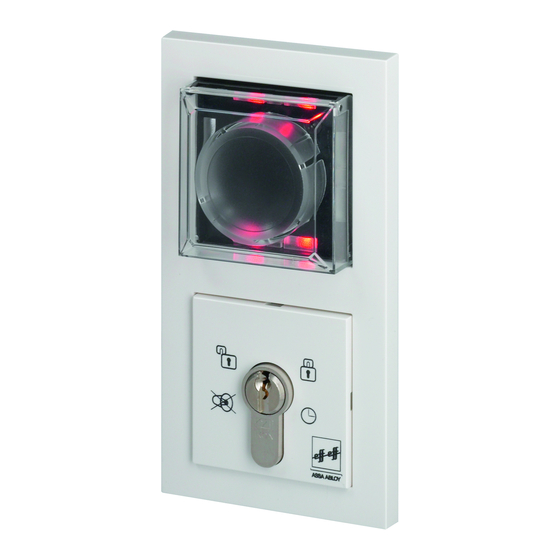
- Page 1 Escape route technology www.assaabloy.de Escape Door Control Terminal Typ 1383/1384/1385/1385T Fitting and Installation Instructions D00558 ASSA ABLOY, the global leader in door opening solutions...
- Page 2 This document and all its parts are copyrighted. Any use or changes outside the strict limits of the copyright are prohibited and liable to prosecution unless prior consent has been obtained from ASSA ABLOY Sicherheitstechnik GmbH. This particularly applies to any copying, translations, microforms, or sto-...
-
Page 3: Table Of Contents
Content Description ............4 General . - Page 4 Set-up operation ........... .32 General .
- Page 5 Automatic change from configuration mode ......47 Change times ............48 Display TSB address .
-
Page 6: Description
Description Innovation In developing the new generation of FT, particular importance was atta- ched to: • Forward-thinking innovation • Versatile range of uses • Operational and functional elements integrated into a compact design • Wide range of functions due to networking of devices •... - Page 7 Device 1383 (RS-485) • For integration into an EAC system via RS-485 interface. • Commissioning and configuration with the integrated key switch. • Cannot be extended Device 1384 (offline version) • A simplified individual stand-alone system not integrated into the building network •...
-
Page 8: General
General Introduction ASSA ABLOY Sicherheitstechnik GmbH‘s extensive experience, and state-of-the-art production and testing procedures ensure the device is highly reliable. These fitting and installation instructions have been compiled for skilled electricians and trained personnel. They are designed to enable you to install and operate the device safely, and fully exploit the permitted range of uses the control terminal has to offer. -
Page 9: Packaging And Storage
Packaging and Our devices are carefully packed to ensure adequate protection during storage shipment. When you receive your device, you must check the device and its packa- ging to ensure that the device is complete and undamaged. Risk of injury The device must not be used if it is damaged. -
Page 10: Installation
Installation Regulations • In accordance with ‚Guidelines for electronic locking systems in escape route doors‘, the escape door control module must be positioned in such a way that the emergency push-button is placed between 850 mm and 1200 mm above the finished floor level (FFL). Further regulatory requirements can be found in respective local building ordinances. -
Page 11: Selection Of Cabling
Selection of Control circuits cabling Identifier Value Length max. 300 m Length of cabling to locking unit max. 100 m Cable cross-section Choose a cable which will ensure the voltage in the locking unit stands at a maximum of 10% under the locking unit's specified rated operating voltage when it is working to full capacity and while... -
Page 12: Connecting The Escape Door Module
Connecting the escape door module l f r t e r t i o ( o p i n s 1385EVL5 SYSCON5 To locking element TS-bus only1385 Data 12 - 24 V DC Or via SYSCON4 Universal input +15%; -10% Potential-free relay contact 30 V/1 A... -
Page 13: Fitting The Escape Door Control Module
Fitting the escape door control module Install all components as indicated in the diagrams. -
Page 14: Replacing The Profile Half Cylinder
Replacing the profile half cylinder Disassemble all components as indicated in the diagrams. Undo the cross-head screw which fastens the profile half cylinder. Take out profile half cylinder through the front and replace with a suitable new cylinder. ... -
Page 15: Installation And Connection
Installation and connection View of circuit SYSCON5 DIP1 boards SYSCON5 1 2 3 4 SYSCON4 5 6 7 Escape door module Key switch module DIP1 All switches set to the OFF position by default in the factory Switch Function Hi-O: Bus No function assigned: termination Reserved for extension at a later date... -
Page 16: Individual Escape Door Module 1385E1N
Individual es- Circuit diagram cape door mo- 5-pin system plug connector for dule 1385E1N connection of the type 1385ES1 key switch or additional components SYSCON-5 Jumpers LB1/LB2 Littelfuse 154001 max. 24V / 1A 13 14 15 16 5 6 7 1112 SYSCON-4 2 x 4-pin system plug... -
Page 17: Individual Escape Door Module 1385E1T
Individual es- The escape door module 1385E1T is designed cape door mo- • for door monitoring with a door contact and dule 1385E1T • as an escape door module with central EMERGENCY OPEN switch. Circuit diagram 5-pin system plug connector for connection of the type 1385ES1 key switch or additional components... -
Page 18: Individual Escape Door Module 1384E1N
Individual es- Circuit diagram cape door mo- 5-pin system plug connector for dule 1384E1N connection of the type 1385ES1 key switch or additional components SYSCON-5 Jumpers LB1/LB2 Littelfuse 154001 max. 24V / 1A 13 14 15 16 5 6 7 1112 SYSCON-4 2 x 4-pin system plug... -
Page 19: Individual Escape Door Module 1383E1N
A different participant address is only necessary in special cases. This can be set manually with the key switch. The procedure is described in the chapter Configuration - Change TSB address. 1383E1N = ASSA ABLOY Interface protocol FT1 1383E2N = ASSA ABLOY Device Protocol AADP... -
Page 20: Key Switch Module 1385Es1 Individuell / In Parallel
Key switch Circuit diagram module Individual Max. 1385ES1 24 V/100 mA Sabotage Tamper SYSCON-5 1385EVL5... - Page 21 Key switch Circuit diagram module 1385ES1 in parallel Max. Max. 24 V/100 mA 24 V/100 mA Sabotage Sabotage Tamper Tamper SYSCON-5 SYSCON-5 1385EVL5...
-
Page 22: Key Switch Module 1385Es2 Individuell / In Parallel
Key switch Circuit diagram module Individual Max. 1385ES2 24 V/100 mA Sabotage Tamper SYSCON-5 1385EVL5... - Page 23 Key switch Circuit diagram module 1385ES2 in parallel Max. Max. 24 V/100 mA 24 V/100 mA Sabotage Sabotage Tamper Tamper SYSCON-5 SYSCON-5 1385EVL5...
-
Page 24: Key Switch Module 1380E04 Individuell / In Parallel
Key switch mo- Circuit diagram dule Individual 1380E04 Escape door 1380E04 module 9 10 11 12 13 14 3 4 5 SYSCON-5... -
Page 25: Locking Elements
Key switch mo- Circuit diagram dule 1380E04 in parallel 1380E04 1380E04 Escape door module Remove jumper 10 - 12 10 11 12 13 14 10 11 12 13 14 1 2 3 4 5 SYSCON-5 Locking For circuit diagrams, see manual D00470. elements... -
Page 26: Adapter Circuit Board 1385Eap
Adapter circuit Connection of connecting line SYSCON4 or SYSCON5 to permanent board 1385EAP wiring. Additional information Do not use SYSCON4 and SYSCON5 together at the same time. An external switch contact (control element) is connected in accordance with the use specifications table. Circuit diagram 5-pin connecting terminal... -
Page 27: I/O Extension Module 901-20
Device 1385 can be extended with E/A Extension Module 901-20 to I/O extension module 901-20 include further switching operations. Circuit diagram E1-E8 = inputs / signal = low active (0V) A1-A4 = outputs - open collector / earth switching (0V) (observe voltage drop!) = potential-free relay output max. - Page 28 Configuration using the 1385 DIP switch networked stand-alone Address Profile number Networked operating Stand-alone operating mode mode = on = off The 1385 must be set to Note: A TS bus controller is required. master operation (1385: DIP 3 = on) Additional information If configuration is carried out using FT Manager, always select Profile ‚0‘...
-
Page 29: Terminal Assignments 901-20
Terminal assign- Profile 0 - Link to higher level systems ments 901-20 Connections Description Connections Description Fire detector system Released/locked (inverse) signal Burglar alarm Alarm signal system/Interlock (inverse) Clock Lock Release Release with delay Temporary release Profile 1 - Door drive Connections Description Connections Description Fire detector system... - Page 30 Profile 2 - Door drive Connections Description Connections Description Fire detector system Electric door strike/ (inverse) Motorized lock Burglar alarm Holding magnet system/Interlock Clock Lock Release Release with delay Temporary release Profile 3 - Interlock Connections Description Connections Description Fire detector system Door is interlocked (inverse) Burglar alarm...
-
Page 31: Wire-Interconnected Interlock (1385)
Wire-intercon- This is a basic interlock door system with an emergency exit function nected inter- without a central bus master (stand-alone). lock (1385) Function As soon as a door is temporarily released or disengaged, the correspondi- ng opposite door (several doors also possible) is blocked and thus cannot be opened. - Page 32 Circuit diagram overview Block door Block door Block door Central unlocking Terminal assignments 901-20 1 234567 ON 0,5AT 0,5AT Green Yellow E1 E2 A1 A2 A3 E5 E6 E7 E8 5 6 7 8 9 10 11 12 13 14 15 16 17 18 19 20 21 22 23 24 25 26 2728 Output functions (A1 to A4)
- Page 33 Detailed circuit diagram (example of use) Central unlocking Central unlocking All I/O modules Connect to common earth 24 V DC ±10 %...
-
Page 34: Set-Up Operation
Set-up operation Additional information The installation and operation of electric locking devices on doors on emergency exit routes are subject to building authority regulations. Com- pliance must be ensured by both the fitter and the building operator. General Before initial commissioning: ... -
Page 35: Operation
Operation Explanation of Symbols are used in the following. These mean: symbols Turn the key to the left/right. Indicator display. LED is lit LED flashes LED is dark Temporary The locked door can be unlocked for the pre-set temporary release time. release •... -
Page 36: Pre-Alarm
Close the door within the pre- set door monitoring interval. The four red LEDs light up. The door is locked. Pre-alarm The pre-alarm is a reminder signal. • This signal is time-limited. • Time intervals can be set as required (see ‚Change time intervals‘ section). -
Page 37: Permanent Release
Permanent The door can be released. release Turn the key to the left. The four green LEDs light up. The door is released. Locking The door can be locked. Close door if required. Turn the key to the right. ... - Page 38 Acknowledging the alarm and main alarm indicator: Turn the key to the left. Alarm is acknowledged. g g g n The 4 green LEDs flash in pairs in a diagonal sequence. g g n n The alarm signal is indicated by an LED sequence pattern (see chapter "Alarm messages").
-
Page 39: Tamper Alarm
Tamper alarm The tamper alarm is triggered: • When the emergency button protective cover is opened • By a door contact when a door is forced open • When the cover on the key switch module is removed • When the locking component is tampered with ... -
Page 40: Multiple Alarm
Multiple alarm Several alarm statuses can be evaluated and signalled at the same time. Additional information The 4 green LEDs continue to flash in pairs in a diagonal sequence if the cause of the alarm is still present after the alarm has been acknowledged. The door can only be locked again when all alarm statuses have been re- set and the causes of the alarm have been remedied. -
Page 41: Configuration
Configuration Additional information A key switch is required to configure devices 1383, 1384 und 1385. You can configure a networked 1385 either with a key switch or by using the FT Manager software within the building network (see separate ‚FT Manager‘ operating instructions). General The escape door control terminal is configured using a key switch, via the two switch contacts in the key switch module. -
Page 42: Switch On Configuration Mode
Open the protective cover on Switch on confi- guration mode the escape door module and leave open. The tamper alarm will be triggered. Additional information The tamper alarm must remain active in order to access configuration mode. Turn the key to the left ... -
Page 43: Advancing Through Menu Items
Additional information There is only one menu level. This means all menu items can be selected from here by briefly turning the key to the left to ‚start‘; there are no submenus. Turn the key to the left. Advancing ... -
Page 44: Menu Structure
Menu structure 1 - Profile 2 - Temporary release time 3 - Door monitoring time 4 - Pre-alarm time 5 - Alarm time 6 - Guidance signal duration 7 - Activation delay ... -
Page 45: Starting Configuration Mode
Menu items Description Configuration Starting confi- See 'Starting configuration mode' section guration mode The yellow Configuration mode switched LEDs light up. Turn 1 - Profile Different profiles (0 to 11) can be Decimal display selected with 0 = no LED specially optimi- 1 = LED1, etc. -
Page 46: Pre-Alarm Time
Menu items Description Configuration Hold 4 - Pre-alarm Duration of pre- time alarm until the Time freely device triggers adjustable. the alarm. 1 complete turn = 1 second (max. 3600 sec.) Hold 5 - Alarm time After the alarm interval has Time freely elapsed, the... -
Page 47: Alarm Tones
Menu items Description Configuration 8 - Alarm tones No function assigned: Reserved for extension at a later date 9 - Request TSB The door con- If the device is ye rd ge rt address trol bus address online (1385): Hold key in is requested the first time the position for 5... -
Page 48: Display Tsb Address
Menu items Description Configuration 11 - Display TSB Binary display of the door control bus address ge rt address Please read the 'Display TSB address, description' section. 32 16 Hold key in 12 - Re-set to The device has factory settings been re-set to position for 5... -
Page 49: Ending Configuration Mode
Turn the key to the left while in Ending configu- ration mode configuration mode until the four yellow LEDs flash (13 - Clo- se configuration mode). Turn the key to the right. A long audible signal is g g g n emitted. -
Page 50: Change Times
Change times The individual times can be set for the following menus: • Period of time system unlocked • Temporary release time • Pre-alarm time • Alarm time • Guidance signal duration • Activation delay Procedure: Turn the key to the right and hold. Hold the key for the desired length of time. -
Page 51: Display Tsb Address
Display TSB The TSB address is displayed on request as LED sample binary code: address Individual LEDs are assigned bina- ry numbers. To determine the TSB address, only the values of the illuminating LEDs have to be added. If no LED illuminates, the address is 0. -
Page 52: Change Tsb Address
Change TSB The adjustment of the TSB address takes place in 6 steps: address Note (1385 only) The link to a connected TSB controller must be disconnected. Additional information The factory setting for the participant address is 1 for escape door modu- le 1383E1N. - Page 53 Step 1 Determine the LED pattern of the desired TSB address Each address from 0 to 255 can be displayed with the 7 LEDs. Mark the LED pattern in the following template as an aid for the adjustment.
- Page 54 Step 2 Switch on configuration mode. Open the protective cover on the escape door module and leave open. The tamper alarm will be triggered. Additional information The tamper alarm must remain active in order to access configuration mode. ...
- Page 55 Step 3 Switch on Menu 9 „Change TSB address“. Turn the key to the left 9 times. ye rd The top yellow LED illuminates the top right red LED blinks. Turn the key to the right and hold for five seconds. ...
- Page 56 Step 4 Adjust LEDs according to the LED pattern (=address). The following applies for each LED: LED is lit: Address value is selected LED is dark: Address value is de-selected You always select or de-select the address value when the status of the corresponding LED changes.
- Page 57 Example Desired address: 11 LED pattern: 1+2+8 Turn the key to the right when: LED 1 illuminates LED 2 illuminates LED 4 goes out LED 8 illuminates LED 16 goes out LED 32 goes out LED 64 goes out...
- Page 58 Step 5 Save LED pattern (=address). If the LED pattern corresponds to the desired address, wait until the pro- cess has cycled through completely. You will hear an audible signal. Briefly turn the key once to the right. ...
-
Page 59: Profile Settings
Profile settings The available profiles are optimised default settings, which you can access. The parameters are adjusted at the factory. These factory settings and the possible adjustment range are shown in the following table. All values in seconds. Parameters Factory Adjustable setting from... - Page 60 Profile Description Input Output External temporary To connect to a flashing light or an release alarm siren (without time restriction) (inverse) Fire detector system To connect to a flashing light or an (inverse) alarm siren (without time restriction) (inverse) Burglar alarm system To connect to an external locked mode monitoring unit Operated via a...
-
Page 61: Master/Slave
Master/Slave The master/slave configuration menu (1385 only) enables you to use the LED display to identify which slaves are online or offline, or have an address conflict. The LEDs 1 to 8 indicate the ge rt address (LED1 = 1, LED2 = 2,...) where a device on the bus has detected the master in the 1385. - Page 62 You can eliminate address 10 s ye rd conflicts. Turn the key to the left and hold for ten seconds. After five seconds, a bleep will be heard every second. A long acknowledgement signal is emitted after ten seconds.
-
Page 63: Display Tsb Address
Display TSB The TSB address is displayed as a LED sequence in binary form: address Display Individual LEDs are assigned corresponding binary numbers. A cumulative value between 0 and 255 is indicated depending on which LEDs light up. If no LED lights up, then the binary value is 0. -
Page 64: Example Configuration
Example The following procedure serves as an example of how you can use the key configuration switch to set and save the pre-alarm time at twenty seconds. Starting configuration mode Open the protective cover on the escape door module and leave open. ... -
Page 65: Check List - Testing Before Initial Operation
Check list - Testing before initial operation Components The individual components should be appropriately checked. Identifier Does installed locking element comply with guidelines for electronic locking systems in escape route doors? Do controls comply with guidelines for electronic locking systems in escape route doors? ... -
Page 66: Function
Function Locking Close door Activate locking element. Identifier Do the four red LEDs light up? Is the door securely locked? (test manually) Temporary release Activate temporary release element. Identifier The left-hand upper green LED lights up. ... - Page 67 Identifier Do the four green LEDs light up? Do the four yellow LEDs flash? Close door Re-set alarm. Identifier Do the four green LEDs light up? Is the door released? (test manually) ...
- Page 68 Identifier Do the four green LEDs light up? Does the audible alarm signal switch off? Does the emergency key light up? Tamper alarm on the escape door module Activate locking system. Open the protective cover on the escape door module. Identifier ...
- Page 69 Replace the cover onto the key switch module. Identifier Do the red LEDs light up? Do the yellow LEDs flash? Does the audible alarm signal remain active? Does the door remain locked? (test manually) ...
-
Page 70: Maintenance
Maintenance Annual A technical specialist must: carry out an annual inspection of escape route doors with electric inspection locking systems. issue an inspection certificate, which the building operator must sub- mit to the building inspection authorities if required. Additional information These instructions are standard specifications. -
Page 71: Alarm Signals
Alarm signals Alarm signal is present. Identification of Turn the key to the left. alarm criteria g g g n Alarm is acknowledged. The 4 green LEDs flash in pairs g g n n in a diagonal sequence. ... -
Page 72: Identification Of The Cause Of The Alarm
Alarm signal is present. Identification of Turn the key to the left. the cause of the Alarm is acknowledged. alarm Three green LEDs light up. The lower right-hand green LED flashes. Turn the key to the left and hold. -
Page 73: Technical Specifications
Technical specifications Additional information The power supply unit must comply with limits established in IEC/EN 60950 with regards to limited capacity power sources. The maximum output rating is limited to 100 W. In the case of power supplies >100 W, a pre-fuse rated at 4 A for 24 V DC or rated at 8 A for 12 V DC should be provided by the customer. -
Page 74: Key Switch Module
Key switch Electrical data module Identifier Value Contact rating - Max. 24 V/0.1 A (ohmic load) Micro-switch Safety measure Low safety voltage Protection system according to DIN/ IP30 EN 60529 Mechanical data Identifier Value Operating temperature range -20°C to +40°C Storage temperature range -20°C to +60°C Installation dimensions... - Page 76 ASSA ABLOY is the global leader in door opening solutions, dedicated to satisfying end-user needs for security, safety and convenience ASSA ABLOY Sicherheitstechnik GmbH Bildstockstraße 20 72458 Albstadt DEUTSCHLAND albstadt @ assaabloy.com Tel. + 497431 123-0 Fax + 497431 123-240...
Need help?
Do you have a question about the effeff 1383 and is the answer not in the manual?
Questions and answers