
Related Manuals for Assa Abloy 1380


Summary of Contents for Assa Abloy 1380
- Page 1 UP-Fluchttürterminal 1380 Installations- und Montageanleitung ASSA ABLOY, the global leader in door D00428 opening solutions...
-
Page 3: Table Of Contents
Inhalt Einführung Anwendung Lieferumfang Bedienung und Anzeigen Anzeigen 6 Bedienung Montageanleitung Übersicht Zylindereinbau Der elektrische Anschluss Nottaster 1380E10 Schlüsselschalter 1380E01/E04 Schlüsselschalter 1380E03/E06 Anschluss Nottaster 1380E10 mit Schlüsselschalter 1380E01/E04 ´ an Fluchttürsteuergerät 720-30/-32 Anschluss Nottaster 1380E10 mit Schlüsselschalter 1380E03/E06 an Fluchttürsteuergerät 720-30/-32 Anschluss Nottaster 1380E10 mit Schlüsselschalter 1380E01/E04 an Fluchttürsteuergerät 720-15 Anschluss Nottaster 1380E10 mit Schlüsselschalter 1380E03/E06... - Page 4 UP-Fluchttürterminal 1380 Seite 4 D00428...
-
Page 5: Einführung
1 . 2 Li e fe rumf ang Der Lieferumfang hängt von der jeweiligen Ausführung ab. Die UP- oder Hohlwand-Schalterdosen gehören nicht zum Lieferumfang. UP-Fluchttürterminal-Set 1380-1X Das Set 1380-1X besteht aus: Schlüsselschalter 1380E0X Nottaster 1380E10 Abdeckrahmen, je nach Schalterprogramm D00428... -
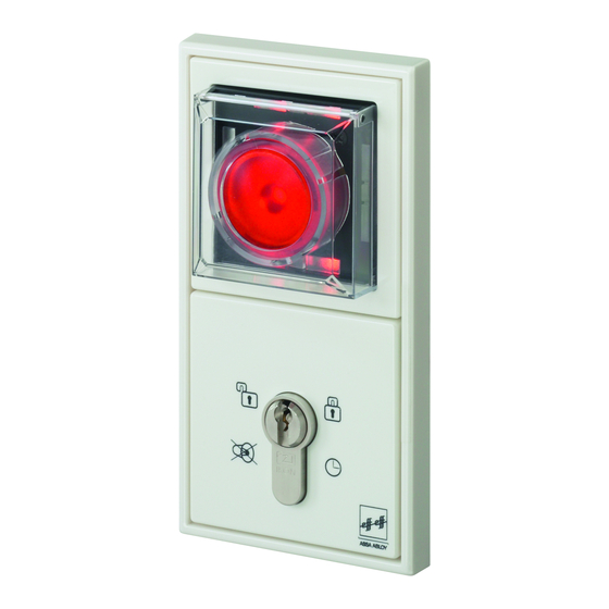
Page 6: Bedienung Und Anzeigen
UP-Fluchttürterminal 1380 Bedienung und Anzeigen Hinweis Die UP-Fluchttürterminals dienen zur Steuerung und Anzeige der Betriebszustände der Fluchttürsysteme. Die Funktion der Fluchttürterminals sowie deren Bedien- und Anzeigeelemente ist abhängig von der Konfiguration und Programmierung des jeweiligen Fluchttürsteuergerätes. Weiterführende Informationen finden Sie in den Anleitungen zu den Fluchttürsteuergeräten. -
Page 7: Bedienung
Bedienung und Anzeigen 2 . 2 Bedienung Das Fluchttürsystem bedienen Sie über den Nottaster und über den Schlüsselschalter. Nottaster Zur Freischaltung des Verriegelungselements im Fluchttürsystem. Drücken Sie auf die rote Betätigungsfläche des Nottasters. Das Verriegelungselement im Fluchttürsystem wird freigeschaltet. Es wird ein Alarm ausgelöst: Die gelben und die grünen Anzeigen leuchten. -
Page 8: Montageanleitung
UP-Fluchttürterminal 1380 Montageanleitung Die Fluchttürterminals 1380XX sind passend für den Einbau in UP- und Hohlwand-Schalterdosen mit einer Einbautiefe von min. 60 mm. 3 . 1 Übersicht Seite 8 D00428... -
Page 9: Zylindereinbau
Montageanleitung 3 . 2 Zylindereinbau 180° D00428 Seite 9... -
Page 10: Der Elektrische Anschluss
UP-Fluchttürterminal 1380 Der elektrische Anschluss 4 . 1 Nottaster 1380E10 4 . 2 Schlüsselschalter 1380E01/E04 10 11 12 14 Sabotage- kontakt Seite 10 D00428... -
Page 11: Schlüsselschalter 1380E03/E06
Der elektrische Anschluss 4 . 3 Schlüsselschalter 1380E03/E06 12 14 Summer D00428 Seite 11... -
Page 12: Anschluss Nottaster 1380E10 Mit Sc Hlüsselschalter 1380E01/E04 An Fluchttürsteuergerät 720-30/-32
UP-Fluchttürterminal 1380 4 . 4 Anschluss Nottaster 1380E10 mit Sc hlüsselschalter 1380E01/E04 an Fluchttürsteuergerät 720-30/-32 Verriegelt Entriegelt Alarm Seite 12 D00428... -
Page 13: Anschluss Nottaster 1380E10 Mit Schlüsselschalter 1380E03/E06 An Fluchttürsteuergerät 720-30/-32
Der elektrische Anschluss 4 . 5 Anschluss Nottaster 1380E10 mit Sc hlüsselschalter 1380E03/E06 an Fluchttürsteuergerät 720-30/-32 Verriegelt Entriegelt Alarm D00428 Seite 13... -
Page 14: Anschluss Nottaster 1380E10 Mit Schlüsselschalter 1380E01/E04 An Fluchttürsteuergerät 720-15
UP-Fluchttürterminal 1380 4 . 6 Anschluss Nottaster 1380E10 mit Sc hlüsselschalter 1380E01/E04 an Fluchttürsteuergerät 720-15 Verriegelt Entriegelt Alarm Seite 14 D00428... -
Page 15: Anschluss Nottaster 1380E10 Mit Schlüsselschalter 1380E03/E06 An Fluchttürsteuergerät 720-15
Der elektrische Anschluss 4 . 7 Anschluss Nottaster 1380E10 mit Sc hlüsselschalter 1380E03/E06 an Fluchttürsteuergerät 720-15 Verriegelt Entriegelt Alarm D00428 Seite 15... -
Page 16: Anschluss Nottaster 1380E10 Mit Schlüsselschalter 1380E01/E04 An Fluchttürterminal 1370-20
UP-Fluchttürterminal 1380 4 . 8 Anschluss Nottaster 1380E10 mit Sc hlüsselschalter 1380E01/E04 an Fluchttürterminal 1370-20 Verriegelt Entriegelt Alarm Seite 16 D00428... -
Page 17: Anschluss Nottaster 1380E10 Mit Schlüsselschalter 1380E03/E06 An Fluchttürterminal 1370-20
Der elektrische Anschluss 4 . 9 Anschluss Nottaster 1380E10 mit Sc hlüsselschalter 1380E03/E06 an Fluchttürterminal 1370-20 Verriegelt Entriegelt Alarm D00428 Seite 17... -
Page 18: Technische Daten
UP-Fluchttürterminal 1380 Technische Daten 5 . 1 Schlüsselschalter 1380E01/E04 Sabotagekontakt 24 V DC/0,5 A max. ohm’sch Last Schaltelement 24 V DC/0,5 A max. (Schlüsselschalter) ohm’sche Last 5 . 2 Schlüsselschalter 1380E03/06 Betriebsnennspannung 12 V bis 24 V DC - 15%, +15%... - Page 19 Technische Daten Für Ihre Notizen: D00428 Seite 19...
- Page 21 Flush-mounted Escape Door Terminal 1380 Installation and Mounting Instructions ASSA ABLOY, the global leader in door D00428 opening solutions...
- Page 23 Contents Introduction Scope of supply Operation and indicator lights Indicator lights Operation Fitting instructions General diagram Cylinder assembly Electrical terminals Emergency button 1380E10 Key switch 1380E01/E04 Key switch 1380E03/E06 Connecting emergency button 1380E10 to key switch 80E01/E04 on escape door control unit 720- 30/-32 Connecting emergency button 1380E10 to key switch 1380E03/E06 on escape door control unit 720-30/-32 Connecting emergency button 1380E10 to key switch 1380E01/E04...
- Page 24 Flush-Mounted Escape Door Terminal 1380 Page 24 D00428...
-
Page 25: Introduction
1 . 2 Scope of supply The scope of supply depends on the individual system design. Flush-mounted or wall cavity switch boxes are not included in the supplied package. Flush-mounted escape door terminal set 1380-1X Set 1380-1X consists of: Key switch 1380E0X... -
Page 26: Operation And Indicator Lights
Flush-Mounted Escape Door Terminal 1380 Operation and indicator light s Note The flush-mounted escape door terminals are used to control and indicate the escape door system operating status. Escape door terminal operation and its operational and indicator elements are dependent on the configuration and programming in the respective escape door control unit. -
Page 27: Operation
Operation and indicator lights 2 . 2 O p e r a ti o n You can operate the escape door system using the emergency button or the key switch. Emergency button For releasing the locking element in the escape door system. Press the red area to activate the emergency button. -
Page 28: Fitting Instructions
Flush-Mounted Escape Door Terminal 1380 Fit ting instructions Escape door terminals1380XX can be fitted into flush-mounted and wall cavity switch boxes with a minimum mounting depth of 60 mm. 3 . 1 G e n e r al d i a gr a m... -
Page 29: Cylinder Assembly
Fitting instructions 3 . 2 Cylinder assembly 180° D00428 Page 29... -
Page 30: Electrical Terminals
Flush-Mounted Escape Door Terminal 1380 Electrical terminals 4 . 1 Emergency button 1380E10 4 . 2 Key switch 1380E01/E04 10 11 12 14 Tamper contact Page 30 D00428... -
Page 31: Key Switch 1380E03/E06
Electrical terminals 4 . 3 Key switch 1380E03/E06 12 14 Buzzer D00428 Page 31... -
Page 32: Connecting Emergency Button 1380E10 To Key Switch 80E01/E04
Flush-Mounted Escape Door Terminal 1380 4 . 4 C o n n e c t i ng e m e rg e n c y b u t t o n 1 3 8 0 E 1 0 t o k e y s w i t c h 8 0 E 0 1 / E 0 4 o n... -
Page 33: On Escape Door Control Unit 720
Electrical terminals 4 . 5 Connecting emergency button 1380E 10 to key switch 1380E03/E06 on escape door control unit 720-30/-32 Locked Unlocked Alarm D00428 Page 33... -
Page 34: Connecting Emergency Button 1380E10 To Key Switch 1380E01/E04 On Escape Door Control Unit 720-15
Flush-Mounted Escape Door Terminal 1380 4.6 Connecting emergency button 1380E10 to key switch 1380E01/E04 on escape door control unit 720-15 Locked Unlocked Alarm Page 34 D00428... - Page 35 Electrical terminals 4.7 Connecting emergency button 1380E10 to key switch 1380E03/E06 on escap e d o or c o nt r ol u n i t 7 20 - 1 5 Locked Unlocked Alarm D00428 Page 35...
-
Page 36: Connecting Emergency Button 1380E10 To Key Switch 1380E01/E04
Flush-Mounted Escape Door Terminal 1380 4.8 Connecting emergency button 1380E10 to key switch 1380E01/E04 on escap e d o or c o nt r ol u n i t 1 37 0 - 2 0 Locked Unlocked Alarm Page 36... -
Page 37: Connecting Emergency Button 1380E10 To Key Switch 1380E03/E06
Electrical terminals 4.9 Connecting emergency button 1380E10 to key switch 1380E03/E06 on escap e d o or c o nt r ol u n i t 1 37 0 - 2 0 Locked Unlocked Alarm D00428 Page 37... -
Page 38: Specifications
Flush-Mounted Escape Door Terminal 1380 Specifications 5 . 1 Key switch 1380E01/E04 Tampering contact 24 V DC/0.5 A max. ohmic resistance Switch unit(key switch) 24 V DC/0.5 A max. ohmic resistance 5 . 2 Key switch 1380E03/06 Rated operating voltage... - Page 40 ASSA ABLOY ist der weltweit führende Hersteller ZEISS IKON AG, ist in Deutschland die erfolgreichste und Lieferant von Schließlösungen und Sicherheits- Marke von ASSA ABLOY für Schließ- und Sicherheits- systemen, die den hohen Ansprüchen der Kunden technik. Produkte und Lösungen der Marke IKON...
Need help?
Do you have a question about the 1380 and is the answer not in the manual?
Questions and answers