Chamberlain 3000 Series Owner's Manual
Hide thumbs
Also See for 3000 Series:
- Owner's manual (40 pages) ,
- Installation instructions manual (28 pages) ,
- Owner's manual (20 pages)
Table of Contents
Advertisement
Quick Links
Serial #
(located on electrical box cover)
Installation Date
Wiring Type
OWNER'S MANUAL
SERIES 3000
MODEL GJ
INDUSTRIAL DUTY
GEARHEAD JACKSHAFT OPERATOR
©
COMMERCIAL DOOR OPERATOR
LISTED
®
®
NOT FOR RESIDENTIAL USE
The Chamberlain Group, Inc.
A DUCHOSSOIS ENTERPRISE
845 Larch Avenue
Elmhurst, Illinois 60126
Advertisement
Table of Contents

Related Manuals for Chamberlain 3000 Series


Summary of Contents for Chamberlain 3000 Series
- Page 1 The Chamberlain Group, Inc. A DUCHOSSOIS ENTERPRISE 845 Larch Avenue © Elmhurst, Illinois 60126 OWNER'S MANUAL SERIES 3000 MODEL GJ INDUSTRIAL DUTY GEARHEAD JACKSHAFT OPERATOR Serial # (located on electrical box cover) COMMERCIAL DOOR OPERATOR Installation Date LISTED ® Wiring Type ®...
-
Page 2: Specifications
SPECIFICATIONS MOTOR ELECTRICAL TYPE: ........Continuous Duty TRANSFORMER: ...24VAC HORSEPOWER: ....1/3, 1/2, 3/4 & 1 Hp CONTROL STATION:..3 Button Single or Three Phase OPEN/CLOSE/STOP, NEMA 1 1-1/2 & 2 HP Three Phase WIRING TYPE: ....B2 (Standard) SPEED: ......1725 RPM Momentary Contact to OPEN/CLOSE/STOP plus Wiring for Sensing Device to Reverse and Auxiliary VOLTAGE: ......115/230 Single Phase Devices to Open and Close with Open Override (Other... - Page 3 INSTALL OPERATOR WARNING CAUTION TO AVOID DAMAGE TO DOOR AND OPERATOR, KEEP DOOR BALANCED. STICKING OR BINDING MAKE ALL DOOR LOCKS INOPERATIVE. SECURE DOORS MUST BE REPAIRED. DOORS, DOOR LOCK(S) IN "OPEN" POSITION. SPRINGS, CABLES, PULLEYS, BRACKETS AND THEIR HARDWARE MAY BE UNDER EXTREME IF THE DOOR LOCK NEEDS TO REMAIN TENSION AND CAN CAUSE SERIOUS PERSONAL FUNCTIONAL, INSTALL AN INTERLOCK SWITCH.
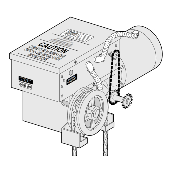
- Page 4 4. Place drive sprocket on the appropriate side of FIGURE 4 the operator. Do not insert the key at this time. 5. Join roller chain ends together with master link. 6. Raise operator to approximate mounting position and position chain over door and operator sprockets.
- Page 5 OPTIONAL FEATURES AVAILABLE Installation of Operator REEL (OPTIONAL) to Sectional Door (Metal Building) Take-up reel should be installed 12" above the top of the door. COIL CORD (OPTIONAL) Wire (24V) Connect operator end of coil cord to junction box (not supplied) fastened to the wall approximately halfway up the door opening.
- Page 6 ADJUST LIMITS WARNING TO AVOID SERIOUS PERSONAL INJURY OR DEATH FROM ELECTROCUTION, DISCONNECT ELECTRIC POWER BEFORE MANUALLY MOVING LIMIT NUTS. MAKE SURE THE LIMIT NUTS ARE POSITIONED BETWEEN THE LIMIT SWITCH ACTUATORS BEFORE PROCEEDING WITH ADJUSTMENTS. 1. Depress open limit switch. The operator should stop. 2.
-
Page 7: Maintenance Schedule
ADJUST CLUTCH (OPTIONAL) WARNING Motor Clutch TO AVOID SERIOUS PERSONAL INJURY OR DEATH FROM ELECTROCUTION, DISCONNECT ELECTRIC POWER TO OPERATOR BEFORE ADJUSTING SLIP Adjusting CLUTCH. Remove clutch cover and adjust clutch so that it is tight enough to open and close the door but will slip when the door meets an obstruction. -
Page 8: Adjust The Brake
SPANS AMERICA INSTALLATION AND SERVICE INFORMATION ADDRESS ORDER TO: ARE AVAILABLE 6 DAYS A WEEK THE CHAMBERLAIN GROUP, INC. CALL OUR TOLL FREE NUMBER - 1-800-528-6563 Electronic Parts & Service Dept. HOURS 7:00 TO 3:30 p.m. (Mountain Std. Time) 2301 N. Forbes Blvd., Suite 104... - Page 9 MEMO:...
- Page 10 SINGLE PHASE WIRING DIAGRAM SINGLE PHASE WIRING DIAGRAM (For PC Board #14D0379) (For P.C. Board #14D0379) The Chamberlain Group, Inc. Brown Wiring Diagram Standard Duty 1Ø SENSING AUXILARY LIMIT DEVICE LIMIT (Reference Label 132B2041B) SWITCH SWITCH 4/28/91 - 6/1/91 - 6/11/91 - 6/15/91...
- Page 11 SINGLE PHASE SCHEMATIC DIAGRAM SINGLE PHASE SCHEMATIC DIAGRAM (For P.C. Board #14D0379) (For P.C. Board #14D0379) Neutral 115v 1Ø Hot 115v 1Ø White Black Single Phase Overload Protector Orange Yellow 115 Vac Only Orange P1-4 P1-1 MOTOR Blue Brake (If Req'd) Black Orange * NOTE: Remove Jumper...
- Page 12 THREE PHASE WIRING DIAGRAM (For P.C. Board #14D3079) THREE PHASE WIRING DIAGRAM (For PC Board #14D0379) Brown AUXILARY SENSING LIMIT DEVICE LIMIT SWITCH SWITCH OPEN CLOSE LIMIT LIMIT SWITCH SWITCH Yellow Gray Gray Blue Blue Orange Brown Brown Brown Orange Blue Orange Blue...
- Page 13 THREE PHASE SCHEMATIC DIAGRAM (For P.C. Board #14D0379) Hot 3Ø Hot 3Ø Hot 3Ø White Orange Three Phase Overload Relay (3/4 HP to 2 HP Only) Orange Yellow Orange P1-4 P1-1 MOTOR Brake Blue Req'd) Black Orange Place Jumper Between 3 & 4 If 3Ø...
- Page 14 WIRING KITS TYPE STATION B2, C2, D1, E2, T D1, E2 3 Button Function: Momentary contact to open, close and stop, plus wiring for sensing device to reverse and auxiliary devices to open and close with open override. B2, T, B2, C2, E2 T, TS B2, C2,...
- Page 15 NEMA MOTOR WIRING DIAGRAMS he Chamberlain Group, Inc. NEMA Motor Wiring Diagrams NEMA MOTOR WIRING DIAGRAMS /1/92 SINGLE VOLTAGE 1 PHASE 1/3 & 1/2 H.P. 115 V only 115V 115V 230V Motor Motor Motor T2 White Black T1 - Blue...
- Page 16 ILLUSTRATED PARTS – ELECTRICAL BOX SERIES...
-
Page 17: Electrical Box
REPAIR PARTS – ITEM PART NO. DESCRIPTION ELECTRICAL BOX 1B3727 Terminal Assy. 3-Lug 41K4304 Switch Bracket Assy. (Aux. & Sensing) SERIES 1B3796 Ltd. Shaft-Sprocket Assy. 1B3938 Cover & Hinge Assy. 1C3937 Electric Box Assy. 1D4017 Wire Harness 11A012 Flanged Sleeve Bearing 41K4303 Limit Bracket (Adj.) Kit 1B4080... - Page 18 ILLUSTRATED PARTS – OPERATOR MODEL See Illustration A - Page 8...
-
Page 19: Repair Parts
REPAIR PARTS – ITEM PT. NO. DESCRIPTION QTY. See Chart Motor MODEL 80D8 Gear Reducer, 1-1/2 & 2 HP 80D9 Gear Reducer up to 1 HP See Detail Electric Box, Basic w/P.C.B 1D4098 Frame Assembly, GJ Brake/Hoist 31C373 Cover, GJ Brake Housing 1B4421 Brake Shoe/Lining Assembly 81B127... -
Page 20: Control Connection Diagram
TIMER DEFEAT SWITCH REMOVE JUMPER TIMER 2 OR MORE WIRING TYPES - B2, C2, D1, E2, T & TS WIRING TYPES - ALL WIRING TYPES - T & TS © 1992, The Chamberlain Group, Inc. 114A1669A All Rights Reserved Printed in Mexico...