Advertisement
Quick Links
Advertisement
Chapters

Related Manuals for Eaton ARRAY 3A3 Pro


Summary of Contents for Eaton ARRAY 3A3 Pro
- Page 1 ARRAY 系列 3A3 Pro UPS 使用手册...
- Page 3 感谢您使用本公司产品! 请严格遵守本手册中和机器上的所有警告及操作说明并妥善保管 本手册。在没有阅读完所有的安全说明和操作说明以前,请不要 操作 UPS。...
- Page 4 严 正 声 明 监管码声明 为了切实保障您的消费权益和用电安全,请注意以下事项: 1 、每一台 ARRAY 3A3 Pro 机身上均贴有“电子监管码”(“电子监管码”是国家质检总 局为打击假货推行的一种产品身份识别码 )。 2 、消费者可以通过以下途径对产品电子监管码进行查验,并可通过“中国产品质量电子监 管网”平台进行投诉、举报。 查询方式: 网站查询:登陆 www.95001111.com (中国产品质量电子监管网),输入监管码进行查询; 电话查询: 95001111 进行查询(未开通地区可拨打 010-95001111 ); 短信查询:将监管码发送至 106695001111 (移动、联通均可); 如有疑问,可以拨打电话 95001111 或登陆 www.95001111.com 点击“消费者通道”进行举 报投诉。 版权声明 本公司致力于技术创新,不断提供更好的产品和服务满足客户需求,对产品设计、技术规 格的更新,恕不另行通知。产品以实物为准。 请登陆网站 www.eaton.com/powerquality 下载最新版的产品说明书。...
- Page 5 9. 使用脚轮运输机柜时,请事先将机柜内的所有 U P S 模块拉出,插入 U P S 模块时必须使用 调平底座承重 ( 请勿使用脚轮承重 )。 电气安全 1. 上电前,请确认已正确接地,并检查接线和电池极性的连接正确。 2. 当 U P S 需要移动或重新接线时,应将交流输入电源断开,并保证完全 U P S 停机,否则输 出端仍可能带电,有触电的危险。 3. 请使用 Eaton 指定的附加装置和附件。 电池安全 1. 电池的寿命随环境温度的升高而缩短。定期更换电池可保证 U P S 工作正常,并保证足够 的后备时间。 2. 蓄电池维护只能由具备蓄电池专业知识的人员来进行。 3. 更换蓄电池,必须使用相同类型和型号的蓄电池,且数量必须相同。...
- Page 6 使用保养 1. 使用环境及保存方法对本产品的使用寿命及可靠性有一定影响,因此,请注意避免在下 列工作环境中使用: a. 超出技术指标规定(温度 0-40 ℃,相对湿度 20-90% )的高、低温和潮湿场所; b. 有振动、易受撞的场所; c. 有金属性粉尘、腐蚀性物质、盐份和可燃性气体的场所。 2. 如果长时间放置不使用,必须将 UPS (不带电池)存放在干燥的环境中,存贮温度范围 : - 25 - 55 ℃。 UPS 开机之前,必须先让环境温度回暖至 0 ℃以上,并维持一段时间。...
-
Page 7: Table Of Contents
目 录 第一章 简介 ------------------------------------------------------- 第二章 包装拆卸说明 ----------------------------------------------- 第三章 UPS 外观图 ------------------------------------------------ 第四章 UPS 安装 -------------------------------------------------- 第五章 电气安装 --------------------------------------------------- 第六章 在线增减、更换 UPS 模块 ------------------------------------ 第七章 运行操作 --------------------------------------------------- 第八章 菜单命令 --------------------------------------------------- 第九章 UPS 维护 --------------------------------------------------- 第十章 通讯界面 --------------------------------------------------- 第十一章 常见问题处理 --------------------------------------------- 第十二章... -
Page 8: 第一章 简介
第一章 简介 1.1 常用符号说明 1.2 手册适用对象 本手册只适用于 ARRAY UPS 系列的 3A3 Pro UPS 。 1.3 产品简介 3A3 Pro UPS 属于 ARRAY UPS 系列,是高效率、高性能的双转换纯在线式 UPS 产品。与其它 AR- RAY UPS 系列产品一样,采用抽屉式高智能模块化设计,一个 UPS 模块就是一台功能齐全的三进三 出的 UPS 。用户可以通过增减机内 UPS 模块来满足功率输出及可靠性要求,达到最佳性价比。 3A3 Pro UPS 由 UPS 机柜、 UPS 模块、 配电盘 ( 选配件 )、 防尘模块 ( 选配件 )、 防雷模块 ( 选配件 ) 组成。 UPS 系统采用的是标准... - Page 9 3A3 Pro UPS 可以解决几乎所有的电力问题,如电涌、高压突波、暂态过电压、电压下陷、噪声干扰、 频率漂移、谐波、电压过低、市电中断等。 本系列产品产品适用范围广泛,从计算机设备到通信系 统以及自动设备都可以使用。 1.4 产品标准 3A3 Pro UPS 产品符合下列等级标准 EMC: IEC 62040 2 2005 C3 警告:如本产品用于 C2 环境中,应采取附加措施进一步抑制电磁干扰。 安规: GB 4943.1-20 11 信息技术设备安全第 1 部分:通用要求 YD/T 1095-2008 通信用不间断电源 -UPS 1.5 热线电话 如果您有任何问题,请拨打 EATON 的服务热线电 400-889-3938,我公司客服人员将为您提供 24 小 时不间断的服务响应。...
-
Page 10: 第二章 包装拆卸说明
第二章 包装拆卸说明 2.1 机柜拆卸说明 注意:请检查包装是否在运输过程中损坏,如发现损坏请勿继续操作,请通知承运商与经销商。检查 随机附件:使用手册一本 , 螺丝与绑线附件一份,机柜钥匙两把。 1. 拆顶盖,用剪刀剪断打包带,取下顶盖(图 2-1 )。 2. 拆侧板,用老虎钳将侧板的插舌掰直,取下四周侧板(图 2-2 )。 3. 移走箱体上方及四周的填充物及胶袋(图 2-3 )。 4. 用扳手卸下机柜底部固定支脚的螺丝并调节固定支脚的高度(图 2-4 )。 5. 利用包材斜坡板,前后至少各一人协作将箱体小心推至地面(图 2-5)。 注意:搬运之前先确认门及通道内其他障碍物的高度。 图 2-1 图 2-2 图 2-3 图 2-5 图 2-4... - Page 11 2.2 模块包装拆卸说明 1. 切断包装带,打开纸箱(图 2-6 ); 2. 向上移走 UPS 模块上方填充物(图 2-7 ); 3. 取出 UPS 模块(图 2-8 ); 注意: UPS 模块较重,需要两人搬运操作。 图 2-6 图 2-7 图 2-8...
-
Page 12: 第三章 Ups 外观图
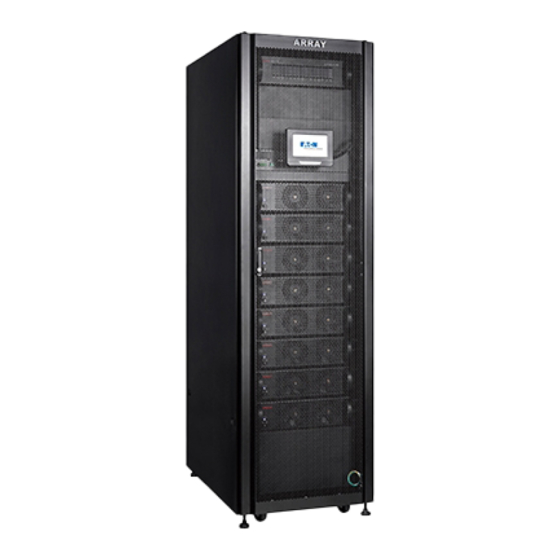
第三章 UPS 外观图 3.1 UPS 机柜外观图 配电盘 ( 选配 ) LCD 面板 通讯接口 UPS 模块 150kVA 120kVA 图 3-1 前视图 图 3-2 上出线机柜顶视图(右图含束线架 ) - Page 13 图 3-3 120K 上出线机柜后视图 图 3-4 120K 下出线机柜后视图 图 3-5 150K 后视图 图 3-6 150K 下出线机柜后视图...
- Page 14 3.2 UPS 模块外观图 指示灯 定位锁 图 3-7 模块前视图 图 3-8 模块后视图 图 3-9 模块顶视图 图 3-10 配电盘模块模块前视图...
-
Page 15: 第四章 Ups 安装
第四章 UPS 安装 4.1 安装需知 1. 请在干净、平稳的环境中安装 UPS ,避开震动、灰尘、高湿、可燃性气体、可燃性液体或腐蚀性 物质环境。 2 . UPS 正常工作时的环境温度要求在 0 - 40 ℃之间。如果工作在 40 ℃以上的环境里,要求最大带载量 按每增加 5 ℃,递减 12 % 额定值实施。 UPS 工作时的最高环境温度要求不超过 50 ℃。 3. 电池组建议在 15 - 25 ℃之间使用。 4. UPS 满载正常运行时的海拔高度不应高于 1000 米,如果在高海拔地区使用 UPS ,请降额使用。各 海拔高度正常运行对应的降额系数如下表所列:... - Page 16 图 4-1 4.3 安装步骤 1. 用套筒或扳手卸下栈板上的木螺丝,取下机柜固定支架并调节调平底座高度。 2. 将机柜推到预定位置后并用扳手调节调平底座至脚轮悬空。 3. 用固定支架固定调平支脚(使用 M8 地脚螺丝)(如图 4-2 )。 图 4-2 4. 拆掉 UPS 模块的包装,检查模块前面板上的定位锁的状态,正常情况定位锁上的白点应该对准 “ ”位置(图 4-3 );如果白点对准“ ”位置,请用手拧到“ ”位置。 图 4-3...
- Page 17 5. 将 UPS 模块装入到机柜的模块插槽内,沿着插槽将模块平推到机柜内直到模块完全插入到机柜内。 注意:模块较重,安装时需要两个人一起进行。 6. 将模块前面板的定位锁打到“ ”位置(图 4-4 ); 7. 重复上述 4-6 的步骤将所需 UPS 模块依次全部安装到 UPS 机柜内(图 4-5 ); 8. 安装配电盘模块(选配): 卸下配电盘安装位置的盲板,调整活动螺母的位置和配电盘的安装孔保 持一致 , 将配电盘使用 M6 内六角螺丝固定到预定位置(图 4-5 ); 9. 配电盘接线:将配电盘后方的电缆按标识连接到 UPS 输出铜条的对应位置。 注意: 配电盘高度为 3U,2 个安装孔之间的距离 2U; 配电盘的安装位置和进出线位置保持一致 ( 机柜上进出线时配电盘置于机柜上方前侧,下进出线时置 于机柜下方前侧...
-
Page 18: 第五章 电气安装
第五章 电气安装 3A3 Pro UPS 电气部分的安装必须由经过培训的合格工程师依据 “电工法则” 与 “ 3A3 Pro UPS 安装规范” 进行,严禁其它人员违规进行安装,本手册只介绍安装的基本内容,具体安装细节请参考安装规范。 5.1 电力线选择 3A3 Pro UPS 机柜容量 (可以容纳的 UPS 模块数) 有四种可以选择, 60kVA (最多容纳四个 UPS 模块) 、 90kVA (最多容纳六个 UPS 模块)、 120kVA (最多容纳八个 UPS 模块)、 150kVA (最多容纳十个 UPS 模块),电力线线径的选择应该在此基础上再考虑过载以及电网电压的因素进行,一般情况下建 议用户按照机柜的最大容量选择电力线,以保证... - Page 19 5.2 开关及保护元件选择 3A3 Pro UPS 机柜中自带开关, 3A3 Pro UPS 机柜中输出只接有开关,不带保护元件。用户在安装 3A3 Pro UPS 时需要在 UPS 输入与输出外接开关及保护元件,建议选用“无熔丝断路器( NFB )”代 替传统的开关与保险丝组合件。 NFB 的选择需同时考虑电压规格与电流规格, 用户可以根据负载情况进行选择, 因为 NFB 是保护元件, 建议按 UPS 的实际容量进行选择,否则起不到应有的保护作用。本手册根据 UPS 模块的数量列出了 NFB 的需求情况,供用户在安装时参考 ( 详情见下表 )。 UPS 输入 NFB UPS 输出 NFB 电池...
- Page 20 说明: 1 . UPS 输入 N 线必须正确连接。 2 . 3A3 Pro UPS 一组电池为 32- 40 节电池串联 , 以 40 节电池为例进行说明,中间(第二十节电池与 第二十一节电池相联处)引出一条中线,加上首、尾的引出线一共有 3 条线与 UPS 接线排相连。电 池线引出必须经过一个直流断路器才能接到 UPS 对应的接线排上,具体接线请参考下图: 图 5-2 电池连接示意图 注意:由于电池有三条引出线,与 UPS 接线时注意按标识正确接入,否则有造成电池短路的危险, 接线前要进行二次检查;同时串联的电池数量较多,要使用安规电压符合要求的直流断路器。 5.4 安装说明 1 . 接线位置 出线盖板...
- Page 21 防鼠板 出线胶圈 端子台 接线盖板 电力线孔 图 5-4 下出线机柜接线位置 图 5-5 UPS 机柜在底部预留配电盘走线位置 2. 电力线安装图解 上出线机柜接线方式 1) 拆下正面的端子排盖板(图 5-6 )。 2) 将 UPS 输入、输出配线和电池配线穿过顶部出线盖板上的出线胶圈按标识在正面方向接到对应的 铜条上(铜条上的标识如图 5-7 )。 3) 将端子排盖板用螺丝固定到原位。 4) 用绑线将电力线固定在束线架上。 市电输入 电池 UPS 输出 图 5-6 图 5-7...
- Page 22 下出线机柜接线方式 1) 拆下正面的端子排盖板和底部的接线盖板(图 5-8 )。 2) 将 UPS 输入、输出配线和电池配线穿过防鼠板上的出线胶圈,按标识接到对应的铜条上(铜条上 的标识如图 5-9 )。 3) 将端子排盖板和底部的接线盖板用螺丝固定到原位。 电池 市电输入 UPS 输出 拆下出线盖板 图 5-9 图 5-8 注:容量为 150kVA 的机柜下出线接线方式 1) 拆下机柜后面的端子排盖板和底部的接线盖板。 2) 将市电输入和电池配线穿过防鼠板上的出线胶圈,按标识接到对应的铜条上(铜条上的标识如图 5-10 )。 3) 拆下机柜正面的端子排盖板,将 U P S 输出配线按标识连接到对应的铜条上(铜条上的标识如图 5-11 ),接线之前必须先确认地线已接。 4) 将端子排盖板和底部的接线盖板用螺丝固定到原位。...
-
Page 23: 第六章 在线增减、更换 Ups 模块
第六章 在线增减、更换 UPS 模块 N+X 是目前最可靠的供电结构, N 代表总负载所需的最少 UPS 数, X 代表的是冗余的 UPS 数,也就 是系统可以同时承受的故障模块数, X 越大,系统的可靠度就会越高。 3A3 Pro UPS 是实现 N+X 供 电系统的最佳选择, 3A3 Pro UPS 机柜最多可以安装 10 个 UPS 模块, N+X 并联冗余系统可以配置成 1+9 至 9+1 等多种不同的方式。 3A3 Pro UPS 可以在线增加、减少、更换 UPS 模块,可以按使用需求 随时更改... - Page 24 1 . 在线拆卸 UPS 模块 1 ) 将需要拆卸的 UPS 模块前面板的定位锁打到 “ ” (图 6 -1) ;将模块后面的输入开关打到 OFF 位置; (图 6 -2)。 2 ) 两个人分别用一只手拉住 UPS 模块前面板上的拉手、一只手托住 UPS 模块底部,两人同时用力缓 慢往外平拉,模块拉出后两人合力拖住模块轻放在地面或其它暂放台上。 图 6-1 图 6-2 2 . 在线增加 UPS 模块 1) 拆掉机柜上需安装模块位置的挡板。 2) 两个人分别用一只手抓住...
-
Page 25: 第七章 运行操作
Array 3A3 Pro 60kVA 状态栏 数 据 信 息 显示区 图 7-1 7.1.1 状态栏 ② ① ③ ④ ⑤ 图 7-2 ①系统状态: 显示机器目前状态。 ②机器名称: 机器名称由客户自定义,如客户有多个机柜可通过设置名称来区别。 ③机器型号与容量: 显示机器型号 Array 3A3 Pro xxKVA , 容量根据模块数自动显示。 ④系统时间: 显示通讯卡 (CSB) 中的系统时间。 ⑤参数信息: 显示三种参数信息:输出电压和频率、负载、电池容量。正常情况下,只有输出电压和频率、负载 滚动显示,滚动间隔时间为 3s。当系统转为电池模式并且电池容量低的时候,只显示电池容量, 不再滚动显示其它信息。... - Page 26 6)状态栏颜色: 状态栏颜色 说明 系统所处的模式:关机、待机、市电、变频、电池(电池容量充足)、电池自检(电 蓝色 池容量充足)。 橙色 系统所处的模式:旁路、电池(电池容量低)、电池自检(电池容量低) 系统故障,状态栏在红色与浅蓝之间闪烁,点击感叹号标志可进入当前事件界面 红色 查看状态信息。 7.2 开机操作 注:开机前请检查 UPS 输入、输出、电池连线是否准确无误,如果不对请参考说明书重新进行配线, 确认无误后再执行下面的操作。 1. 正常开机操作(市电正常,有无电池都可) 1) 确认机柜后面对应位的模块市电输入开关处于“ ON ”状态(图 6-2 ) 2) 检查已安装的 U P S 模块的前面板上的定位锁,确认所有模块的定位锁都处于“ ”状态(图 7-3)。 图 7-3 图 7-4 3) 合上电池开关(开关外接)。 4) 合上市电输入开关(开关外接)。 5) 若在无市电情况下开机,需反复开关通讯界面上的”冷启动开关”(图...
- Page 27 ②在系统控制界面点击“开机”按钮”,弹出确认提示框。点击确认后,若系统满足开机条件,开机 成功,开机按钮变为绿色。 若系统不满足开机条件,弹框显示禁止操作的提示信 息,显示的信息如下: 按钮 禁止操作的提示信息 1. 未插入 UPS 模块或 UPS 模块未上电,禁止开机 ! 2. 紧急断电(EPO)开关使能,禁止开机! 开机 3. 模块未锁或开机开关未闭合,禁止开机! 4. 维护盖板打开,禁止开机! 7.3 关机操作 ①进入主页,点击“控制”按钮进入登录界面,输入正确的控制密码或用户密码,点击 ENTER 键后, 再点击“进入”按钮进入系统控制界面; 若控制密码设置为使能状态,进入系统控制界面需 要输入密码。初始的控制密码、用户密码分别为: 1111、1234。 若控制密码设置为禁止状态, 在主页菜单栏点击 “控制” 按钮则直接进入系统控制界面。 ②选择“关机到旁路”后由旁路为负载供电,“旁路按钮”变为橙色。 若系统不满足关机条件,弹框显示禁止操作的提示信 息,显示的信息如下: 按钮 禁止操作的提示信息 1. 变频模式下禁止转旁路! 关机转旁路...
-
Page 28: 第八章 菜单命令
第八章 菜单命令 8.1 菜单命令功能说明 菜单列表 描述 主页 显示菜单栏和系统状态模拟图信息。 参数 用于查看的参数类型:系统参数、模块参数、电池参数。 控制 提供电源控制命令。控制 UPS 开机、关机和电池自检。 记录 通过“记录”可查看 UPS 当前和历史的告警故障信息,还可以进行清除历史记录。 设置 用于对 UPS 进行设置和维护。 关于 供用户和维护人员查看各模块软件版本号,系统信息,同时提供维护时间提醒。 子菜单项目 功能描述 系统参数 显示三相输入 / 旁路 / 输出的电压及频率参数。 模块参数 显示每个模块当前状态,模块颜色所对应的状态与主页显示的模块状态一致。 参数 显示正负电池的状态、电压、电流、容量。 电池参数 在 “设置” --> “服务” --> “电池配置” 中将电池电流侦测设为禁止, 则在电池参数界面无电池电流内容。 控制... - Page 29 XCP 烧录解锁 30 分钟后又重新锁定。 导出记录 将保存的历史记录导出到 USB 设备,最多可保存一万条历史记录。 其它信息 显示 BUS 电压与电池温度的显示。 用户信息 显示”设置“项中内容。 关于 版本信息 显示模块版本。 服务信息 显示过保信息日期,维护提醒日期,装机日期。 说明:以下菜单画面和设置仅供参考,如有变更恕不另行通知。 8.2 主页 主页界面有两部分内容:菜单栏和系统状态模拟图。 模拟图分为三部分:系统供电状态、UPS 模块状态、负载状态。 Array 3A3 Pro 60kVA ① ② ③ ④ ⑤ 图 7-5 ①菜单栏 单击菜单栏可进入相应界面对系统状态进行查看、控制、设置等。菜单栏由 主页、参数、控制、记录、 设置、关于 6 项组成。...
- Page 30 ②系统供电状态 市电供电 旁路供电 电池供电 电池充电 图标 说明 1. 市电正常时,市电图标点亮;市电异常时,市电图标灰暗。 市电 2. 系统由市电供电时,显示市电线路的流动图。 3. 点击此图标可跳转至系统参数界面查看输入信息。 1. 旁路正常时,旁路图标点亮;旁路异常时,旁路图标灰暗。 旁路 2. 系统在旁路模式时,显示旁路线路的流动图;否则旁路供电流动图消失。 3. 点击此图标可跳转至系统参数界面查看旁路信息。 1. 带电池时,电池图标点亮;电池未接时,电池图标灰暗; 2. 系统由电池供电时,显示电池线路的流动图,电流流向为电池 ->UPS。 电池 3. 系统给电池充电时,显示电池线路的流动图,电流流向为 UPS-> 电池。 4. 点击此图标可跳转至电池参数界面查看电池信息。 ③ UPS 模块状态 可显示各个 UPS 模块的状态,最多显示 10 个模块的图标。 模块处于不同状态时,其图标的颜色将会变化,并配有文字说明。...
- Page 31 ④负载状态 UPS 带载时其输出线路将以流动图显示,否则输出线路变灰。单击负载图标可跳转至系统输出参数界 面查看具体负载信息,系统总的负载百分比以数字和刻度条的形式显示。 ⑤系统告警 主页底部将实时显示系统的告警信息,当系统有多条告警时,告警信息将滚动显示。 8.3 参数 ①点击主页菜单“参数”图标进入参数界面。 ②点击“系统参数”,进入系统参数界面。若 系统参数界面是从主页点击“市电”或“旁路” 图标进入,则退出时直接返回主页。 ③点击“模块参数”,进入模块参数界面。若 模块参数界面从主页点击 UPS 图标进入,则退 出时直接返回图标。 ④点击“电池参数”,进入电池参数界面。若从主页点击“电池”图标进入此界面,则退出时直接返 回主页。 a. 电池电流禁止、后备时间禁止 b. 电池电流使能、后备时间禁止 容量% 容量% 电池未接 45 0 电池未接 电池未接 45 0 电池未接...
- Page 32 a. 电池电流禁止、后备时间使能 b. 电池电流使能、后备时间使能 容量% 容量% 45.0 电池未接 电池未接 电池未接 电池未接 8.4 控制 ①点击主页菜单“控制”图标进入登录界面,进入系统控制界面时需要输入控制密码或用户密码或服 务密码,控制密码或用户密码初始值为:1111、1234。 “控制密码” 可用 “用户密码” 或 “服务密码” 替代。 “用户密码”可用“服务密码”替代。 ②密码输入成功后进入“系统控制”界面。 “系统控制”界面有“开机、关机转旁路、关机、开 启自检”按扭。 开机、 关机转旁路、 关机三个按钮点亮后的颜色分别为 : 绿色、橙色、红色。详细操作请参考 7.2 与 7.3 章节。...
- Page 33 ③点击“开启自检”,弹出确认提示框。 ④若系统不在市电模式或变频模式,则弹框提 示“请在市电模式或变频模式下电池自检 !”。 请于状态栏确认 UPS 是否处于市电模式或变频 模式,否则请进入控制界面开机后方可进行自 检。 8.5 记录 ②点击“清除记录”,输入服务密码后进入清 ①点击主页菜单“记录”图标进入记录界面。 除记录界面。 ③点击“当前事件”,进入当前事件界面。详情见下表。 内容 说明 事件 ID 事件的 ID 号,显示范围 0~65535。 事件名称 此事件的描述。 事件类型 状态、命令、提示、告警。 来源 事件发生的模块。...
- Page 34 ④点击“系统记录”,输入服务密码后进入系统记录界面。详情见下表。 内容 说明 事件发生的时间,格式:YYYY/MM/DD 时间 hh:mm:ss:xxx,xxx 为毫秒。 事件 ID 事件的 ID 号,显示范围 0~65535。 事件名称 此事件的描述。 事件类型 状态、命令、提示、告警。 事件发生的模块。包括:CSB、 来源 UPM1~UPM10。 数据 系统记录的数据,范围 0~65535 8.6 设置 ①点击主页菜单“设置”图标进入设置界面, ②点击 “配置” , 输入密码成功后进入配置界面。 配置项主要提供给客户使用,服务项主要提 供给客服和维护人员。 ③点击 “服务” , 输入密码成功后进入服务界面。 8.6.1 配置 ①进入“语言选择”界面,当前语言的按钮 ②进入“机器名称”界面,由用户对机器名称 以蓝色显示,其余按钮以灰白色显示。...
- Page 35 ③进入“时间设置”界面,设置系统时间。 ④进入“电池自检”界面,设置电池自检时 间,设置范围:0 ~ 9000s,默认自检时间为 10s。 ⑤进入“屏保时间”界面,设置屏保时间。 设置范围:10 ~ 60min。 ⑥进入“灯光测试”界面,可进行灯光测试。 ⑦进入“LCD 背光”界面,设置背光灯亮度。 ⑧进入“控制密码”界面,可设置控制密码为 设置范围:1% ~ 100%。 使能或禁止状态与密码修改功能。 ⑨进入“配置密码”界面,可设置配置密码为 ⑩进入“联系客服”界面,设置客服的联系电 使能或禁止状态与密码修改功能。 话,最多可输入 13 个字符。 13666666666 客服电话 13888888888 400-830-3938 统一服务热线 800-830-3938...
- Page 36 8.6.2 服务 ①进入“电池设置”界面,对电池配置、充电、 ②进入“电池配置”界面,对电池进行设置。 放电进行设置。 电池 电池配置 警告:电 池节 数设 置错 误,将损 坏电 池,可能 引起 火灾 等危 险! 警告:电 池节 数设 置错 误,将损 坏电 池,可能 引起 火灾 等危 险! 警告:电 池节 数设 置错 误,将损 坏电 池,可能 引起 火灾 等危 险! 警告:电...
- Page 37 ⑨进入“复位密码”界面,可对密码进行复位 ⑩进入“导出记录”界面,可导出历史记录到 和解锁 XCP 烧录。 USB。 进入“其它信息”界面,可查看 BUS 电压 等信息。 8.7 关于 ①点击主页菜单“关于”图标进入关于界面。 ②点击“用户信息”,进入用户信息界面。 ③点击“版本信息”,进入版本信息界面。 ④点击“服务信息”,进入服务信息界面。...
-
Page 38: 第九章 Ups 维护
第九章 UPS 维护 9.1 维护需知 1 . UPS 维护及电池维护应由培训合格的专业技术人员进行,用户不得自行进行维护。 2 . 若长期不使用电池组时 , 常温下须每隔三个月对电池回充电一次 , 直至充饱 , 高温下须每隔两个 月对电池回充电一次 , 直至充饱。 3.UPS 后部分为上下两部分,上部分装有维护旁路开关及输出开关,正常情况下不要操作这两个开关 以免造成设备断电或更严重事故;下部分是带电铜条和模块输入开关,机柜的门是锁住的,请不要以 任何方式将门打开,以免出现电击事故。 9.2 维护方式 UPS 如出现故障且故障原因不明时,请就近联系本公司的维护网点或经销商,也可直接拨打 400-889- 3938 热线电话咨询,切不可盲目操作。 9.3 维护旁路流程 注意:用户只能在 UPS 出现故障,造成用电设备断电时才能执行此项操作。执行前请先详细阅读操 作流程,有任何疑惑请先咨询本公司的维护网点或经销商,待完全清楚后方可操作。 1 . 转维护旁路操作流程 1) 打开... - Page 39 注意:理论上 UPS 应该自动转旁路工作,请查询 LCD 的提示,确认 UPS 已经转旁路工作,否则不 要进行下一步操作。 3) 将维护开关打到 ON 位置(图 9 - 2 ) 4) 将 UPS 输出开关旋转到 OFF 位置(图 9 - 3) 5) 将 UPS 模块的输入开关和电池开关打到 OFF 位置 图 9-2 图 9-3 2 . 从维护旁路恢复到 UPS 输出的操作流程 1) 将电池开关、...
-
Page 40: 第十章 通讯界面
第十章 通讯界面 10.1 通讯接口介绍 ARRAY 系列 UPS 具有丰富的通讯接口,其中包括智能插槽( Intelligent Slot ),紧急开关 ( EPO ) 和 温度侦测,通过这些通讯接口,用户可以方便地用计算机监控 UPS 的状态(通讯接口位置如图 10- 1 )。 图 10-1 10.2 紧急开关 紧急关机也称 EPO ( Emergent Power Off ), EPO 端子位于 UPS 单元后面板右上部,呈绿色端子,通 过 EPO 端子可以完成本地或远程的关机动作,实现紧急情况下的 UPS 关机功能。 图... - Page 41 10.3 智能插槽 ARRAY 3A3 Pro 有三个智能卡插槽,可同时兼容三张智能卡,智能卡可提供丰富的通信接口,其中 包括 RS232 、 USB 和干接点等方式实现 UPS 的远程监控和管理。 图 10-3 UPS 提供 3 个智能插槽,可选装如下卡: USB+RS232 卡 : 提供标准的 USB 和 RS232 通讯接口 , 任选一种接口监控 UPS 的运行状态。 AS400 卡 : 利用 AS400 干节点界面 , 以接点讯号来反应 UPS 的运行状态 , 实现对电源的监控管理功能。...
-
Page 42: 第十一章 常见问题处理
第十一章 常见问题处理 3A3 Pro UPS 在初次安装或者使用过程中失去正常功能时,这种情况可能是使用不当造成的,请先检 查安装、配线、使用等方面是否存在不当,确认无误后,再与我公司客服中心联络,当您与维修人员 联络时,请提供下列资料 : 1 . 机器序列号 ( 机器后盖板上或在液晶显示板上查询 )。 2 . 问题发生时的 LCD 显示屏显示的信息及信号灯的状态。 3A3 Pro UPS 在安装与操作方面有一定的约定条件,阅读使用手册的过程中请特别留意“注意”部分 的内容,为了更好的配合用户的使用,下面列出了一些常见问题的处理方法,供参考。 11.1 LCD 显示常见问题 问题 1 :通讯界面无法正常工作。 可能原因:通讯模块未插好。 解决方法:将通讯模块拔出再重新插到底。 11.2 UPS 模块常见问题 问题 1 :无法检测到插入的模块。 可能原因: UPS 模块没有完全插到位。 解决方法:将... - Page 43 问题 6 :并机运行中,突然一模块蓝灯闪烁,并且 LCD 显示该模块位置闪烁。 可能原因:该模块内部故障。 解决方法:按模块在线拆卸步骤抽出模块,插入新模块,按模块在线增加步骤开机。 11.3 电池及充电器常见问题 问题 1 :市电模式下没有充电电压和充电电流。 可能原因:开机时系统侦测到电池未接,从而关闭充电器。 解决方法:在 LCD 面板上选择电池自检操作,检测到电池后充电器自动打开。 问题 2 :有电池但自检失败。 可能原因:电池开关未闭合,或电池已损坏。 解决方法:检查电池开关,若电池损坏,请更换电池。...
-
Page 44: 第十二章 产品规格
第十二章 产品规格 12.1 电气规格 12 . 1 . 1 输入规格 : 接线 : 三相 + 零线 + 地线 电压 : 124 - 300VAC (相电压); 214-520VAC (线电压) 频率 : 40 - 70Hz 功率因数 : ≥ 0.99 旁路电压范围 : 187-253VAC (相电压); 323-437VAC (线电压) 12 . - Page 45 12.4 尺寸及净重 尺寸 W×D×H (mm) 品 名 净重(kg) 2.0 米 60kVA 下出线机柜 600×1050×2030 2.0 米 90kVA 上出线机柜 600×1050×2030 2.0 米 90kVA 下出线机柜 600×1050×2030 2.0 米 120kVA 上出线机柜 600×1050×2030 2.0 米 120kVA 下出线机柜 600×1050×2030 2.0 米 150kVA 下出线机柜 600×1050×2030 483×194×131 配电盘 UPS 模块...
-
Page 46: 第十三章 维修保证
第十三章 维修保证 本公司承诺 : 自购机之日起,为您提供三年免费保修服务。 凭经销商有效证明保修; 凭机器序列号保修。 在保修期间造成运输费用,由用户承担。如机器发生故障,请与就近的公司服务网点及经销商联系。 作为我们的用户,您将享有如下服务: 三年保修(含从本公司购买的电池); 24 小时客户服务热线 : 400-889-3938 ; 全国联保; 网上技术服务支持 : 网站:www.eaton.com/powerquality 网站咨询 / 专家解答信箱:upsservice@eaton.com 发生以下情况,不在保修范围内: 人为故障,保修期外; 机器序列号更改、丢失的成品; 因不可抗拒及外来原因引起的损坏或损失; 未经授权私自拆机或修改; 违反机器操作 / 使用规定; 使电池深度放电或人为造成损坏。... -
Page 47: 附录一 灯号参照表
附录一 灯号参照表 序 面板灯号显示 工作状态 告警声 号 正常 电池 旁路 故障 市电模式 / 变频模式 无告警 ● 有告警 ● ★ 四秒一鸣 电池模式 无告警 ● ● 有告警 ● ● ★ 四秒一鸣 电池自检 无告警 ● ● 有告警 ● ● ★ 四秒一鸣 旁路模式 / 维修旁路 无告警... -
Page 48: 附录二 电池配置
附录二 电池配置 最少电池组数:由于一定容量的电池都有其充电及放电的上限,为维护电池的寿命,请按下列表格提 供的信息与用户的要求相结合决定电池组数。 电池组数配置表:(无色、打斜线部分表示禁止配置,深色表示认可配置组数) 1 . 24Ah 电池组数配置表: 电池组 24Ah*1 24Ah*2 24Ah*3 24Ah*4 24Ah*5 24Ah*6 24Ah*7 24Ah*8 功率 15kVA 30kVA 45kVA 60kVA 75kVA 90kVA 105kVA 120kVA 135kVA 150kVA 2 . 38Ah 电池组数配置表 电池组 38Ah*1 38Ah*2 38Ah*3 38Ah*4 38Ah*5 38Ah*6 38Ah*7 38Ah*8 功率... - Page 49 3 . 65Ah 电池组数配置表: 电池组 65Ah*1 65Ah*2 65Ah*3 65Ah*4 65Ah*5 65Ah*6 65Ah*7 65Ah*8 功率 15kVA 30kVA 45kVA 60kVA 75kVA 90kVA 105kVA 120kVA 135kVA 150kVA 4 . 75Ah 电池组数配置表: 电池组 75Ah*1 75Ah*2 75Ah*3 75Ah*4 75Ah*5 75Ah*6 75Ah*7 75Ah*8 功率 15kVA 30kVA 45kVA 60kVA 75kVA...
- Page 50 5 . 100Ah 电池组数配置表 : 电池组 100Ah*1 100Ah*2 100Ah*3 100Ah*4 100Ah*5 100Ah*6 100Ah*7 100Ah*8 功率 15kVA 30kVA 45kVA 60kVA 75kVA 90kVA 105kVA 120kVA 135kVA 150kVA 6 . 120Ah 电池组数配置表 : 电池组 120Ah*1 120Ah*2 120Ah*3 120Ah*4 120Ah*5 120Ah*6 120Ah*7 120Ah*8 功率 15kVA 30kVA 45kVA...
- Page 51 Thanks for choosing our products! All warnings and operation instructions in the manual and on the machine should be strictly followed and this user manual should be kept properly for future reference. Do not attempt to operate the UPS until reading through all safety information and operating instructions of this manual carefully.
- Page 52 To ensure consumer rights and safe electricity application, the following items should be heeded: 1. Labeled on each ARRAY 3A3 Pro UPS is an “electronic supervision code” (“electronic supervision code” is a code of product identification advocated by SIQSAQ in order to strike at fake commodities).
- Page 53 Safe ty In str uctio ns Operation Safety 1. Prior to the application, please read “Safety Instructions” carefully to ensure correct and safe application. Please keep the user manual properly. 2. During operation, attention should be paid to all warning symbols and operations should be followed strictly as required.
- Page 54 Battery Safety 1. Battery service lifetime will be shortened as ambient temperature rises. Replace batteries periodically to guarantee normal UPS performance and sufficient back-up time. 2. Only personnel with proper expertise can carry out the maintenance of accumulator batteries. 3. Replacement of accumulator batteries requires a match of same type and model with equal quantity. 4.
- Page 55 C onte nts C h a p t e r 1 B r i e f i n t r o d u c t i o n .........................1 C h a p t e r 2 U n p a c k i n g ..........................3 C h a p t e r 3 E x t e r i o r a p p e a r a n c e ......................5 C h a p t e r 4 I n s t a l l a t i o n i n s t r u c t i o n s ....................8 C h a p t e r 5 E l e c t r i c a l i n s t a l l a t i o n ......................11...
-
Page 56: C H A Pte R 1 Br Ief I Ntr Odu Ctio N
C h a pte r 1 Br ief I ntr odu ctio n 1.1 Frequently used symbols 1.2 Application range This manual is only applicable to the ARRAY 3A3 Pro UPS. 1.3 Product overview 3A3 Pro UPS belongs to the ARRAY UPS series. It is high-efficiency and high-performance, double conversion and pure-online UPS. - Page 57 3A3 Pro UPS consists of the cabinet, UPS modules, PDU(optional),Surge arrester(optional) and Filter(optional). The cabinet is a height of 19 inches (2-meter). If the output power permits, the whole unit can run normally with one to ten modules installed and the modules can be added, reduced or replaced on- line easily without affecting the normal operation of other parts under all kinds of operating conditions.
-
Page 58: C H Ap Te R 2 Unpa Ckin G
C h ap te r 2 Unpa ckin g 2.1 Unpacking inspection Note: check whether the UPS is damaged during the process of transportation or not. Should any damage be observed or parts be found missing, do not start the machine. Contact the forwarder and distributor immediately. - Page 59 2.2 Instruction for removing the module packaging 1. Cut off the packing strap and open the carton (see Fig. 2-6); 2. Lift the foam on the UPS module upward to remove them (see Fig.2-7); 3. Take out the UPS module (see Fig. 2-8). Note: the UPS is heavy.
-
Page 60: Ch A P Ter 3 Ex Ter Ior App Ear Anc E
Ch a p ter 3 Ex ter ior App ear anc e 3.1 Exterior figure of the UPS PDU (optional) LCD panel Communication interface UPS module 150kVA 120kVA Fig. 3-1 Front view Fig. 3-2 Top view of cabinet with upper wire-outlet holes (the right figure containing of cable clamp ) - Page 61 Fig. 3-3 120kVA rear view of cabinet with Fig. 3-4 120kVA rear view of cabinet with upper wire-outlet holes lower wire-outlet holes Fig. 3-5 150kVA rear view Fig. 3-6 150kVA rear view of cabinet with lower wire-outlet holes...
- Page 62 3.2 Exterior figure of the module lndicator Position lock Fig. 3-7 Front view Fig. 3-8 Rear view It requires two people for transportation due to its weight Fig. 3-9 Top view Fig.3-10 PDU front view...
-
Page 63: C H Ap Te R 4 In Sta Llation I Ns Tr Uctio Ns
C h ap te r 4 In sta llation I ns tr uctio ns 4.1 Installation notice 1. Install the UPS in a clean and stable environment that is free of vibration, dust, high humidity, flammable gas, flammable liquid or caustic substance. 2. - Page 64 4.2 Installation space There must be at least 1000mm (D1≥1000mm) of space in front of the front panel of the UPS and at least 800mm (D3≥800mm) of space reserved behind the rear panel of the UPS for maintenance and air-cooling. Fig.
- Page 65 Unlocked Fig. 4-3 5. Slide the UPS module into a bay of the frame until it is in the cabinet completely. Note: the module is heavy. It requires two people for installation due to its weight. 6. Set the position lock on the front panel of the module to the “ ”position (Fig.4-4);...
-
Page 66: C H Ap Te R 5 E Le Ctr Ical In Sta Llation
C h ap te r 5 E le ctr ical In sta llation The electrical installation of the 3A3 Pro UPS must be performed according to the electrical code and the 3A3 Pro UPS installation specifications by a qualified engineer that has passed the training. Any other personnel with no qualification are forbidden to perform the installation. - Page 67 Note: 1. The conductor cross sections above apply for theoretical maximum currents in consideration of protective devices. 2. *n represents the number of the wire, which indicates that n same AWG wires are needed. For example, “2AWG*3”indicates that three 2 AWG wires are needed. 3.
- Page 68 5.3 The wiring diagram Fig. 5-1 The wiring diagram Remark: 1. The input N wire of the UPS must be connected correctly. 2. One battery pack of the 3A3 Pro UPS consists of 32-40 batteries in series , 40PCS configuration is illus- trated as an example in Fig.
- Page 69 5.4 Installation instructions 1.Wiring Location Wire-outlet cover board Wire-outlet cushion rubber Top Cover Cable clamp Teminal block Wire connection hole Fig. 5-3 Wiring location of cabinet with upper wire-outlet holes (without the wire-outlet cover board besides the cable clamp) Rodent-resistant board Wire-outlet cushion rubber Teminal block Connection cover board...
- Page 70 2. Electrical Installation Illustration Wire connection cabinet with upper wire outlet holes 1) Remove the front terminal block cover (see Fig. 5-6). 2) Connect the UPS input, output and battery wires to the corresponding copper bars frontally through the wire cushion rubbers on the top cover according to the marks (the copper bar marks are shown as Fig. 5-7). 3) Reinstall the terminal block cover and secure it with screws.
- Page 71 Note: Wire connection of 150kVA cabinet with lower wire outlet holes 1) Remove the rear terminal block cover and bottom connection cover board. 2) Connect the line input and battery wires to the corresponding copper bars through the wire cushion rubbers on the rodent-resistant board according to the marks (the copper bar marks are shown as Fig.
-
Page 72: C H A Pte R 6 Ad D In G /R Ed U Cin G/R Eplac Ing M Od Ules Online
C h a pte r 6 Ad d in g /R ed u cin g/R eplac ing M od ules Online N+X is the most reliable power supply configuration at present. N represents the minimum number of mod- ules of the 3A3 Pro UPS that the total load needs; X represents the number of the redundant modules of the 3A3 Pro UPS, i.e. - Page 73 6.2 Adding, reducing and changing the UPS modules online The 3A3 Pro UPS module is hot swappable, and when performing adding, reducing or changing the UPS modules online, the operating instructions must be strictly followed. 1. Removing the UPS Module Online 1) set the position lock located on the front panel of the module to “...
-
Page 74: C H Ap Te R 7 Oper Atio N
C h ap te r 7 Oper atio n 7.1 LCD Interface LCD screen is located in the front of the cabinet. Touch screen allows users to operate the UPS easily. The LCD display is shown as the following two sections: UPS status bar and data display space. The UPS status bar provides the basic UPS status information for users by different colors;... - Page 75 Color of status bar: Color Description The modes that the system is in: Shutdown, Standby, Normal, Converter, Battery (sufficient battery Blue capacity) and Battery Test(sufficient battery capacity) The modes that the system is in: Bypass, Battery (low battery capacity) and Battery Test(low battery Orange capacity) System in Fault mode;...
- Page 76 ① Enter the Home and click the “Control” button to enter the login interface. Type the correct control pass- word or user password, click the ENTER key and then click the“Enter” button to enter the system control interface; If the control password is set to the enabled status, the Load : Normal password is required to enter the system control interface.
- Page 77 ② Select “Bypass”, and then the bypass supplies power to the load. The “Bypass” button turns to orange. Load : Load : Normal If the system fails to meet the startup conditions, the Logs Settings Home Meters Control About prompt box will be popped up to show the message on op- eration prohibited as follows: Power Status Bypass...
-
Page 78: C H A Pte R 8 M Enu C Omman Ds
C h a pte r 8 M enu C omman ds 8.1 Function description on menu commands Menu list Description Home Display the menu bar and system status simulation diagram. Meters Used for viewing the meters types: System Meters, Module Meters and Battery Meters. Control Provides power control command. - Page 79 Submenu item Function description Set the control password to disable or enable status and change the Control Password password. Configuration Set the configuration password to disable or enable status and change the Configuration Password password. Service Phone Set the customer service telephone number, max. 13 numbers. Battery configuration: set the battery model, group number, number, temperature compensation, battery current detection.These can be undergone only under the Standby Mode or Bypass Mode.
- Page 80 8.2 Home The Home contains two sections: menu bar and system status simulation diagram. The simulation diagram is divided into three parts as follows: system power supply status, UPS module status and load status. Load : Can Err ① Logs Settings Home Meters...
- Page 81 Icon Description When the utility power is normal, the icon lights; when the utility power is abnormal, the icon darks. When the utility power supplies power for the system, the flow diagram for utility power circuit is Utility power displayed. By clicking this icon, it can turn to system parameter interface to view the input information.
- Page 82 8.3 Parameter ① Click the “Meters” icon on the Home menu to ② Click the “System Meters” to enter the system enter the parameter interface. meters interface. If this interface is accessed by clicking the “Normal” or “Bypass” icon on the Load : Normal Home, it will directly return to the Home when...
- Page 83 battery current disable, backup time enable battery current and backup time enable N o r m al N o r m al N o r m al N o r m al N o r m al N o r m al N o r m al N o r m al N o r m al...
- Page 84 ④ If the system is not under the Normal Mode or Mode, the prompt box will be popped up to show Converter “Please carry out battery test in Normal or Converter mode!” Make sure if the UPS is on the Normal mode or Converter Mode at the status bar;...
- Page 85 ④ Click “System log” and type the service password to enter the System logs interface. Please refer to the following list for details. Item Description Occurred time in the form of YYYY/MM./ Load : Normal Time DD hh: mm: ss: xxx; xxx is millisecond. Sysetm Log Logs Event ID number.
- Page 86 8.6.1 Configuration ① Enter the “Language” interface. The Current ② Enter the “Machine Name” interface. Users language button is in blue and other in off-white. set the machine name, which is not more than 14 characters. Load : Load : Normal Normal Language...
- Page 87 ⑦ Enter the “LCD Backlight” interface to set ⑧ Enter the “Control Password” interface to set the backlight brightness. The range is to be set the control password to be enabled or disabled between 1% and 100%. and the password change function. Load : Load : Normal...
- Page 88 ② Enter the “Output” interface to set the output ③ Enter the “Bypass” interface to set the upper voltage and frequency for the system. and lower limit voltage. Load : Load : Bypass Normal Output Ser vice Setting Bypass System output voltage and frequency can only be set on Standby Mode. Bypass output voltage and frequency can only be set on Standby and Bypass Mode 208V 220V...
- Page 89 ⑧ Enter the “Reset Password” interface to reset ⑨ Enter the “Export Log’ interface to export the the passwords and unlock the XCP burning historical logs to USB. Load : Load : Normal Normal Export Log Ser vice Reset Password Service File path DatabaseExport\Data Loggers...
-
Page 90: Chapter 9 Maintenance
C h ap te r 9 M ainte nan ce 9.1 Maintenance Notice 1. The UPS and battery maintenance should be performed by trained and qualified technical personnel. 2. For long-term inaction, the battery should be fully charged once every three months in normal temperature environment and once every two months in high temperature environment. - Page 91 3) Set the maintenance switch to ON position (see Fig. 9-2). 4) Turn the UPS output switch to OFF position (see Fig. 9-3). 5) Set the input breakers of the UPS modules and the battery switch to OFF position. Fig. 9-2 Fig.
-
Page 92: C Ha P Ter 1 0 C O Mm Un Icatio N In Ter Fac E
C ha p ter 1 0 C o mm un icatio n In ter fac e 10.1 Communication Ports The ARRAY UPS series provides Intelligent Slot, EPO and temperature detection port so that the user can monitor the UPS operation status by computer easily (see Fig. 10-1). Fig. - Page 93 10.3 Intelligent Slot This series is equipped with three intelligent slots for maximum three intelligent cards supporting various communication ports such as RS232, USB, RJ45 and dry contacts etc.to realise remote supervising manage- ment on UPS. Fig. 10-2 This series is equipped with three intelligent slots, which are available for the following cards: USB+RS232 Card: provides standard USB and RS232 communication ports, each kind of port is capable to monitor the UPS operation status.
-
Page 94: Chapter 1 1 Troubleshooting
C h ap te r 11 Tr ou ble sh oo ting Should the UPS fails during the first time installation or use, which may be caused by improper use. Please check if the installation, wire connection or application is done properly. If yes, then contact the customer ser- vice center and provide the following information: 1. - Page 95 Problem 6: during parallel operation, a blue LED indicator of a module flashes and the LCD display of the module flashes. Possible cause: module internal fault Solution: follow the procedure of removing a module online to draw out the module and slide into a new module, then follow the procedure of adding a module online to start the module.
-
Page 96: Chapter 1 2 P Roduct S Pecifications
Ch a p ter 1 2 Prod uc t S pec ifica tion s 12.1 Electrical Specification 12.1.1 Input: Wiring: Three phase + N + Ground Voltage: 124-300VAC (phase to phase); 214-520VAC (line to line) Frequency: 40-70Hz Power factor: ≥0.99 Bypass voltage range: 187-253VAC (phase to phase);... - Page 97 12.4 Dimensions and net weights Part Name Dimension W×D×H (mm) Net Weight (kg) 60kVA UPS cabinet with lower wire-outlet holes 600×1050×2030 (2.0-meter tall) 90kVA UPS cabinet with upper wire-outlet holes 600×1050×2030 (2.0-meter tall) 90kVA UPS cabinet with lower wire-outlet holes 600×1050×2030 (2.0-meter tall) 120kVA UPS cabinet with upper wire-outlet holes...
-
Page 98: Ch A P Ter 13 Wa Rr An Ty
Three-year warranty (including batteries purchased from the company); 24-hour toll-free hot line service: 400-889-3938; Nationwide warranty; Technical support on our web site; Website: www.eaton.com/powerquality E-mail: upsservice@eaton.com This limited warranty does not apply to conditions as follows: Man-made fault or out of warranty;... -
Page 99: Appendix 1: The Reference Table Of Led Indicators
Appendix 1: The reference table of LED indicators LED Display Working condition BUZZER Normal Mode / Converter Mode No Alarm ● Alarm ● Beep every 4 seconds ★ Battery Mode No Alarm ● ● Alarm ● ● Beep every 4 second ★... - Page 100 Appendix 2: Battery configuration The least number of the battery pack: the batteries with different capacity have different charging and discharging threshold. To maintain the battery’s service life, please determine the number of the battery packs according to users’ requirement and the following information. The battery configuration table: the blank columns in the table indicate configuration prohibition and the filled columns indicate the permitted number of the battery packs.
- Page 101 3. 65Ah battery configuration table: Battery Pack 65Ah*1 65Ah*2 65Ah*3 65Ah*4 65Ah*5 65Ah*6 65Ah*7 65Ah*8 Power 15kVA 30kVA 45kVA 60kVA 75kVA 90kVA 105kVA 120kVA 135kVA 150kVA 4. 75Ah battery configuration table: Battery Pack 75Ah*1 75Ah*2 75Ah*3 75Ah*4 75Ah*5 75Ah*6 75Ah*7 75Ah*8 Power 15kVA...
- Page 102 5. 100Ah battery configuration table: Battery Pack 100Ah*1 100Ah*2 100Ah*3 100Ah*4 100Ah*5 100Ah*6 100Ah*7 100Ah*8 Power 15kVA 30kVA 45kVA 60kVA 75kVA 90kVA 105kVA 120kVA 135kVA 150kVA 6. 120Ah battery configuration table: Battery Pack 120Ah*1 120Ah*2 120Ah*3 120Ah*4 120Ah*5 120Ah*6 120Ah*7 120Ah*8 Power 15kVA...
- Page 103 614-00789-03...
Need help?
Do you have a question about the ARRAY 3A3 Pro and is the answer not in the manual?
Questions and answers