Table of Contents
Advertisement
Quick Links
Advertisement
Table of Contents

Summary of Contents for Ecler essentials HZA4-120F
- Page 1 HZA4-120F AMPLIFIERS Flexi-power Amplifier USER MANUAL 50-0241-0105 HZA4-120F EN...
-
Page 2: Table Of Contents
INDEX IMPORTANT REMARK......................3 IMPORTANT SAFETY INSTRUCTIONS ................4 IMPORTANT NOTE ........................5 INTRODUCTION ........................5 4.1. Main Features ..........................5 INSTALLATION.......................... 6 5.1. Placement and mounting ......................6 5.2. Mains connection ........................6 5.3. Signal input connections ......................7 5.4. -
Page 3: Important Remark
IMPORTANT REMARK The lightning flash with arrowhead symbol, within an equilateral triangle, is intended to alert the user to the presence of uninsulated “dangerous voltage” within the product’s enclosure that may be of sufficient magnitude to constitute a risk of electric shock to persons. The exclamation point within an equilateral triangle is intended to alert the user to the presence of important operating and maintenance (servicing) instructions in the literature accompanying the appliance. -
Page 4: Important Safety Instructions
IMPORTANT SAFETY INSTRUCTIONS Read these instructions. 2. Keep these instructions. 3. Heed all warnings. 4. Follow all instructions. 5. Do not use this apparatus near water. 6. Clean only with dry cloth. 7. Do not block any ventilation openings. Install in accordance with the manufacturer’s instructions. -
Page 5: Important Note
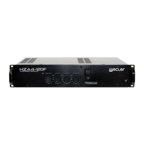
Technical Services. Ecler HZA4-120F comes with a 3-year warranty. INTRODUCTION The HZA4-120F is a four-channel power amplifier with high impedance (100V line) directly amplified outputs. 4.1. Main Features • Internal structure with four separate mono amplifiers, for 4 different mono input signals. -
Page 6: Installation
5.2. Mains connection The HZA4-120F amplifiers are fed with alternate currents, depending on the country, of 110-120, 220-240V 47-63Hz. (see characteristics in the back of the unit). The amplifier should have an earth connection in good conditions (earth resistance, Rg=30... -
Page 7: Signal Input Connections
5.3. Signal input connections The amplifier HZA4-120F features 4 balanced and line level analog signal inputs (one per amplification channel) on its rear panel. Signal input connectors are 3 position screw terminal block (40, 41, 43, 45). The wiring HOT or direct signal >... -
Page 8: Output Connections And Channel Linking With The Flexipower Function
FLEXIPOWER 5.4. Output connections and channel linking with the function OUTPUTS The rear panel section is fitted with two position screw terminal block (28, 29, 30, 31) for each amplifier channel. Always respect the relative polarity for outputs (0 and 100 on each output connector), wiring and speakers. -
Page 9: Internal Switches For High-Pass Filters
5.6. Remote control ports for attenuation REMOTE CONTROL The HZA4-120F features 4 remote control ports labeled “ ” (35, 36, 37, 38) on its rear panel. You can connect WPm series, REVO control panels etc. to each of these ports to remotely attenuate the input signal (and therefore, the output volume of affected channels). -
Page 10: Operation And Usage
To turn them off the sequence should follow an inverse pattern. 6.2. Front panel LED indicators The HZA4-120F is equipped with the following front panel LEDs: STBY •... -
Page 11: Front Panel Volume Controls
6.3. Front panel volume controls The front panel features four volume knobs, one per channel, allowing independent adjustment of the maximum output level for each amplifier channel. Remote control ports also allow to adjust the volume of each amplifier channel from a WPm series panel, a potentiometer or other external hardware device;... -
Page 12: Control Panel Functions
CONTROL PANEL FUNCTIONS 8.1. Front Panel Automatic power off indicator, STBY 14 Clip indication, CLIP CH 3 Signal presence, SP CH 1 15 Thermal protection indicator, TH CH 3 Overload indicator, OVL CH 1 16 Merge indicator, MERGE 3 & 4 Clip indication, CLIP CH 1 17 Signal presence, SP CH 4 Thermal protection indicator, TH CH 1... -
Page 13: Rear Panel
8.2. Rear Panel 26 Mains socket 37 Screwable terminal for remote control, CH 2 27 Fuse holder 38 Screwable terminal for remote 28 Output terminals channel 4, CH 4 control, CH 1 29 Output terminals channel 3, CH 3 39 Standby mode selector, AUTO 30 Output terminals channel 2, CH 2 STBY 31 Output terminals channel 1, CH 1... -
Page 14: Diagrams
DIAGRAMS 9.1. Configuration Diagram FACTORY ADJUST High Pass Filter 9.2. Block Diagram... -
Page 15: Technical Characteristics
TECHNICAL CHARACTERISTICS HZA4-120F Output power @ 1% THD 1 Channel 114 WRMS @ 100V line 2 Merged Channels 195 WRMS @ 100V line 4 Merged Channels 290 WRMS @ 100V line 4 Merged Channels 356 WRMS @ 100V line Output power @ 10% THD... - Page 16 product characteristics subject variation production tolerances. NEEC AUDIO BARCELONA S.L. reserves the right to make changes or improvements in the design or manufacturing that may affect these product specifications. For technical queries contact your supplier, distributor or complete the contact form on our website, Support / Technical requests.


Need help?
Do you have a question about the HZA4-120F and is the answer not in the manual?
Questions and answers