
Related Manuals for Ecler essentials eHSA4-60


Summary of Contents for Ecler essentials eHSA4-60
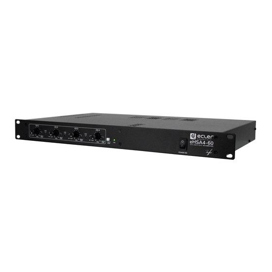
- Page 1 HIGH IMPEDANCE AMPLIFIERS High and low impedance multichannel amplifier USER MANUAL v.20200629...
-
Page 2: Table Of Contents
INDEX IMPORTANT REMARK ......................3 IMPORTANT SAFETY INSTRUCTIONS ................3 IMPORTANT NOTE ........................5 INTRODUCTION ........................5 4.1 Main features ..........................5 INSTALLATION .......................... 6 5.1 Placement, mounting, cooling ....................6 5.2 Mains connection ......................... 6 5.3 Input signal connections ......................7 5.4 Power saving mode........................ -
Page 3: Important Remark
1. IMPORTANT REMARK The lightning flash with arrowhead symbol, within an equilateral triangle, is intended to alert the user to the presence of uninsulated “dangerous voltage” within the product’s enclosure that may be of sufficient magnitude to constitute a risk of electric shock to persons. The exclamation point within an equilateral triangle is intended to alert the user to the presence of important operating and maintenance (servicing) instructions in the literature accompanying the appliance. - Page 4 9. Do not defeat the safety purpose of the polarized or grounding type plug. A polarized plug has two blades with one wider than the other. A grounding type plug has two blades and a third grounding prong. The wide blade or the third prong are provided for your safety.
-
Page 5: Important Note
Ecler eHSA comes with a 3-year warranty. 4. INTRODUCTION eHSA4-60 is a 4x60W multichannel amplifier capable of working on both low impedance lines (8 / 4 Ω) and high impedance lines (70/100V). It has the ability to link the input channels, so that the same input signal can be easily distributed to several or all output channels. -
Page 6: Installation
• Built-in, always active anticlip circuit • Balanced inputs on Euroblock connectors • Powered outputs on Euroblock connectors 5. INSTALLATION Non-compliance with the instructions may cause malfunction and may even damage the unit: 1. Avoid turning on the device without speakers connected to its outputs and without having previously adjusted the volume / gain controls at minimum level. -
Page 7: Input Signal Connections
5.3 Input signal connections The signal input connectors are of EUROBLOCK and electronically balanced. The pin assignment is as follows: • Hot or direct signal > • Cold or phase inverted signal > • Ground > Ground For unbalanced connections, ground the negative terminal on the Euroblock. In balanced mode, the input impedance is greater than 20k Ω... -
Page 8: Limiter Circuit
If you detect that the auto standby function is regularly and/or unexpectedly activated (i.e. even if there is valid sound content at the amplifier's input), before changing the threshold, check that the input signal level setting is adequate. For this purpose, the SP (Signal Present) LED should be active when an audio signal is present, and the CLIP LED should not light up or light up occasionally in line with the bass frequencies, which have the highest energy content. -
Page 9: Output Connections
5.6 Output connections The output section on the rear panel features Euroblock connectors. Connection to high impedance lines: The loudspeakers line has to be connected to the amplifier’s 0V and 70V terminals (70V line) or 0V and 100V terminals (100V line). Connection on low impedance lines: The connection of the speaker line to the amplifier should be made using the Lo-Z ("+"... -
Page 10: Operation And Usage
6. OPERATION AND USAGE 6.1 Start up The red "PROT/STBY" LEDs light up when you turn on the power switch. A second after all voltages have been stabilized and the amplifier is operating, "PROT/STBY" indicators turn off. In a complete audio installation, it is important to power on the equipment according to the following sequence: sound sources (microphones, music players, etc.), mixers, equalizers, active filters and power amplifiers. -
Page 11: Cleaning
CLIP indicators light up when the signal level feeding the loudspeakers is just below the actual clipping. This CLIP system takes into account possible variations in the supply voltage, always giving a real indication. CLIP indicators light up to the beat of low frequencies when working at high power levels;... -
Page 12: Function Diagram
8. FUNCTION DIAGRAM... -
Page 13: Function List
9. FUNCTION LIST 1. LED indicator of signal presence at the channel input: SP 2. Channel trim LED indicator: CLIP 3. Channel input attenuator: CH1, 2, 3… 4. LED indicator for overload protection and status STANDBY, PROT/STBY 5. LED indicator for linked inputs, LINK 6. -
Page 14: Block Diagram
10. BLOCK DIAGRAM... -
Page 15: Technical Characteristics
11. TECHNICAL CHARACTERISTICS eHSA4-60 Output power Max output power¹ @ 4Ω Max output power¹ @ 100V Signal Input sensitivity 0dBV Input impedance >20kΩ Frequency response Lo-Z output @ 4Ω: 70Hz - 30kHz (-3dB) Hi-Z output @ 100V: 70Hz - 20kHz (-3dB) THD + Noise Lo-Z output @ 4Ω: <0,06%... - Page 16 product characteristics subject variation production tolerances. NEEC AUDIO BARCELONA S.L. reserves the right to make changes or improvements in design or manufacture that may affect these product specifications. For technical queries please contact your supplier, distributor or complete the contact form on our website under Support / Technical Query.
Need help?
Do you have a question about the eHSA4-60 and is the answer not in the manual?
Questions and answers