Table of Contents
Advertisement
Quick Links
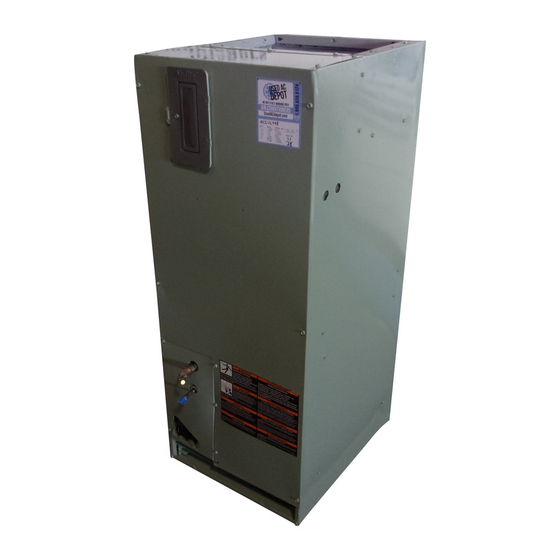
Installer's Guide
1-1/2 - 3 Ton Air Handlers
Upflow / Horizontal Left
2/4TGB3F18A
2/4TGB3F30A
WARNING:
ALL phases of this installation must comply with NATIONAL, STATE AND LOCAL CODES
IMPORTANT - This Document is customer property and is to remain with this unit. Please return to service informa-
tion pack upon completion of work.
A. GENERAL INFORMATION
WARNING
▲
!
THIS INFORMATION IS FOR USE BY INDIVIDUALS
HAVING ADEQUATE BACKGROUNDS OF ELECTRICAL
AND MECHANI CAL EXPERIENCE. ANY ATTEMPT TO
REPAIR A CENTRAL AIR CONDITIONING PRODUCT
MAY RESULT IN PERSONAL INJURY AND/OR PROP-
ERTY DAMAGE. THE MANUFACTURER OR SELLER
CANNOT BE RESPONSIBLE FOR THE INTERPRETA-
TION OF THIS INFORMATION, NOR CAN IT ASSUME
ANY LIABILITY IN CONNECTION WITH ITS USE.
CAUTION
▲
!
To prevent shortening its service life, the air handler
should not be used during the finishing phases of con-
struction. The low return air temperatures can lead to
the formation of condensate. Condensate in the pres-
ence of chlorides and fluorides from paint, varnish,
stains, adhesives, cleaning compounds, and cement
creates a corrosive condition which may cause rapid
deterioration of the cabinet and internal components.
These instructions do not cover all variations in sys-
tems or provide for every possible contingency. Should
further information be desired or particular problems
arise which are not covered sufficiently by this manu-
al, contact your local distributor or the manufacturer
as listed on the air handler nameplate.
These Air Handlers are vertical upflow and horizontal
left configuration only. Refer to Section B beginning
on page 2 for additional information.
INSPECTION
Check carefully for any shipping damage. This must be
reported to and claims made against the transporta-
tion company immediately. Check to be sure all major
components are in the unit. Any missing parts should
be reported to your supplier at once, and replaced with
authorized parts only.
© 2008 Trane
2/4TGB3F25A
2/4TGB3F36A
HAZARDOUS VOLTAGE - DISCONNECT POWER BEFORE SERVICING
Contents
General Information ............................................... 1
Installation Limitations & Recommendations ............................
Unit Installation ...................................................... 2
Vertical Upflow .........................................................................
Horizontal Left ..........................................................................
Refrigerant Piping .................................................. 3
Condensate Drain Piping ...................................... 3
Electrical - Wiring ................................................... 4
Hook Up Diagrams .................................................. 5
Outline Drawings .................................................... 7
Checkout Procedures ............................................. 8
INSTALLATION LIMITATIONS & RECOMMENDATIONS
The general location of the air handler is normally se-
lected by the architect, contractor and/or home owner
for the most effective application and satisfaction.
These air handlers are suitable for installation in a
closet, alcove or utility room with free, non-ducted, air
return, using the area space as a return air plenum.
With ducted supply air, if the minimum clearances to
combustible materials and service access are observed,
the above installations are suitable.
NOTE: Condensation may occur on the sur-
face of the air handler when installed in an
unconditioned location. When units are in-
stalled in unconditioned spaces, verify that
all electrical and refrigerant line penetrations
on the air handler are sealed completely.
This area may also be used for other purposes, includ-
ing an electric hot water heater - but in no case shall
a fossil fuel device be installed and/or operated
in the same closet, alcove or utility room.
18-GD06D1-5
Available in French Canadian (FC)
1
2
2
Advertisement
Table of Contents

Related Manuals for Trane 4TGB3F18A


Summary of Contents for Trane 4TGB3F18A
-
Page 1: Table Of Contents
- but in no case shall be reported to your supplier at once, and replaced with a fossil fuel device be installed and/or operated authorized parts only. in the same closet, alcove or utility room. © 2008 Trane... -
Page 2: Unit Installation
Installer’s Guide In addition, these air handlers are suitable for instal- 10. Make sure there are provisions for installing con- lation in an attic, garage or crawl space with ducted densate drain lines. supply and return air. 11. Route refrigerant & condensate drain lines away This equipment (for models 2/4TGB3F18, 25, 30, 36A from air handler so they do not interfere with ac- cess panels and filters. -
Page 3: Refrigerant Piping
Installer’s Guide 1. Remove the sealing caps from indoor coil field connec- f. It is always recommended that an auxiliary drain pan be installed under a horizontal air handler (See tions. Condensate Drain Piping) to prevent possible dam- 2. Field supplied tubing should be cut squared-off, ensur- age to ceilings. -
Page 4: Electrical - Wiring
Installer’s Guide 5. Do not use reducing fittings in the condensate drain lines. Manufactured traps 6. Slope the drain lines downward a minimum of 1/4" per foot. 7. Insulate the primary drain to prevent sweating. 8. Provide means for drainage to prevent win- 2"... -
Page 5: Hook Up Diagrams
Installer’s Guide 2/4TGB AIR HANDLERS WITH SINGLE STAGE COOLING, 1 STAGE HEAT 18-GD06D1-5... - Page 6 Installer’s Guide 2/4TGB AIR HANDLERS WITH SINGLE SPEED HEAT PUMP 2/4TGB AIR HANDLERS WITH SINGLE STAGE COOLING AND TWO STAGE HEATING From Dwg. B801081 Rev. 2 18-GD06D1-5...
-
Page 7: Outline Drawings
Installer’s Guide 18-GD06D1-5... -
Page 8: Checkout Procedures
I. CHECKOUT PROCEDURE 1. Check the Air Handler installation in accordance with this instruction. 2. “Operational Procedure” for the system installation can be found in the outdoor unit installer guide and will be compatible with this Air Handler. CHECKOUT PROCEDURES After installation has been completed, it is recommended that the Air Handler be checked against the following checklist.