Emerson Rosemount 975 Series Quick Start Manual
Flame detectors
Hide thumbs
Also See for Rosemount 975 Series:
- Reference manual (36 pages) ,
- Quick start manual (20 pages) ,
- Reference manual (44 pages)

Subscribe to Our Youtube Channel
Related Manuals for Emerson Rosemount 975 Series


Summary of Contents for Emerson Rosemount 975 Series
- Page 1 Quick Start Guide 00825-0200-4975, Rev AD August 2023 Rosemount 975 Series ™ Flame Detectors...
-
Page 2: Table Of Contents
Restrict physical access by unauthorized personnel to protect end users’ assets. This is true for all systems used within the facility. Contents Models............................3 Installing the detector......................... 6 Special conditions for use......................20 Declaration of Conformity......................22 Reference data........................... 24 Emerson.com/Rosemount... -
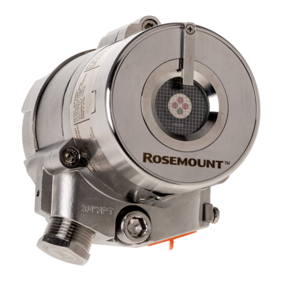
Page 3: Models
The Rosemount 975 series comprises the following detectors: Rosemount 975MR The Rosemount 975MR Ultra Fast Multi-spectrum Triple Infrared... - Page 4 Quick Start Guide August 2023 Table 1-1: Rosemount 975 Series general technical specifications (continued) Response time Varies according to model, typically under 5 seconds Field of view Varies according to model, up to 100 degrees Output 4-20 mA, relays, communication Enclosure...
- Page 5 August 2023 Quick Start Guide NOTICE • If the product is used outside of specified limits, this voids the product certification, and our company is not responsible for any incurred warranty expense. • Do not open this product, except for the terminal compartment as listed in this document, under any circumstances.
-
Page 6: Installing The Detector
Attach detector to tilt mount 2.1.2 Duct mount The duct mount (PN 00975-9000-0002) is suitable for use with the Rosemount 975 series optical flame detector for both the aluminum and stainless steel enclosures. The duct mount allows flame detection in areas where high temperatures exist or in cases where the detector cannot be installed inside the area. - Page 7 August 2023 Quick Start Guide The temperature allowed for the duct mount to be installed is -67 to 392 °F (-55 to 200 °C). For more instructions, refer to the Rosemount 975 Duct Mount Quick Start Guide. Figure 2-1: Duct Mount Quick Start Guide...
- Page 8 For more information, refer to the Pole Mount Quick Start Guide. 2.2 Attach detector to tilt mount Figure 2-2: Tilt mount A. Tilt holding plate B. Horizontal locking screw C. Tilt mount D. Vertical locking screw E. Detector holding plate Emerson.com/Rosemount...
- Page 9 August 2023 Quick Start Guide Figure 2-3: Tilt mount with dimensions Procedure 1. Unpack the detector. 2. The device is provided with two plastic plugs (See image below). The stainless-steel stop plug used to seal the unused conduit will be included in the device. Remember, seal the detector with the stainless-steel plug before use.
- Page 10 5. Point the detector toward the protected area and ensure the view of the area is unobstructed. 6. Secure the detector in that position by tightening the locking screws on the tilt mount. The detector is now correctly located, aligned, and ready to be connected to the system. Emerson.com/Rosemount...
- Page 11 August 2023 Quick Start Guide 2.3 Open the back cover Procedure 1. Loosen the back cover security screw. A. Back cover security screw B. Protective plug 2. Unscrew the back cover. Note The back cover is attached by a security cable. 3.
- Page 12 Quick Start Guide August 2023 2.4 Wire terminals and ground cable NOTICE Improper wiring may damage the detector. Procedure 1. Connect the terminals according to Table 2-3. The terminal details are also on the inside back cover. Figure 2-4: Terminal box Emerson.com/Rosemount...
- Page 13 August 2023 Quick Start Guide Table 2-3: Terminal box Terminal Function 24 VDC (+) 24 VDC (-) External built-in test (BIT) switch Fault relay - normally open (NO) Fault relay Fault relay - normally closed (NC) Alarm relay - NO Alarm relay Alarm relay - NC 0-20 mA (+) 0-20 mA (-)
- Page 14 C. Second detector D. Last detector E. Power supply F. Alarm loop G. End of line Figure 2-6: Non-isolated sink (three wires) A. Detector B. Controller C. Input power: 18 to 32 VDC D. Return E. 0-20 mA meter Emerson.com/Rosemount...
- Page 15 August 2023 Quick Start Guide Figure 2-7: Sink four-wire A. Detector B. Controller C. Input power: 18 to 32 VDC D. Return E. 0-20 mA meter Figure 2-8: Source three-wire A. Detector B. Controller C. Input power: 18-32 VDC D. Return E.
- Page 16 3. Check the wires for secure mechanical connection and press them neatly against the terminal to prevent them from interfering while closing the back cover. 4. Close the terminal compartment by screwing the back cover on to the housing. Emerson.com/Rosemount...
- Page 17 August 2023 Quick Start Guide 5. Tighten the back cover security screw. Figure 2-9: Tilt mount Figure 2-10: Closing security screw A. Back cover security screw B. Ground cable connection point 6. Connect the ground cable. Quick Start Guide...
- Page 18 Plug and seal the unused conduit connection with the provided conduit plug. NOTICE To comply with EMC directive 2014/30/EU and protect against interference caused by radio frequency interference (RFI) and electromagnetic interference (EMI), shield the cable to the detector and ground the detector. Emerson.com/Rosemount...
- Page 19 August 2023 Quick Start Guide 2.5 Install the protective cover NOTICE Always install the protective cover with the detector. The protective cover is available in ABS plastic or stainless steel. Table 2-4: Protective cover Material Part number ABS plastic PN 877263 Stainless steel PN 877163 Procedure...
-
Page 20: Special Conditions For Use
• Flameproof joints are not intended to be repaired. The Rosemount 975 Series Flame Detectors can be fitted with an unmoulded (non-encapsulated), End of Line (EOL) Resistor. Such a resistor can only be fitted into the flameproof ‘Ex d’ compartment as indicated in the instructions. - Page 21 August 2023 Quick Start Guide To reduce the risk of ignition of a flammable or explosive atmosphere, strictly adhere to the following Caution and Warning statements: WARNING Do not open when energized. Do not open when an explosive atmosphere is present. Temperature Increase at cable entry and branching point is 20.9°C.
-
Page 22: Declaration Of Conformity
Quick Start Guide August 2023 4 Declaration of Conformity Figure 4-1: Rosemount 975 Emerson.com/Rosemount... - Page 23 August 2023 Quick Start Guide Quick Start Guide...
-
Page 24: Reference Data
Reference data To view current Rosemount 975 ordering information, specifications, and drawings: Procedure 1. Go to https://www.emerson.com/en-us/catalog/flame- detectors 2. Select the appropriate flame detector. 3. For installation drawings, click Drawings & Schematics and select the appropriate document. 4. For ordering information, specifications, and dimensional drawings, click Data Sheets &... - Page 25 August 2023 Quick Start Guide Quick Start Guide...
- Page 26 Quick Start Guide August 2023 Emerson.com/Rosemount...
- Page 27 August 2023 Quick Start Guide Quick Start Guide...
- Page 28 2023 Emerson. All rights reserved. Emerson Terms and Conditions of Sale are available upon request. The Emerson logo is a trademark and service mark of Emerson Electric Co. Rosemount is a mark of one of the Emerson family of companies. All other marks are the property of their respective owners.
Need help?
Do you have a question about the Rosemount 975 Series and is the answer not in the manual?
Questions and answers