
Related Manuals for Drive 15560


Summary of Contents for Drive 15560
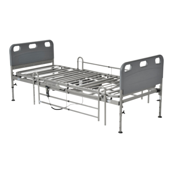
- Page 1 Competitor Ultra Light Plus, Semi Electric Bed Item # 15560, 15560-HR Owner’s Assembly And Operating Manual Note: The competitor bed is available with half-rails (not shown). See page 16 for installation instructions.
- Page 2 Assembly Instructions 1. Remove contents from carton. 2. Place both ends of the sleep surface on their side and align the flange with the receptacle as shown. 3. To attach the head and foot spring, pull the black knob away for the frame and slide the two sides together. The lock knob is spring loaded and will lock into position when released and the two sections of the bed are flush together. To disassemble the head and foot section, pull the black lock knob out and rotate the knob a quarter turn. The lock knob will remain open to allow the head section to be removed from the foot section. REV4.3.5.14...
- Page 3 Assembly Instructions Cont. 4. Secure the sleep surface with the cotter pin as shown. 5. Lock the cotter pin with the attached clasp. Repeat on the opposite side.
-
Page 4: Hand Control
Assembly Instructions Cont. HAND CONTROL The Competitor bed comes with a hand control that will illuminate when the bed is plugged into a grounded or polarized wall outlet, or with 9V battery (not included) installed in the hand control. The hand control will illuminate as long as the wall or battery has power. With this battery installed, the motor can be operated to return the sleep surface to the horizontal position in the event of a power failure. 6. NOTE: Before installing motor, plug hand pendant cable into motor as shown 7. To install motor, remove locking caps on top of the motor. REV4.3.5.14... - Page 5 Assembly Instructions Cont. There are two methods for the installation of the motor Method A The motor is installed on the bed frame when the frame is standing on its side. Installation instructions can be found on pages 7-8. Method B The motor is installed from underneath the bed frame (horizontal to the ground) Installation instructions can be found on pages 10-11.
- Page 6 Assembly Instructions Cont. Method A Installation of the motor when bed frame is on its side A1. Prior to installation, make sure that the 2 white motor blocks are in the retracted position. CORRECT INCORRECT A2. Align the opening on the head end of the Actuator Bar motor with the flange on the head section of the bed and insert the flange into the motor compartment. Flange A3. With the palm of your hand, snap the motor flush to the actuator bar. A4. Align the opening on the foot end of the motor with the flange on the foot section of the bed and insert the flange into the motor compartment.
-
Page 7: Height Adjustment
Assembly Instructions Cont. A6. Once in place, replace the motor covers to secure the motor. A6. Once the motor is attached, lay bed flat and install head and foot boards. There are 2 height adjustments on the head and foot board. Select the desired positions and hook the frame onto the foot board. Slide lock towards leg of foot board to secure position as shown. Repeat for opposite side. HEIGHT ADJUSTMENT 9. The Competitor bed deck has two height adjustments. 10. Adjustment one is located on the frame as indicated below. There is a high position and a low position. 11. Adjustment two is on the leg of the head and foot board. To adjust, loosen the thumb screw on the leg and pull on the spring loaded knob with one hand and slide the leg to the desired height with the other hand. - Page 8 Assembly Instructions Cont. The chart below indicates the height adjustments as they relate to the two adjustment options. Deck Height (inches) Deck Height Pins Leg Hole Wheels 11* Lower Low 13.125 Upper Low Lower Low 14.152 Lower Middle 16.125 Upper Low 16.25 Upper Middle 17.152 Lower Middle 17.875 Lower High 19.25 Upper Middle Upper High 20.875 Lower...
- Page 9 Assembly Instructions Cont. Method B Installation of the motor from underneath the frame B1. Attached head a foot board to frame. B2. Repeat for the other side. Deck Height Pins Upper Lower Leg Holes 1- High 1- Medium 1- Low...
- Page 10 Assembly Instructions Cont. B3. Prior to installation, make sure that the 2 white motor blocks are in the retracted position. CORRECT INCORRECT B4. Remove the covers from the motor and place under the bed and aligned with the actuator under the head section. There are labels on the motor that provide direction and placement in relation to the head section. B5. With both hands, lift the motor and insert into the actuator and frame as shown. With the palm of your hand snap the motor flush to actuator bar. REV4.3.5.14...
- Page 11 Assembly Instructions Cont. B6. Once in place, replace the motor covers to secure the motor. End Method B...
- Page 12 Assembly Instructions Cont. 12. Adjustment two is on the leg of the head and foot board. To adjust, loosen the thumb screw on the leg and pull on the spring loaded knob with one hand and slide the leg to the desired height with the other hand. Once the desired position is found, turn the thumb screw until tight. Adjust other legs to the same position. REV4.3.5.14...
- Page 13 Assembly Instructions Cont. HEIGHT ADJUSTMENT 13. The Competitor bed deck has two height adjustments. 13A. Adjustment one is located on the frame as indicated below. There is a high position and a low position. The chart below indicates the height adjustments as they relate to the two adjustment options. Deck Height (inches) Deck Height Pins Leg Hole Wheels 11* Lower Low 13.125 Upper Low Lower Low 14.152 Lower Middle 16.125 Upper Low 16.25 Upper Middle 17.152 Lower Middle 17.875 Lower High 19.25...
- Page 14 Assembly Instructions Cont. 14. The Competitor bed comes with a caster accessory (sold separately, model # 15044SET). To install the casters, insert the stem of the caster into the leg receptacle as shown. It is recommended to install 1 non-locking caster on each bed end. The locking casters should be installed diagonally from each other. REV4.3.5.14...
- Page 15 Assembly Instructions Cont. 15. To install bed rails, lift the head section and find the rail receptacle located on the frame of the bed as shown. 16. Pull receptacle outward and return head section to the flat position. 17. Turn the receptacle in order to receive the rail. Repeat for all four rail receptacles.
- Page 16 Assembly Instructions Cont. 18. Insert the bed rail into the receptacle. Repeat for the other rail. 19. To install half rails, locate the label located on the head section of the frame. The half rail clamp should be installed over this label. Align fixed clamp jaw in front of bed frame rail as shown below. Align movable clamp jaw on top of bed frame rail, and turn knob clockwise until clamp is tight, securing safety rail to bed frame rail. CORRECT When installing bed rail, only place one (1) rail on bed per side. INCORRECT DO NOT place 2 bed rails on the same side of the bed as shown above. WARNING - INCORRECT MOUNTING MAY CAUSE INJURY OR DEATH REV4.3.5.14...
-
Page 17: Maintenance & Safety Checks
• 5 year warranty on frame. • 5 year warranty on motor. • 5 year on hand control. • 1 year warranty on all other parts and components. During the warranty period, defective items will be replaced at Drive’s option at no charge. NOTE: The competitor bed can be used with a free standing trapeze or a Drive Medical frame mounted trapeze (Item # 15560TRAPEZE). A trapeze cannot be mounted on the Competitor head board. -
Page 18: General Warnings
WARNINGS GENERAL WARNINGS DO NOT use this product or any available optional equipment without first completely reading and under- standing these instructions and any additional instructional material such as owner’s manuals, service manuals or instruction sheets supplied with this product or optional equipment. If you are unable to under- stand the warnings, cautions or instructions, contact a healthcare professional, dealer or technical person- nel before attempting to use this equipment - otherwise, injury or damage may occur. Read all the instructions before using the bed. Refer to the owner’s manuals for beds and rails for additional product and safety information. After any adjustments, repair or service and before use, make sure all attaching hardware is tightened securely. After the bed has been assembled, always test to make sure that all sections of the bed are properly and securely in place before using. ALWAYS use caster locks except when moving the bed. Body weight should be evenly distributed over the surface of the bed. DO NOT lay, sit or lean in such a way that your entire body weight is placed only on raised head or foot sections of the bed. This includes when assisting the user in repositioning or transferring in or out of bed. Check all parts for shipping damage and test before using. In case of damage, DO NOT use. Contact a qualified technician for further instruction. - Page 19 WARNINGS The March 2006 version of the FDA’s bed safety guidelines are published by Hospital Bed Safety Work- group. The latest revision of this document is available at http://www.fda.gov. If the unit is not working properly, call a qualified technician to examine the unit and repair it. Drive Medical products are specifically designed and manufactured for use in conjunction with Drive Medi- cal accessories. Accessories designed by other manufacturers have not been tested by Drive Medical and are not recommended for use with Drive Medical products. Keep all moving parts, including the main frame, mattress deck (head and foot springs/sections) and all drive shafts free of obstruction (i.e. blankets/sheets, heating blankets/pads, tubing, wiring, etc. and other types of products using electric cords which may get tangled around the bed, side rails or legs) during operation of the bed. Keep the product a minimum of 12 inches away from any direct heat source. Make sure head and foot springs/sections are connected securely to the universal bed ends before use. Physically challenged individuals who cannot prevent themselves from rolling/climbing out of the this bed may require alternative safe means of restraint. Procedures other than those described in this manual must be performed by a qualified technician. Risk of injury to persons - DO NOT place video equipment such as televisions or computer monitors on bed. NEVER allow patients to use trapeze or traction units as a total individual weight support. Trapeze units are to be used only for assisting the patient in repositioning or transferring into or out of bed. Trapeze units must be positioned on a universal bed end as near as possible to the center point of the bed end.
- Page 20 WARNINGS The total weight limit of the Drive Medical 36-inch (91.4 cm) wide Manual/Electric bed (including accesso- ries, mattress, occupant and any other person/object positioned on the bed) is 450 pounds (204 kg.); 350 pounds (158 kg) patient weight. Use this bed only for its intended use as described in these instructions. DO NOT use attachments not recommended by the manufacturer. After raising/lowering the head/foot end of the bed, check the distance between the bottom of the bed rail and the mattress. If there is excessive distance between the bottom of the bed rail and the mattress in which individuals may become entangled, adjust the height of the bed rail (if applicable), or provide alter- native means of patient protection. Once patient assessment concludes that the patient’s condition increases the chance of entrapment, the bed MUST be in the flat position when left unattended. Proper patient assessment and monitoring, and proper maintenance and use of equipment is required to reduce the risk of entrapment. Variations in bed rail dimensions, and mattress thickness, size or density could increase the risk of entrapment. Visit the FDA website at http://www.fda.gov to learn about the risks of entrapment.
-
Page 21: Electrical Warnings
WARNINGS BED RAIL WARNINGS Although bed rails are not rated to any specific weight limitation, the bed rails may become deformed or broken if excessive side pressure is exerted on the bed rails. The bed rail is not an assist rail for getting into or out of bed. DO NOT use the bed rails as push handles when moving the bed. Always test to make sure that the side rails are properly and securely in place before using the bed. DO NOT install the optional bed rails without reading and understanding all of the instructions in the in- struction sheet that accompanies the bed rail kit. DO NOT use the side rails as push handles for moving the bed. These bed rails are intended to prevent an individual from inadvertently rolling out of bed. DO NOT use for restraint purposes. - Page 22 WARNINGS DO NOT place pendant under or between objects. This may unintentionally press the buttons and may cause injury or damage. Electronic equipment may be influenced by Radio Frequency Interference (RFI). Caution should be exer- cised with regard to the use of portable communications equipment in the area around such equipment. If RFI causes erratic behavior, unplug the electric bed IMMEDIATELY. Leave unplugged while transmission is in progress. Ensure all cables and cords are routed such that they will not become entangled or pinched. Otherwise damage or injury may result. If a button on the pendant does not release or sticks, the bed spring will not stop moving. If a liquid is spilled in or around the electric bed, unplug the electric bed before cleaning. Clean up the spill and allow the electric bed or the area around the electric bed to dry thoroughly before using the electric controls again.
- Page 23 WARNINGS Use caution when disconnecting the pendant. DO NOT press pendant buttons. When bed is not to be used for an extended period, unplug electric bed from the wall outlet. When using an extension cord, use only a three wire extension cord having at least 16 AWG (American Wire Gauge) wire and the same or higher electrical rating as the device being connected. Use of improper extension cord could result in a risk of fire and electric shock. Three to two prong adapters should not be used. Use of three prong adapters can result in improper grounding and present a shock hazard to the user. When using nasal or masked type oxygen administering equipment, the oxygen or air tubing MUST be routed and secured properly to ensure that the tubing does not become entangled and/or severed during normal operation of the bed. DO NOT use near explosive gases. Possible fire hazard when used with oxygen administering equipment other than nasal or masked type.
- Page 24 99 Seaview Boulevard Port Washington, NY 11050 Phone: 516-998-4600 Toll Free: 877.224.0946 Fax: 516.998.4601 www.drivemedical.com REV4.3.5.14...
Need help?
Do you have a question about the 15560 and is the answer not in the manual?
Questions and answers
Can bed be transported with just removing head and foot rests
No, the Drive 15560 bed cannot be transported by only removing the head and foot rests. Full disassembly requires separating the head and foot spring sections, which involves pulling and rotating a lock knob, as well as removing cotter pins securing the sleep surface. Transport also typically requires removing the motor and other components.
This answer is automatically generated