Arcteq AQ-F201 Instruction Manual
Overcurrent and earth fault relay
Hide thumbs
Also See for AQ-F201:
- Instruction manual (210 pages) ,
- Instruction manual (225 pages) ,
- Instruction manual (245 pages)
Table of Contents
Advertisement
Quick Links
Advertisement
Table of Contents

Subscribe to Our Youtube Channel
Related Manuals for Arcteq AQ-F201


Summary of Contents for Arcteq AQ-F201
- Page 1 AQ-F201 Overcurrent and earth fault relay Instruction manual...
-
Page 2: Table Of Contents
3.9 Configuring user levels and their passwords................. 49 4 Functions unctions ...................................................... 52 4.1 Functions included in AQ-F201.................... 52 4.2 Measurements........................53 4.2.1 Current measurement and scaling ................53 4.2.2 Frequency tracking and scaling ................. 67 4.3 General menu........................70 4.4 Protection functions ...................... - Page 3 6 Connections and applic 6 Connections and applica a tion examples tion examples..................................228 6.1 Connections of AQ-F201 ....................228 6.2 Application example and its connections................228 6.3 Two-phase, three-wire ARON input connection ..............229 6.4 Trip circuit supervision (95) ....................230...
- Page 4 Instruction manual Version: 2.12 9 Or 9 Ordering inf dering informa ormation tion ..............................................260 10 Contact and r 10 Contact and re e f f er erence inf ence informa ormation tion....................................261 © Arcteq Relays Ltd IM00012...
- Page 5 Nothing contained in this document shall increase the liability or extend the warranty obligations of the manufacturer Arcteq Relays Ltd. The manufacturer expressly disclaims any and all liability for any damages and/or losses caused due to a failure to comply with the instructions contained herein or caused by persons who do not fulfil the aforementioned requirements.
-
Page 6: Document Inf
- Complete rewrite of every chapter. Changes - Improvements to many drawings and formula images. - Order codes revised. Revision 2.02 Date 7.7.2020 Changes - A number of image descriptions improved. Revision 2.03 Date 27.8.2020 © Arcteq Relays Ltd IM00012... - Page 7 - Tech data updated: current unbalance - Improvements to many drawings and formula images. - Improved and updated device user interface display images. - AQ-F201 Functions included list Added: Programmable control switches and measurement recorder. - Added 6th harmonic to harmonic overcurrent protection function.
- Page 8 Revision 2.09 Date 14.3.2023 - Updated the Arcteq logo on the cover page and refined the manual's visual look. - Added the "Safety information" chapter and changed the notes throughout the document accordingly. - Changed the "IED user interface" chapter's title to "Device user interface" and replaced all Changes 'IED' terms with 'device' or 'unit'.
-
Page 9: Version 1 Revision Notes
1.2 Version 1 revision notes Table. 1.2 - 2. Version 1 revision notes Revision 1.00 Date 8.1.2013 Changes • The first revision for AQ-F201. Revision 1.01 Date 22.11.2013 • Order code updated, technical data updated. Changes • The "Measurements" chapter added. -
Page 10: Safety Information
W W ARNING! ARNING! "Warning" messages indicate a potentially hazardous situation which, if not avoided, could could result in death or serious personal injury as well as serious damage to equipment/property. © Arcteq Relays Ltd IM00012... -
Page 11: Abbreviations
DHCP – Dynamic Host Configuration Protocol DI – Digital input DO – Digital output DOL – Direct-on-line DR – Disturbance recorder DT – Definite time FF – Fundamental frequency FFT – Fast Fourier transform FTP – File Transfer Protocol © Arcteq Relays Ltd IM00012... - Page 12 SG – Setting group SOTF – Switch-on-to-fault SW – Software THD – Total harmonic distortion TRMS – True root mean square VT – Voltage transformer VTM – Voltage transformer module VTS – Voltage transformer supervision © Arcteq Relays Ltd IM00012...
-
Page 13: General
AQ-F201 overcurrent and earth fault device is a member of the AQ 200 product line. However, while the hardware and the software are modular in the AQ 200 product line, AQ-F201 is provided as a fixed overcurrent and earth fault device with a factory set of I/O and functionality. This manual describes the specific application of the AQ-F201 overcurrent and earth fault device. -
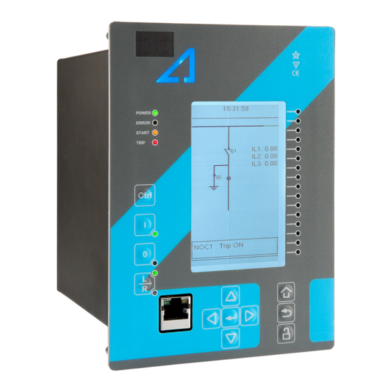
Page 14: Device User Int Vice User Interface Erface
5. Eight (8) buttons for device local programming: the four navigation arrows and the E E nt nter er button in the middle, as well as the Home Home, the Back Back and the password activation buttons. 6. One (1) RJ-45 Ethernet port for device configuration. © Arcteq Relays Ltd IM00012... -
Page 15: Mimic And Main Menu
LEDs you have set. The password activation button (with the padlock icon ) takes you to the password menu where you can enter the passwords for the various user levels (User, Operator, Configurator, and Super-user). © Arcteq Relays Ltd IM00012... -
Page 16: Navigation In The Main Configuration Menus
The General main menu is divided into two submenus: the Device info tab presents the information of the device, while the Function comments tab allows you to view all comments you have added to the functions. © Arcteq Relays Ltd IM00012... - Page 17 A A Q Q -F201 -F201 3 Device user interface Instruction manual Version: 2.12 Figure. 3.3 - 4. General menu structure. Device info Figure. 3.3 - 5. Device info. © Arcteq Relays Ltd IM00012...
- Page 18 Displays the UTC time used by the unit UTC time without time zone corrections. • - Clears the event history recorded in Clear events • - • Clear the device. LCD Contrast 0…255 Changes the contrast of the LCD display. © Arcteq Relays Ltd IM00012...
- Page 19 Monitor profile Function comments Function comments displays notes of each function that has been activated in the Protection, Control and Monitoring menu. Function notes can be edited by the user. Figure. 3.3 - 6. Function comments. © Arcteq Relays Ltd IM00012...
-
Page 20: Protection Menu
The Protection main menu includes the Stage activation submenu as well as the submenus for all the various protection functions, categorized under the following modules: "Arc protection", "Current", "Voltage", "Frequency", "Sequence" and "Supporting" (see the image below). The available functions depend on the device type in use. © Arcteq Relays Ltd IM00012... - Page 21 For example, the I> (overcurrent) protection stage can be found in the "Current" module, whereas the U< (undervoltage) protection stage can be found in the "Voltage" module. Figure. 3.4 - 9. Submenus for Stage activation. © Arcteq Relays Ltd IM00012...
- Page 22 Figure. 3.4 - 10. Accessing the submenu of an individual activated stage. Each protection stage and supporting function has five sections in their stage submenus: "Info", "Settings", " Registers", "I/O" and "Events". Figure. 3.4 - 11. Info. © Arcteq Relays Ltd IM00012...
- Page 23 Voltage and current transformers nominal values can be set at Measurement → Transformers . • Delay type and operating time delay settings are described in detail in General properties of a protection function chapter. © Arcteq Relays Ltd IM00012...
- Page 24 Data included in the register depend on the protection function. You can clear the the operation register by choosing "Clear registers" → "Clear". "General event register" stores the event generated by the stage. These general event registers cannot be cleared. © Arcteq Relays Ltd IM00012...
- Page 25 "Blocking input control" allows you to block stages. The blocking can be done by using any of the following: • digital inputs • logical inputs or outputs • the START, TRIP or BLOCKED information of another protection stage • object status information. © Arcteq Relays Ltd IM00012...
-
Page 26: Control Menu
, for configuring the objects ( Objects) , for setting the various control functions ( Control functions) , and for configuring the inputs and outputs ( Device I/O) . The available control functions depend on the model of the device in use. © Arcteq Relays Ltd IM00012... - Page 27 • F F or orce se ce set t ting gr ting group change oup change: this setting allows the activation of a setting group at will (please note that Force SG change enable must be "Enabled"). © Arcteq Relays Ltd IM00012...
- Page 28 Each activated object is visible in the Objects submenu. By default all objects are disabled unless specifically activated in the Controls → Controls enabled submenu. Each active object has four sections in their submenus: "Settings", "Application control" ("App contr"), "Registers" and "Events". These are described in further detail below. © Arcteq Relays Ltd IM00012...
- Page 29 A request is considered to have failed when the object does not change its status as a result of that request. • C C lear sta lear statistics tistics: statistics can be cleared by choosing "Clear statistics" and then "Clear". © Arcteq Relays Ltd IM00012...
- Page 30 By default, the access level is set to "Configurator". • You can use digital inputs to control the object locally or remotely. Remote controlling via the bus is configured on the protocol level. © Arcteq Relays Ltd IM00012...
- Page 31 Object blocking is done in the "Blocking input control" subsection. It can be done by any of the following: digital inputs, logical inputs or outputs, object status information as well as stage starts, trips or blocks. Figure. 3.5 - 23. Registers section. © Arcteq Relays Ltd IM00012...
- Page 32 In the image series below, the user has activated three control functions. The user accesses the list of activated control stages through the "Control functions" module, and selects the control function for further inspection. Figure. 3.5 - 25. Control functions submenu. © Arcteq Relays Ltd IM00012...
- Page 33 While the function is activated and disabled in the Control → Controls enabled submenu, you can disable the function through the "Info" section (the [function name] mode at the top of the section). Figure. 3.5 - 27. Settings section. © Arcteq Relays Ltd IM00012...
- Page 34 Data included in the register depend on the control function. You can clear the the operation register by choosing "Clear registers" → "Clear". "General event register" stores the event generated by the stage. These general event registers cannot be cleared. © Arcteq Relays Ltd IM00012...
- Page 35 "Blocking input control" allows you to block stages. The blocking can be done by using any of the following: • digital inputs. • logical inputs or outputs. • the START, TRIP or BLOCKED information of another protection stage. • object status information. © Arcteq Relays Ltd IM00012...
- Page 36 Mimic Indicator", "Logic signals" and "GOOSE matrix". Please note that digital inputs, logic outputs, protection stage status signals (START, TRIP, BLOCKED, etc.) as well as object status signals can be connected to an output relay or to LEDs in the "Device I/O matrix" section. © Arcteq Relays Ltd IM00012...
- Page 37 "Event masks" subsection you can determine which events are masked –and therefore recorded into the event history– and which are not. Figure. 3.5 - 33. Digital outputs section. All settings related to digital outputs can be found in the "Digital outputs" section. © Arcteq Relays Ltd IM00012...
- Page 38 LED quick displays and the matrices. You can also modify the color of the LED ("LED color settings") between green and yellow; by default all LEDs are green. © Arcteq Relays Ltd IM00012...
- Page 39 These signals can be used in a variety of situations, such as for controlling the logic program, for function blocking, etc. You can name each switch and set the access level to determine who can control the switch. © Arcteq Relays Ltd IM00012...
- Page 40 Logical output signals can be used as the end result of a logic that has been built in the AQtivate 200 setting tool. The end result can then be connected to a digital output or a LED in the matrix, block functions and much more. © Arcteq Relays Ltd IM00012...
-
Page 41: Communication Menu
Connecting to AQtivate requires knowing the IP address of your device: this can be found in the Communication → Connections submenu. As a standard, the devices support the following communication protocols: • NTP • Modbus/TCP • Modbus/RTU • IEC-103 • IEC -101/104 • SPA • DNP3 • ModbusIO. © Arcteq Relays Ltd IM00012... - Page 42 When communicating with a device via the front Ethernet port connection, the IP address is always 192.168.66.9. SERIAL COM1 & COM2 SERIAL COM1 & COM2 SERIAL COM1 and SERIAL COM2 are reserved for serial communication option cards. They have the same settings as the RS-485 port. © Arcteq Relays Ltd IM00012...
- Page 43 • DNP3: supports both serial and Ethernet communication. • ModbusIO: used for connecting external devices like ADAM RTD measurement units. NOTICE! TICE! Please refer to the "Communication" chapter for a more detailed text on the various communication options. © Arcteq Relays Ltd IM00012...
-
Page 44: Measurement Menu
Transformers menu is used for setting up the measurement settings of available current transformer modules or voltage transformer modules. Some unit types have more than one CT or VT module. Some unit types like AQ-S214 do not have current or voltage transformers at all. © Arcteq Relays Ltd IM00012... - Page 45 The CT module submenu also displays additional information such as CT scaling factors and per-unit scaling factors. Frequency Figure. 3.7 - 45. Frequency submenu. © Arcteq Relays Ltd IM00012...
- Page 46 (IL1, IL2, IL3) as well as the two residual currents (I01, I02); each component can be displayed as absolute or percentage values, and as primary or secondary amperages or in per-unit values. © Arcteq Relays Ltd IM00012...
-
Page 47: Monitoring Menu
( Disturbance REC ) and accessing the device diagnostics ( Device diagnostics ). The available monitoring functions depend on the type of the device in use. Figure. 3.8 - 48. Monitoring menu view. © Arcteq Relays Ltd IM00012... - Page 48 Configuring monitor functions is very similar to configuring protection and control stages. They, too, have the five sections that display information ("Info"), set the parameters ("Settings"), show the inputs and outputs ("I/O") and present the events and registers ("Events" and "Registers"). © Arcteq Relays Ltd IM00012...
- Page 49 • "Pretriggering time" can be selected between 0.1…15.0 s. • The device can record up to 20 (20) analog channels that can be selected from the twenty (20) available channels. Every measured current or voltage signal can be selected to be recorded. © Arcteq Relays Ltd IM00012...
-
Page 50: Configuring User Levels And Their Passwords
L L ock ock button in the device's HMI and set the desired passwords for the different user levels. NOTICE! TICE! Passwords can only be set locally in an HMI. © Arcteq Relays Ltd IM00012... - Page 51 As mentioned above, the access level of the different user levels is indicated by the number of stars. The required access level to change a parameter is indicated with a star (*) symbol if such is required. As a general rule the access levels are divided as follows: © Arcteq Relays Ltd IM00012...
- Page 52 • Super user: Can change any setting and can operate breakers and other equipment. NOTICE! TICE! Any user level with a password automatically locks itself after half an hour (30 minutes) of inactivity. © Arcteq Relays Ltd IM00012...
-
Page 53: Functions Unctions
Version: 2.12 4 Functions 4.1 Functions included in AQ-F201 The AQ-F201 overcurrent and earth fault device includes the following functions as well as the number of stages for those functions. Table. 4.1 - 4. Protection functions of AQ-F201. Name (number... -
Page 54: Measurements
It is essential to understand the concept of current measurements to be able to get correct measurements. Figure. 4.2.1 - 53. Current measurement terminology. © Arcteq Relays Ltd IM00012... - Page 55 Example of CT scaling The following figure presents how CTs are connected to the device's measurement inputs. It also shows example CT ratings and nominal current of the load. © Arcteq Relays Ltd IM00012...
- Page 56 CT primary value. If the CT values are chosen to be the basis for the per-unit scaling, the option "CT nom. p.u." is selected for the "Scale meas to In" setting (see the image below). © Arcteq Relays Ltd IM00012...
- Page 57 Next, we set the residual IO CT scalings according to how the phase current CTs and the ring core CT are connected to the module (see the Connections image at the beginning of this chapter). © Arcteq Relays Ltd IM00012...
- Page 58 CT primary values are the basis for the scaling; the second shows them when the protected object's nominal current is the basis for the scaling. Figure. 4.2.1 - 59. Scalings display (based on the CT nominal). © Arcteq Relays Ltd IM00012...
- Page 59 I02 channel which has lower CT scaling ranges (see the image below). Figure. 4.2.1 - 61. Connections of ZCT scaling. Troubleshooting When the measured current values differ from the expected current values, the following table offers possible solutions for the problems. © Arcteq Relays Ltd IM00012...
- Page 60 The following image presents the most common problems with phase polarity. Problems with phase polarity are easy to find because the vector diagram points towards the opposite polarity when a phase has been incorrectly connected. © Arcteq Relays Ltd IM00012...
- Page 61 If two phases are mixed together, the network rotation always follows the pattern IL1-IL3-IL2 and the measured negative sequence current is therefore always 1.00 (in. p.u.). © Arcteq Relays Ltd IM00012...
- Page 62 • Invert connector 6, with the secondary currents' starpoint pointing towards the line. A feedback value; the calculated scaling factor that is CT scaling the ratio between the primary current and the factor P/S secondary current. © Arcteq Relays Ltd IM00012...
- Page 63 9 to connector A feedback value; the calculated scaling factor that is the scaling ratio between the primary current and the secondary factor P/S current. Measurements The following measurements are available in the measured current channels. © Arcteq Relays Ltd IM00012...
- Page 64 TRMS Sec") Table. 4.2.1 - 14. Phase angle measurements. Name Unit Range Step Description Phase angle The phase angle measurement from each of the three phase 0.00…360.00 0.01 ("Pha.angle current inputs. ILx") © Arcteq Relays Ltd IM00012...
- Page 65 I0. ("Sec.calc.I0") Secondary residual The secondary TRMS current (inc. harmonics up to 31 current I0x TRMS 0.00…300.00 0.01 measurement from the secondary residual current channel (Res.curr.I0x TRMS I01 or I02. Sec") © Arcteq Relays Ltd IM00012...
- Page 66 Secondary positive sequence current The secondary measurement from the calculated 0.00…300.00 0.01 ("Sec.Positive sequence positive sequence current. curr.") Secondary negative sequence current The secondary measurement from the calculated 0.00…300.00 0.01 ("Sec.Negative sequence negative sequence current. curr") © Arcteq Relays Ltd IM00012...
- Page 67 Displays the selected harmonic from the current input ILx or 0.01 ...31 000.00 I0x. harmonic) Ixx Amplitude % 0.000...100.000 0.001 Amplitude ratio THD voltage. Recognized by IEC. Ixx Power THD % 0.000...100.000 0.001 Power ratio THD voltage. Recognized by the IEEE. © Arcteq Relays Ltd IM00012...
-
Page 68: Frequency Tracking And Scaling
FFT calculation always has a whole power cycle in the buffer. The measurement accuracy is further improved by Arcteq's patented calibration algorithms that calibrate the analog channels against eight (8) system frequency points for both magnitude and angle. - Page 69 CT1IL1 The first reference source for frequency tracking. reference 1 • VT1U1 • VT2U1 • None • CT1IL2 Frequency The second reference source for frequency • CT2IL2 CT1IL2 reference 2 tracking. • VT1U2 • VT2U2 © Arcteq Relays Ltd IM00012...
- Page 70 Displays the rough value of the tracked frequency 0.000…75.000Hz 0.001Hz - channel C in Channel C. • One f measured System • Two f Displays the amount of frequencies that are measured measured measured. frequency • Three f measured © Arcteq Relays Ltd IM00012...
-
Page 71: General Menu
The order code identification of the unit. System phase rotating order at The selected system phase rotating order. Can be changed with parameter the moment "System phase rotating order". UTC time The UTC time value which the device's clock uses. © Arcteq Relays Ltd IM00012... - Page 72 When a reset command is given, the parameter • Reset automatically returns back to "-". • Disabled Enables the measurement recorder tool, further Measurement recorder Disabled • Enabled configured in Tools → Misc → Measurement recorder. © Arcteq Relays Ltd IM00012...
-
Page 73: Protection Functions
4.4.1 General properties of a protection function The following flowchart describes the basic structure of any protection function. The basic structure is composed of analog measurement values being compared to the pick-up values and operating time characteristics. © Arcteq Relays Ltd IM00012... - Page 74 A A Q Q -F201 -F201 4 Functions Instruction manual Version: 2.12 The protection function is run in a completely digital environment with a protection CPU microprocessor which also processes the analog signals transformed into the digital form. © Arcteq Relays Ltd IM00012...
- Page 75 ). The reset ratio of 97 % is built into the function and is always relative to the X value. If a function's pick-up characteristics vary from this description, they are defined in the function section in the manual. Figure. 4.4.1 - 65. Pick up and reset. © Arcteq Relays Ltd IM00012...
- Page 76 (independent time characteristics). • Inverse definite minimum time (IDMT): activates the trip signal after a time which is in relation to the set pick-up value X and the measured value X (dependent time characteristics). © Arcteq Relays Ltd IM00012...
- Page 77 Selects whether the delay curve series for an IDMT operation follows either IEC or IEEE/ANSI standard Delay curve • IEC defined characteristics. series • IEEE This setting is active and visible when the "Delay type" parameter is set to "IDMT". © Arcteq Relays Ltd IM00012...
- Page 78 "Param". Defines the Constant C for IEEE characteristics. This setting is active and visible when the "Delay type" 0.0000…250.0000 0.0001 0.0200 parameter is set to "IDMT" and the "Delay characteristic" parameter is set to "Param". © Arcteq Relays Ltd IM00012...
- Page 79 NOTE TE: : when "k" has been set lower than 0.3 calculated operation time can be lower with mechanical relays. than 0 seconds with some measurement values. In these cases operation time will be instant. © Arcteq Relays Ltd IM00012...
- Page 80 • Yes even if the pick-up element is reset. release time The behavior of the stages with different release time configurations are presented in the figures below. © Arcteq Relays Ltd IM00012...
- Page 81 A A Q Q -F201 -F201 4 Functions Instruction manual Version: 2.12 Figure. 4.4.1 - 69. No delayed pick-up release. Figure. 4.4.1 - 70. Delayed pick-up release, delay counter is reset at signal drop-off. © Arcteq Relays Ltd IM00012...
- Page 82 Figure. 4.4.1 - 72. Delayed pick-up release, delay counter value is decreasing during the release time. The resetting characteristics can be set according to the application. The default setting is delayed 60 ms and the time calculation is held during the release time. © Arcteq Relays Ltd IM00012...
-
Page 83: Non-Directional Overcurrent Protection (I>; 50/51)
32 components, or to peak-to-peak values. Table. 4.4.2 - 32. Measurement inputs of the I> function. Signal Description Time base Fundamental frequency component of phase L1 (A) current measurement Fundamental frequency component of phase L2 (B) current measurement © Arcteq Relays Ltd IM00012... - Page 84 • Start CA • Start • Trip AB • Trip BC • Trip CA • Trip • RMS Measured • TRMS Defines which available measured magnitude is used by the magnitude • Peak-to- function. peak © Arcteq Relays Ltd IM00012...
- Page 85 Time When the function has detected a fault and counts down time remaining -1800.000...1800.000s 0.005s towards a trip, this displays how much time is left before tripping to trip occurs. © Arcteq Relays Ltd IM00012...
- Page 86 The function's outputs can be used for direct I/O controlling and for user logic programming. The function also provides a resettable cumulative counter for the START, TRIP and BLOCKED events. Table. 4.4.2 - 37. Event messages. Event block name Event names NOC1...NOC3 Start ON NOC1...NOC3 Start OFF © Arcteq Relays Ltd IM00012...
- Page 87 Event Event name Fault type L1-E…L1-L2-L3 Pre-trigger current Start/Trip -20ms current Fault current Start/Trip current Pre-fault current Start -200ms current Trip time remaining 0 ms...1800s Setting group in use Setting group 1...8 active. © Arcteq Relays Ltd IM00012...
-
Page 88: Non-Directional Earth Fault Protection (I0>; 50N/51N)
Fundamental frequency component of the zero sequence current calculated from the 0Calc three phase currents General settings The following general settings define the general behavior of the function. These settings are static i.e. it is not possible to change them by editing the setting group. © Arcteq Relays Ltd IM00012... - Page 89 Live Edit mode is active. Table. 4.4.3 - 42. Information displayed by the function. Name Range Step Description • Normal I0> • Start Displays status of the protection function. condition • Trip • Blocked © Arcteq Relays Ltd IM00012...
- Page 90 The variables the user can set are binary signals from the system. The blocking signal needs to reach the device minimum of 5 ms before the set operating delay has passed in order for the blocking to activate in time. © Arcteq Relays Ltd IM00012...
- Page 91 Event Event name Fault type A-G-R…C-G-F Pre-trigger current Start/Trip -20ms current Fault current Start/Trip current Pre-fault current Start -200ms current Trip time remaining 0 ms...1800s Setting group in use Setting group 1...8 active. © Arcteq Relays Ltd IM00012...
-
Page 92: Negative Sequence Overcurrent/ Phase Current Reversal/ Current Unbalance Protection (I2>; 46/46R/46L)
Negative sequence current magnitude 5 ms Zero sequence current magnitude 5 ms I1 ANG Positive sequence current angle 5 ms I2 ANG Negative sequence current angle 5 ms IZ ANG Zero sequence current angle 5 ms © Arcteq Relays Ltd IM00012... - Page 93 The function's Info page displays useful, real-time information on the state of the protection function. It is accessed either through the device's HMI display, or through the setting tool software when it is connected to the device and its Live Edit mode is active. © Arcteq Relays Ltd IM00012...
- Page 94 Unique to the current unbalance protection is the availability of the “Curve2” delay which follows the formula below: • t = Operating time • I = Calculated negative sequence 2meas • k = Constant k value (user settable delay multiplier) • I = Pick-up setting of the function © Arcteq Relays Ltd IM00012...
- Page 95 The function's outputs can be used for direct I/O controlling and user logic programming. The function also provides a resettable cumulative counter for the START, TRIP and BLOCKED events. The function offers one (1) independent stage. Table. 4.4.4 - 49. Event messages. Event block name Event names CUB1 Start ON © Arcteq Relays Ltd IM00012...
-
Page 96: Harmonic Overcurrent Protection (Ih>; 50H/51H/68H)
The number of stages in the function depends on the relay model. The function constantly measures the selected harmonic component of the selected measurement channels, the value being either absolute value or relative to the RMS value. © Arcteq Relays Ltd IM00012... - Page 97 The magnitudes (RMS) of phase L1 (A) current components: - Fundamental harmonic harmonic harmonic harmonic harmonic 5 ms harmonic harmonic - 11 harmonic - 13 harmonic - 15 harmonic - 17 harmonic - 19 harmonic. © Arcteq Relays Ltd IM00012...
- Page 98 The magnitudes (RMS) of residual I0 current components: - Fundamental harmonic harmonic harmonic harmonic harmonic 5 ms harmonic harmonic - 11 harmonic - 13 harmonic - 15 harmonic - 17 harmonic - 19 harmonic. © Arcteq Relays Ltd IM00012...
- Page 99 Name Range Default Description • Normal Ih> force • Start Force the status of the function. Visible only when Enable stage Normal forcing parameter is enabled in General menu. status to • Trip • Blocked © Arcteq Relays Ltd IM00012...
- Page 100 (in single, dual or all phases) it triggers the pick-up operation of the function. Setting group selection controls the operating characteristics of the function, i.e. the user or user- defined logic can change function parameters while the function is running. © Arcteq Relays Ltd IM00012...
- Page 101 The variables the user can set are binary signals from the system. The blocking signal needs to reach the device minimum of 5 ms before the set operating delay has passed in order for the blocking to activate in time. © Arcteq Relays Ltd IM00012...
- Page 102 Table. 4.4.5 - 56. Register content. Register Description Date and time dd.mm.yyyy hh:mm:ss.mss Event Event name Fault type L1-E…L1-L2-L3 Pre-trigger current Start/Trip -20ms current Fault current Start/Trip current Pre-fault current Start -200ms current Trip time remaining 0.000s ... 1800.000s © Arcteq Relays Ltd IM00012...
-
Page 103: Circuit Breaker Failure Protection (Cbfp; 50Bf/52Bf)
The user can select I01, I02 or the calculated I0 for the residual current measurement. Table. 4.4.6 - 57. Measurement inputs of the CBFP function. Signal Description Time base Fundamental frequency component of phase L1 (A) current measurement © Arcteq Relays Ltd IM00012... - Page 104 (in single, dual or all phases) it triggers the pick-up operation of the function. Setting group selection controls the operating characteristics of the function, i.e. the user or user- defined logic can change function parameters while the function is running. © Arcteq Relays Ltd IM00012...
- Page 105 The function's Info page displays useful, real-time information on the state of the protection function. It is accessed either through the device's HMI display, or through the setting tool software when it is connected to the device and its Live Edit mode is active. © Arcteq Relays Ltd IM00012...
- Page 106 CBFP starts the timer. This setting defines how long the CBFP 0.000…1800.000s 0.005s 0.200s starting condition has to last before the CBFP signal is activated. The following figures present some typical cases of the CBFP function. © Arcteq Relays Ltd IM00012...
- Page 107 The retrip is wired from its own device output contact in parallel with the circuit breaker's redundant trip coil. The CBFP signal is normally wired from its device output contact to the incoming feeder circuit breaker. Below are a few operational cases regarding the various applications. © Arcteq Relays Ltd IM00012...
- Page 108 CBFP signal to the incoming feeder breaker. If the primary protection function clears the fault, both counters (RETRIP and CBFP) are reset as soon as the measured current is below the threshold settings. © Arcteq Relays Ltd IM00012...
- Page 109 (RETRIP and CBFP) are reset as soon as the measured current is below the threshold settings or the tripping signal is reset. This configuration allows the CBFP to be controlled with current- based functions alone, and other function trips can be excluded from the CBFP functionality. © Arcteq Relays Ltd IM00012...
- Page 110 This configuration allows the CBFP to be controlled with current-based functions alone, with added security from current monitoring. Other function trips can also be included in the CBFP functionality. © Arcteq Relays Ltd IM00012...
- Page 111 Probably the most common application is when the device's trip output controls the circuit breaker trip coil, while one dedicated CBFP contact controls the CBFP function. Below are a few operational cases regarding the various applications and settings of the CBFP function. © Arcteq Relays Ltd IM00012...
- Page 112 CBFP signal is sent to the incoming feeder circuit breaker. If the primary protection function clears the fault, the counter for CBFP resets as soon as the measured current is below the threshold settings. © Arcteq Relays Ltd IM00012...
- Page 113 This configuration allows the CBFP to be controlled by current-based functions alone, and other function trips can be excluded from the CBFP functionality. © Arcteq Relays Ltd IM00012...
- Page 114 This configuration allows the CBFP to be controlled by current-based functions alone, with added security from current monitoring. Other function trips can also be included to the CBFP functionality. © Arcteq Relays Ltd IM00012...
- Page 115 A A Q Q -F201 -F201 4 Functions Instruction manual Version: 2.12 Device configuration as a dedicated CBFP unit Figure. 4.4.6 - 87. Wiring diagram when the device is configured as a dedicated CBFP unit. © Arcteq Relays Ltd IM00012...
- Page 116 The function's outputs can be used for direct I/O controlling and user logic programming. The function also provides a resettable cumulative counters for RETRIP, CBFP, CBFP START and BLOCKED events. Table. 4.4.6 - 64. Event messages. Event block name Event names CBF1 Start ON CBF1 Start OFF © Arcteq Relays Ltd IM00012...
-
Page 117: Line Thermal Overload Protection (Tf>; 49F)
This function can also be used for any single time constant application like inductor chokes, certain types of transformers and any other static units which do not have active cooling apart from the cables and overhead lines. © Arcteq Relays Ltd IM00012... - Page 118 100 % indefinitely but never exceeds it. With a single time constant model the cooling of the object follows this same behavior, the reverse of the heating when the current feeding is zero. © Arcteq Relays Ltd IM00012...
- Page 119 The ambient temperature compensation takes into account the set minimum and maximum temperatures and the load capacity of the protected object as well as the measured or set ambient temperature. The calculated coefficient is a linear correction factor, as the following formula shows: © Arcteq Relays Ltd IM00012...
- Page 120 As can be seen in the diagram above, the ambient temperature coefficient is relative to the nominal temperature reference. By default the temperature reference is +15 °C (underground cables) which gives the correction factor value of 1.00 for the thermal replica. © Arcteq Relays Ltd IM00012...
- Page 121 The temperature coefficient may be informed in a similar manner to the figure above in a datasheet provided by the manufacturer. Figure. 4.4.7 - 92. Settings of the function's ambient temperature coefficient curve. The temperature and correction factor pairs are set to the function's settable curve. © Arcteq Relays Ltd IM00012...
- Page 122 For example, cable data may be presented as in the figures below (an example from a Prysmian Group cable datasheet) which show the cable's temperature characteristics and voltage ratings (1st image) with different installations and copper or aluminum conductors (2nd and 3rd image). © Arcteq Relays Ltd IM00012...
- Page 123 The following figure is an example of these general presumption as presented in a Prysmian Group cable datasheet. © Arcteq Relays Ltd IM00012...
- Page 124 If the installation conditions vary from the presumed conditions manufacturers may give additional information on how to correct the the current-carrying capacity to match the changed conditions. Below is an example of the correction factors provided a manufacturer (Prysmian) for correcting the current-carrying capacity. © Arcteq Relays Ltd IM00012...
- Page 125 A A Q Q -F201 -F201 4 Functions Instruction manual Version: 2.12 Figure. 4.4.7 - 96. Example of correction factors for the current-carrying capacity as given by a manufacturer. © Arcteq Relays Ltd IM00012...
- Page 126 The rest of the settings are in the initial data text above: • I = 680 A • T = 90 ̊C • T = 15 ̊C • T = 15 ̊C • k = 1.0. © Arcteq Relays Ltd IM00012...
- Page 127 τ. This uses approximately 71 % of the thermal capacity. According to the datasheet, this current should set the temperature around 65 ̊C; therefore, the model overprotects by three degrees. © Arcteq Relays Ltd IM00012...
- Page 128 A in 90 ̊C. The reference temperature for ground installation is 15 ̊C. The cable's thermal time constant is 183.8 min. From this initial data one can calculate the k correction factor according to the following formula (k factor related information in italics): © Arcteq Relays Ltd IM00012...
- Page 129 If the k had not been set, the thermal image would show a temperature of appr. 68 ̊C instead of the real temperature of 96 ̊C. © Arcteq Relays Ltd IM00012...
- Page 130 = calculated effective nominal current • k = the service factor • k = the ambient temperature factor • I = the nominal current of the protected device Calcula Calculat t ed end hea ed end heating: ting: © Arcteq Relays Ltd IM00012...
- Page 131 Calc tripping time is wanted to be calculated (in per-unit value). Function inputs and outputs The following figure presents a simplified function block diagram of the line thermal overload protection function. © Arcteq Relays Ltd IM00012...
- Page 132 • Inhibit • Trip On Temp C • C The selection of whether the temperature values of the thermal image or F deg • F and RTD compensation are shown in Celsius or in Fahrenheit. © Arcteq Relays Ltd IM00012...
- Page 133 Table. 4.4.7 - 69. Environmental settings Name Range Step Default Description Object The maximum allowed temperature for the protected object. max. 0…500deg 1deg 90deg The default suits for Celsius range and for PEX-insulated temp. (t cables. = 100%) © Arcteq Relays Ltd IM00012...
- Page 134 The coefficient value for the temperature reference point. Amb. The coefficient and temperature reference points must be temp. 0.01…5.00 1.00 0.01 set as pairs. This setting is visible if "Ambient lin. or curve" is k1...k10 set to "Set curve". © Arcteq Relays Ltd IM00012...
- Page 135 • Enabled Inhibit TF> Inhibit 0.0…150.0% 0.1% INHIBIT activation threshold. level Enable • Disabled TF> Disabled Enabling/disabling the ALARM 1 signal and the I/O. • Enabled Trip TF> Trip 0.0…150.0% 0.1% 100% TRIP activation threshold. level © Arcteq Relays Ltd IM00012...
- Page 136 • SF setting TF> • Service Indicates if SF setting has been set wrong and the actually used setting is 1.0. Setting factor set Visible only when there is a setting fault. alarm fault. Override to © Arcteq Relays Ltd IM00012...
- Page 137 - TF> Alarm 2 time to rel.: the time to reach theta while staying below the Alarm 2 limit during cooling - TF> Inhibit time to rel.: the time to reach theta while staying below the Inhibit limit during cooling © Arcteq Relays Ltd IM00012...
- Page 138 ON event process data for TRIP or BLOCKED. The table below presents the structure of the function's register content. Table. 4.4.7 - 75. Register content. Name Description Date and time dd.mm.yyyy hh:mm:ss.mss © Arcteq Relays Ltd IM00012...
-
Page 139: Control Functions
Figure. 4.5.1 - 102. Simplified function block diagram of the setting group selection function. © Arcteq Relays Ltd IM00012... - Page 140 Table. 4.5.1 - 76. Settings of the setting group selection function. Name Range Default Description • SG1 • SG2 • SG3 Active setting • SG4 Displays which setting group is active. group • SG5 • SG6 • SG7 • SG8 © Arcteq Relays Ltd IM00012...
- Page 141 The selection of Setting group 5 ("SG5"). Has the fourth lowest priority input in setting group control. group Can be controlled with pulses or static signals. If static signal control is applied, SG6, SG7 and SG8 requests will not be processed. © Arcteq Relays Ltd IM00012...
- Page 142 Petersen coil is connected when the network is compensated, or whether it is open when the network is unearthed. Figure. 4.5.1 - 104. Setting group control – one-wire connection from Petersen coil status. © Arcteq Relays Ltd IM00012...
- Page 143 Setting group 2 is active. This way, if the wire is broken for some reason, the setting group is always controlled to SG2. Figure. 4.5.1 - 105. Setting group control – two-wire connection from Petersen coil status. © Arcteq Relays Ltd IM00012...
- Page 144 The application-controlled setting group change can also be applied entirely from the device's internal logics. For example, the setting group change can be based on the cold load pick-up function (see the image below). © Arcteq Relays Ltd IM00012...
- Page 145 ON, OFF, or both. The events triggered by the function are recorded with a time stamp. Table. 4.5.1 - 78. Event messages. Event block name Event names SG2...8 Enabled SG2...8 Disabled SG1...8 Request ON SG1...8 Request OFF Remote Change SG Request ON © Arcteq Relays Ltd IM00012...
-
Page 146: Object Control And Monitoring
The main outputs of the function are the OBJECT OPEN and OBJECT CLOSE control signals. Additionally, the function reports the monitored object's status and applied operations. The setting parameters are static inputs for the function, which can only be changed by the user in the function's setup phase. © Arcteq Relays Ltd IM00012... - Page 147 General menu. force to • NotrdyFail On • NosyncFail On • Opentout On • Clotout On • OpenreqUSR • CloreqUSR On The user-set name of the object, at maximum 32 characters Object name Objectx long. © Arcteq Relays Ltd IM00012...
- Page 148 Displays the number of failed "Close" requests. 0…2 –1 failed Clear • - Clears the request statistics, setting them back to zero (0). statistics • Clear Automatically returns to "-" after the clearing is finished. © Arcteq Relays Ltd IM00012...
- Page 149 Objectx Open command The physical "Open" command pulse to the device's output ("Objectx Open relay. Command") OUT1…OUTx Objectx Close command The physical "Close" command pulse to the device's output ("Objectx Close relay. Command") © Arcteq Relays Ltd IM00012...
- Page 150 The remote Open command from a physical digital Open control input input (e.g. RTU). Objectx Application The Close command from the application. Can be any Close logical signal. Objectx Application The Close command from the application. Can be any Open logical signal. © Arcteq Relays Ltd IM00012...
- Page 151 Figure. 4.5.2 - 109. Example of an interlock application. In order for the blocking signal to be received on time, it has to reach the function 5 ms before the control command. © Arcteq Relays Ltd IM00012...
- Page 152 Close Command On OBJ1 Close Command Off OBJ1 Open Blocked On OBJ1 Open Blocked Off OBJ1 Close Blocked On OBJ1 Close Blocked Off OBJ1 Object Ready OBJ1 Object Not Ready OBJ1 Sync Ok OBJ1 Sync Not Ok © Arcteq Relays Ltd IM00012...
- Page 153 The cause of an "Open" command's failure. Close fail The cause of a "Close" command's failure. Open command The source of an "Open" command. Close command The source of an "Open" command. General status The general status of the function. © Arcteq Relays Ltd IM00012...
-
Page 154: Cold Load Pick-Up (Clpu)
Table. 4.5.3 - 86. Measurement inputs of the cold load pick-up function. Signal Description Time base Fundamental frequency component of phase L1 (A) current Fundamental frequency component of phase L2 (B) current Fundamental frequency component of phase L3 (C) current © Arcteq Relays Ltd IM00012... - Page 155 If the CLPU ACT function has been activated before the blocking signal, it resets and processes the release time characteristics similarly to when the pick- up signal is reset. © Arcteq Relays Ltd IM00012...
- Page 156 Additionally, this parameter operates as the "reclaim" time for the function in case the inrush current is not immediately initiated in the start-up sequence. The six examples below showcase some typical cases with the cold load pick-up function. © Arcteq Relays Ltd IM00012...
- Page 157 . This is high when the start-up condition is considered to be over. The cold load pick-up signal can be prolonged beyond this time by setting the T to a value higher than 0.000 s. © Arcteq Relays Ltd IM00012...
- Page 158 If the user wants the function to activate within a shorter period of time, the T parameter can be se to a lower value. If the user wants no delay, the T can be zero seconds and the operation will be immediate. © Arcteq Relays Ltd IM00012...
- Page 159 I setting, a high counter starts counting towards the T time. The measured current exceeds the I setting during over the start-up situation and causes the cold load pick-up signal to be released immediately. © Arcteq Relays Ltd IM00012...
- Page 160 When the current exceeds the I setting, a timer high starts counting towards the T time. The measured current stays above the I setting until the high is reached, which causes the release of the cold load pick-up signal. © Arcteq Relays Ltd IM00012...
- Page 161 The current stays between the I setting and the I high setting, so the cold load pick-up signal is active for T time. As no inrush current is detected during that time, the signal is released. © Arcteq Relays Ltd IM00012...
- Page 162 The function's outputs can be used for direct I/O controlling and user logic programming. The function also provides a resettable cumulative counter for the CLPU ACT and BLOCKED events. Table. 4.5.3 - 90. Event messages. Event block name Event names CLP1 LowStart ON CLP1 LowStart OFF CLP1 HighStart ON © Arcteq Relays Ltd IM00012...
-
Page 163: Switch-On-To-Fault (Sotf)
" SOTF activate input " input. The duration of the SOTF-armed condition can be set by the "Release time for SOTF" setting parameter; it can be changed if the application so requires through setting group selection. © Arcteq Relays Ltd IM00012... - Page 164 Name Range Default Description • Normal SOTF force • Blocked Force the status of the function. Visible only when Enable stage Normal status to • Active forcing parameter is enabled in General menu. • Trip © Arcteq Relays Ltd IM00012...
- Page 165 Event block name Event names SOF1 SOTF Init ON SOF1 SOTF Init OFF SOF1 SOTF Block ON SOF1 SOTF Block OFF SOF1 SOTF Active ON SOF1 SOTF Active OFF SOF1 SOTF Trip ON SOF1 SOTF Trip OFF © Arcteq Relays Ltd IM00012...
-
Page 166: Programmable Control Switch
ON, OFF, or both. The events triggered by the function are recorded with a time stamp. The function offers five (5) independent switches. The function's output signals can be used for direct I/O controlling and user logic programming. © Arcteq Relays Ltd IM00012... -
Page 167: Analog Input Scaling Curves
Range Step Default Description Analog input • Disabled Disabled Enables and disables the input. scaling • Activated Scaling curve • Disabled Enables and disables the scaling curve and Disabled 1...10 • Activated the input measurement. © Arcteq Relays Ltd IM00012... - Page 168 Curve1...10 input 000.00...1 000 0.00001 0 is above the set limit, "ASC1...4 input out of maximum 000.00 range" is activated. -1 000 Curve1...10 output 000.00...1 000 0.00001 - Displays the output of the curve. 000.00 © Arcteq Relays Ltd IM00012...
- Page 169 Scales the measured milliampere signal at Point 2..10 Allows the user to create their own curve with up to twenty • Not used curvepoint (20) curve points, instead of using a linear curve between two • Used used 3...20 points. © Arcteq Relays Ltd IM00012...
-
Page 170: Logical Outputs
Table. 4.5.7 - 101. Logical output user description. Name Range Default Description User editable Logical 1...31 Description of the logical output. This description is used in description output characters several menu types for easier identification. LO1...32 1...32 © Arcteq Relays Ltd IM00012... -
Page 171: Logical Inputs
Figure. 4.5.8 - 119. Operation of logical input in "Hold" and "Pulse" modes. A logical input pulse can also be extended by connecting a DELAY-low gate to a logical output, as has been done in the example figure below. © Arcteq Relays Ltd IM00012... - Page 172 The user can select which event messages are stored in the main event buffer: ON, OFF, or both. The events triggered by the function are recorded with a time stamp. The function's output signals can be used for direct I/O controlling and user logic programming. © Arcteq Relays Ltd IM00012...
-
Page 173: Monitoring Functions
• The ratio between the negative sequence and the positive sequence exceeds the I2/I1 ratio setting. • The calculated difference (IL1+IL2+IL3+I0) exceeds the I difference setting (optional). • The above-mentioned condition is met until the set time delay for alarm. © Arcteq Relays Ltd IM00012... - Page 174 I02 channel. Table. 4.6.1 - 105. Measured inputs of the CTS function. Signal Description Time base Fundamental frequency component of phase L1 (A) current Fundamental frequency component of phase L2 (B) current © Arcteq Relays Ltd IM00012...
- Page 175 This setting limit defines the upper limit for high 0.01…40.00×I 0.01×I 1.20×I the phase current's pick-up element. limit If this condition is met, it is considered as fault and the function is not activated. © Arcteq Relays Ltd IM00012...
- Page 176 If the blocking signal is not activated when the pick-up element activates, a START signal is generated and the function proceeds to the time characteristics calculation. © Arcteq Relays Ltd IM00012...
- Page 177 Typical cases of current transformer supervision The following nine examples present some typical cases of the current transformer supervision and their setting effects. Figure. 4.6.1 - 123. All works properly, no faults. © Arcteq Relays Ltd IM00012...
- Page 178 (secondary circuit fault) continues until the set time has passed, the function issues an alarm. This means that the function supervises both the primary and the secondary circuit. © Arcteq Relays Ltd IM00012...
- Page 179 Figure. 4.6.1 - 127. Low current and heavy unbalance. If all of the measured phase magnitudes are below the I low limit setting, the function is not activated even when the other conditions (inc. the unbalance condition) are met. © Arcteq Relays Ltd IM00012...
- Page 180 When the residual condition is added with the "I0 input selection", the sum of the current and the residual current are compared against each other to verify the wiring condition. Figure. 4.6.1 - 129. Broken secondary phase current wiring. © Arcteq Relays Ltd IM00012...
- Page 181 Figure. 4.6.1 - 130. Broken primary phase current wiring. In this example, all other condition are met except the residual difference. That is now 0 × I , which indicates a primary side fault. Figure. 4.6.1 - 131. Primary side high-impedance earth fault. © Arcteq Relays Ltd IM00012...
-
Page 182: Circuit Breaker Wear Monitoring
The circuit breaker wear function is used for monitoring the circuit breaker's lifetime and its maintenance needs caused by interrupting currents and mechanical wear. The function uses the circuit breaker's manufacturer-supplied data for the breaker operating cycles in relation to the interrupted current magnitudes. © Arcteq Relays Ltd IM00012... - Page 183 Table. 4.6.2 - 111. Measurement inputs of the circuit breaker wear function. Signal Description Time base Fundamental frequency component of phase L1 (A) current Fundamental frequency component of phase L2 (B) current Fundamental frequency component of phase L3 (C) current © Arcteq Relays Ltd IM00012...
- Page 184 Defines the pick-up threshold for remaining operations. When the number of 0…200 000 1 000 1 Set remaining operations is below this setting, the ALARM 1 signal is activated. Alarm • Disabled Disabled Enable and disable the Alarm 2 stage. • Enabled © Arcteq Relays Ltd IM00012...
- Page 185 Now, we set the stage as follows: Parameter Setting Current 1 0.80 kA Operation 1 30 000 operations © Arcteq Relays Ltd IM00012...
- Page 186 I/O controlling and user logic programming. The events triggered by the function are recorded with a time stamp. The function also provides a resettable cumulative counter for the "Open" operations as well as the ALARM 1 and ALARM 2 events. © Arcteq Relays Ltd IM00012...
-
Page 187: Current Total Harmonic Distortion (Thd)
The user can also set the alarming limits for each measured channel if the application so requires. The monitoring of the measured signals can be selected to be based either on an amplitude ratio or on the above-mentioned power ratio. The difference is in the calculation formula (as shown below): © Arcteq Relays Ltd IM00012... - Page 188 Time base FFT measurement of phase L1 (A) current FFT measurement of phase L2 (B) current FFT measurement of phase L3 (C) current FFT measurement of residual I01 current FFT measurement of residual I02 current © Arcteq Relays Ltd IM00012...
- Page 189 The pick-up setting for the THD alarm element from the residual 0.10…100.00% 0.01% 10.00% current I01. The measured THD value has to exceed this setting pick-up in order for the alarm signal to activate. © Arcteq Relays Ltd IM00012...
- Page 190 Defines the delay for the alarm timer from the residual 0.000…1800.000s 0.005s 10.000s delay current I01's measured THD. I02 THD alarm Defines the delay for the alarm timer from the residual 0.000…1800.000s 0.005s 10.000s delay current I02's measured THD. © Arcteq Relays Ltd IM00012...
- Page 191 Table. 4.6.3 - 124. Register content. Register Description Date and time dd.mm.yyyy hh:mm:ss.mss Event Event name L1h, L2h, L3h Fault THD Start/Alarm THD of each phase. Setting group in use Setting group 1...8 active. © Arcteq Relays Ltd IM00012...
-
Page 192: Disturbance Recorder (Dr)
U (VT card 1) Line-to-neutral U or line-to-line voltage U (VT card 1) U3(1)VT1 Zero sequence voltage U or synchrocheck voltage U (VT card 1) U0(ss)VT1 F tracked 1 Tracked frequency of reference 1 © Arcteq Relays Ltd IM00012... - Page 193 Table. 4.6.4 - 126. Residual current channel performance with coarse or residual gain. Channel Coarse gain range Fine gain range Fine gain peak 0...150 A 0...10 A 15 A 0...75 A 0...5 A Table. 4.6.4 - 127. Digital recording channels – Measurements. Signal Description Signal Description Currents © Arcteq Relays Ltd IM00012...
- Page 194 (U1, U2, U3, U4) (UL12, UL23, UL31) Ux voltage TRMS in Magnitude of the system voltage Ux Volt TRMS p.u. per-unit values (U1, System volt ULx mag ULx (U1, U2, U3, U4) U2, U3, U4) © Arcteq Relays Ltd IM00012...
- Page 195 ILx (IL1, IL2, Current Pri. Current Sec. current I0x (I01, I02) IL3) Primary reactive ILx Reactive I0x Residual Reactive Secondary residual reactive current current ILx (IL1, IL2, Current Pri. Current Sec. I0x (I01, I02) IL3) © Arcteq Relays Ltd IM00012...
- Page 196 Synchrocheck – the measured SS2.meas.frqs component (Pri) component I01 frequency from voltage channel 2 Status of this signal is active when I01 Capacitive Primary capacitive Enable f based functions frequency-based protection component (Pri) component I01 functions are enabled. © Arcteq Relays Ltd IM00012...
- Page 197 100. The number of analog and digital channels together with the sample rate and the time setting affect the recording size. See calculation examples below in the section titled "Estimating the maximum length of total recording time". © Arcteq Relays Ltd IM00012...
- Page 198 Displays how many recordings are stored in the memory. in memory Table. 4.6.4 - 130. Recorder trigger setting. Name Description Recorder Selects the trigger input(s). Clicking the "Edit" button brings up a pop-up window, and checking the trigger boxes enable the selected triggers. © Arcteq Relays Ltd IM00012...
- Page 199 However, if the user wishes to confirm this calculation, they can do so with the following formula. Please note that the formula assumes there are no other files in the FTP that share the 64 MB space. © Arcteq Relays Ltd IM00012...
- Page 200 The recorder is configured by using the setting tool software or device HMI, and the results are analyzed with the AQviewer software (is automatically downloaded and installed with AQtivate). Registered users can download the latest tools from the Arcteq website (arcteq.fi./downloads/).
- Page 201 ) . Alternatively, the user can load the recordings individually ( Disturbance recorder → DR List ) from a folder in the PC's hard disk drive; the exact location of the folder is described in Tools → Settings → DR path . © Arcteq Relays Ltd IM00012...
-
Page 202: Event Logger
Version: 2.12 The user can also launch the AQviewer software from the Disturbance recorder menu. AQviewer software instructions can be found in AQtivate 200 Instruction manual (arcteq.fi./downloads/). Events The disturbance recorder function (abbreviated "DR" in event block names) generates events and registers from the status changes in the events listed below. -
Page 203: Measurement Recorder
The setting tool estimates the maximum recording time, which depends on the recording interval. When the measurement recorder is running, the measurements can be viewed in graph form with the AQtivate PRO software (see the image below). © Arcteq Relays Ltd IM00012... - Page 204 V V olta oltage mea ge measur surements ements L2 Imp.React.Cap.E.Mvarh Res.Curr.I01 TRMS Pri U1Volt Pri L2 Imp.React.Cap.E.kvarh Res.Curr.I02 TRMS Pri U2Volt Pri L2 Exp/Imp React.Cap.E.bal.Mvarh Sec.Pha.Curr.IL1 U3Volt Pri L2 Exp/Imp React.Cap.E.bal.kvarh Sec.Pha.Curr.IL2 U4Volt Pri L2 Exp.React.Ind.E.Mvarh © Arcteq Relays Ltd IM00012...
- Page 205 Neg.Seq.Volt. p.u. Exp/Imp Act. E balance MWh Pha.L3 ampl. THD Zero.Seq.Volt. p.u. Exp/Imp Act. E balance kWh Pha.L1 pow. THD U1Volt Angle Exp.React.Cap.E.Mvarh Pha.L2 pow. THD U2Volt Angle Exp.React.Cap.E.kvarh Pha.L3 pow. THD U3Volt Angle Imp.React.Cap.E.Mvarh © Arcteq Relays Ltd IM00012...
- Page 206 S2 Measurement I” Pri.Neg.Seq.Curr. System Volt UL31 ang S3 Measurement I” Pri.Zero.Seq.Curr. System Volt UL1 ang S4 Measurement Res.Curr.I”01 TRMS Pri System Volt UL2 ang S5 Measurement Res.Curr.I”02 TRMS Pri System Volt UL3 ang S6 Measurement © Arcteq Relays Ltd IM00012...
- Page 207 L1 Exp.Active Energy kWh Curve1 Input Pha.IL”2 ampl. THD L1 Imp.Active Energy MWh Curve1 Output Pha.IL”3 ampl. THD L1 Imp.Active Energy kWh Curve2 Input Pha.IL”1 pow. THD L1 Exp/Imp Act. E balance MWh Curve2 Output © Arcteq Relays Ltd IM00012...
-
Page 208: Measurement Value Recorder
). The resetting of the fault values is done by the input selected in the General menu. Function keeps 12 latest recordings in memory. Recordings can be viewed in the HMI if "Fault registers" view has been added with "Carousel designer" tool. © Arcteq Relays Ltd IM00012... - Page 209 , harmonic 15 , harmonic 17 , harmonic 19 harmonic current. The positive sequence current, the negative sequence current and the zero I1, I2, I0Z sequence current. I0CalcMag The residual current calculated from phase currents. © Arcteq Relays Ltd IM00012...
- Page 210 The conductances, susceptances and admittances. YL1, YL2, YL3, Y0 YL1angle, YL2angle, YL3angle The admittance angles. Y0angle Others Others Descrip Description tion System f. The tracking frequency in use at that moment. Ref f1 The reference frequency 1. © Arcteq Relays Ltd IM00012...
- Page 211 Reported values When triggered, the function holds the recorded values of up to eight channels, as set. In addition to this tripped stage, the overcurrent fault type and the voltage fault types are reported to SCADA. © Arcteq Relays Ltd IM00012...
- Page 212 • U1/2 >>>> Trip • U0> Trip • U0>> Trip • U0>>> Trip • U0>>>> Trip • A-G • B-G • A-B Overcurrent fault type • C-G The overcurrent fault type. • A-C • B-C • A-B-C © Arcteq Relays Ltd IM00012...
- Page 213 ON, OFF, or both. The events triggered by the function are recorded with a time stamp. Table. 4.6.7 - 135. Event messages. Event block name Event name VREC1 Recorder triggered ON VREC1 Recorder triggered OFF © Arcteq Relays Ltd IM00012...
-
Page 214: Communic Tion
Ethernet connection. Virtual Ethernet has its own separate IP address and network configurations. All Ethernet-based protocol servers listen for client connections on the IP addresses of both the physical Ethernet and the Virtual Ethernet. © Arcteq Relays Ltd IM00012... - Page 215 Bitrate used by serial fiber channels. • 38400bps Databits 7...8 Databits used by serial fiber channels. • None Parity • Even Paritybits used by serial fiber channels. • Odd Stopbits 1...2 Stopbits used by serial fiber channels. © Arcteq Relays Ltd IM00012...
-
Page 216: Time Synchronization
Time synchronization source can be selected with "Time synchronization" parameter in the "General" menu. Table. 5.2 - 141. General time synchronization source settings. Name Range Description • Internal • External NTP Time synchronization source • External serial Selection of time synchronization source. • IRIG-B • PTP © Arcteq Relays Ltd IM00012... -
Page 217: Internal
Displays the status of the NTP time synchronization at the moment. • No sync NTP quality for events NOTE TE: : This indication is not valid if another time synchronization • Synchronized method is used (external serial). © Arcteq Relays Ltd IM00012... -
Page 218: Communication Protocols
• Get oldest available Get oldest event possible (Default) Event read • Continue previous Continue with the event idx from previous connection mode connection Get only new events from connection time and forward. • New events only © Arcteq Relays Ltd IM00012... -
Page 219: Iec 103
IEC 104 protocol uses Ethernet communication. The IEC 101/104 implementation works as a slave in the unbalanced mode. For detailed information please refer to the IEC 101/104 interoperability document (www.arcteq.fi/ downloads/ → AQ-200 series → Resources → "AQ-200 IEC101 & IEC104 interoperability"). © Arcteq Relays Ltd IM00012... - Page 220 (t3) inactivity. Test frame is sent at an interval specified here. Measurement scaling coefficients The measurement scaling coefficients are available for the following measurements, in addition to the general measurement scaling coefficient: © Arcteq Relays Ltd IM00012...
- Page 221 Determines the data reporting deadband power deadband settings for this measurement. Power factor deadband 0.01…0.99 0.01 0.05 Frequency deadband 0.01…1.00Hz 0.01Hz 0.1Hz Current deadband 0.01…50.00A 0.01A Residual 0.01…50.00A 0.01A 0.2A current deadband Voltage deadband 0.01…5000.00V 0.01V 200V © Arcteq Relays Ltd IM00012...
-
Page 222: Spa
DNP3 slave is compliant with the DNP3 subset (level) 2, but it also contains some functionalities of the higher levels. For detailed information please refer to the DNP3 Device Profile document (www.arcteq.fi/downloads/ → AQ-200 series → Resources). Settings The following table describes the DNP3 setting parameters. © Arcteq Relays Ltd IM00012... - Page 223 Selects the variation of the double point signal. • Var 2 • Var 1 • Var 2 Group 20 variation (CNTR) Var 1 Selects the variation of the control signal. • Var 5 • Var 6 © Arcteq Relays Ltd IM00012...
- Page 224 Frequency deadband 0.01…1.00Hz 0.01Hz 0.1Hz Current deadband 0.01…50.00A 0.01A Residual 0.01…50.00A 0.01A 0.2A current deadband Voltage deadband 0.01…5000.00V 0.01V 200V Residual 0.01…5000.00V 0.01V 200V voltage deadband Angle 0.1…5.0deg 0.1deg 1deg measurement deadband © Arcteq Relays Ltd IM00012...
-
Page 225: Modbus I/O
These values can be read in two ways: locally from this same menu, or through a communication protocol if one is in use. The following table presents the setting parameters available for the 12 channels. © Arcteq Relays Ltd IM00012... -
Page 226: Real-Time Measurements To Communication
, harmonic 17 , harmonic 19 harmonic h., 13 h., 15 h., 17 h., 19 current. Positive sequence current, negative sequence current and zero sequence I1, I2, I0Z current. I0CalcMag Residual current calculated from phase currents. © Arcteq Relays Ltd IM00012... - Page 227 Rseq, Xseq, Zseq Positive sequence resistance, reactance and impedance values and RseqAng, XseqAng, ZseqAng angles. GL1, GL2, GL3, G0 BL1, BL2, BL3, B0 Conductances, susceptances and admittances. YL1, YL2, YL3, Y0 YL1angle, YL2angle, YL3angle, Admittance angles. Y0angle © Arcteq Relays Ltd IM00012...
- Page 228 Displays the measured value of the selected magnitude of the selected slot. -10 000 000.000…10 000 Magnitude X 0.001 - The unit depends on the selected 000.000 magnitude (either amperes, volts, or per- unit values). © Arcteq Relays Ltd IM00012...
-
Page 229: Connections Of Aq-F201
Version: 2.12 6 Connections and application examples 6.1 Connections of AQ-F201 Figure. 6.1 - 140. AQ-F201 application example with function block diagram. 6.2 Application example and its connections This chapter presents an application example for the feeder protection relay. As can be seen in the image below, the example application has connected the three phase currents and the residual current (I01). -
Page 230: Two-Phase, Three-Wire Aron Input Connection
This chapter presents the two-phase, three-wire ARON input connection for any AQ-200 series device with a current transformer. The example is for applications with protection CTs for just two phases. The connection is suitable for both motor and feeder applications. © Arcteq Relays Ltd IM00012... -
Page 231: Trip Circuit Supervision (95)
(52b) even after the circuit breaker is opened. This requires a resistor which reduces the current: this way the coil is not energized and the relay output does not need to cut off the coil's inductive current. © Arcteq Relays Ltd IM00012... - Page 232 Non-latched outputs are seen as hollow circles in the output matrix, whereas latched contacts are painted. See the image below of an output matrix where a non-latched trip contact is used to open the circuit breaker. © Arcteq Relays Ltd IM00012...
- Page 233 (in an open state) cannot be monitored as the digital input is shorted by the device's trip output. Figure. 6.4 - 146. Trip circuit supervision with one DI and one latched output contact. © Arcteq Relays Ltd IM00012...
- Page 234 Logical output can be used in the output matrix or in SCADA as the user wants. The image below presents a block scheme when a non-latched trip output is not used. Figure. 6.4 - 147. Example block scheme. © Arcteq Relays Ltd IM00012...
-
Page 235: Construction And Installation Tion
7 Construction and installation 7.1 Construction Even though AQ-F201 is a member of the modular and scalable AQ-200 series, it does not have optional modules. This means that the construction and content of the device’s hardware are fixed. The device includes the CPU module (which consists of the CPU, a number of inputs and outputs, and the power supply) as well as one current measurement module. -
Page 236: Cpu Module
Output relay 2, with a normally open (NO) contact. X1-9:10 Output relay 3, with a normally open (NO) contact. X1-11:12 Output relay 4, with a normally open (NO) contact. X1-13:14:15 Output relay 5, with a changeover contact. © Arcteq Relays Ltd IM00012... - Page 237 Digital input and output descriptions CPU card digital inputs and outputs can be given a description. The user defined description are displayed in most of the menus: • logic editor © Arcteq Relays Ltd IM00012...
-
Page 238: Current Measurement Module
Figure. 7.3 - 150. Module connections with standard and ring lug terminals. Connector Description CTM 1-2 Phase current measurement for phase L1 (A). CTM 3-4 Phase current measurement for phase L2 (B). CTM 5-6 Phase current measurement for phase L3 (C). © Arcteq Relays Ltd IM00012... -
Page 239: Option Cards
(¼) of the rack's width, meaning that a total of four devices can be installed to the same rack next to one another. The figures below describe the device dimensions (first figure), the device installation (second), and the panel cutout dimensions and device spacing (third). © Arcteq Relays Ltd IM00012... - Page 240 A A Q Q -F201 -F201 7 Construction and installation Instruction manual Version: 2.12 Figure. 7.5 - 151. Device dimensions. Figure. 7.5 - 152. Device installation. © Arcteq Relays Ltd IM00012...
- Page 241 A A Q Q -F201 -F201 7 Construction and installation Instruction manual Version: 2.12 Figure. 7.5 - 153. Panel cutout dimensions and device spacing. © Arcteq Relays Ltd IM00012...
-
Page 242: Technic Echnical Da Al Data Ta
< ±0.2° (I> 0.1 A) Angle measurement inaccuracy < ±1.0° (I≤ 0.1 A) Burden (50/60 Hz) <0.1 VA Transient overreach <8 % Coarse residual current input (I01) Rated current I 1 A (configurable 0.1…10 A) © Arcteq Relays Ltd IM00012... - Page 243 Max 8mm diameter, with minimum 3,5mm screw hole NOTICE! TICE! Current measurement accuracy has been verified with 50/60 Hz. The amplitude difference is 0.2 % and the angle difference is 0.5 degrees higher at 16.67 Hz and other frequencies. © Arcteq Relays Ltd IM00012...
-
Page 244: Frequency Measurement
< 7 W (no option cards) Power consumption < 15 W (maximum number of option cards) Maximum permitted interrupt time < 60 ms with 110 VDC DC ripple < 15 % Other Minimum recommended fuse rating MCB C2 © Arcteq Relays Ltd IM00012... -
Page 245: Cpu Communication Ports
Table. 8.1.2.2 - 168. Rear panel system communication port A. Port Port media Copper Ethernet RJ-45 Number of ports Features IEC 104 Modbus/TCP Port protocols DNP3 Telnet Data transfer rate 100 MB/s System integration Can be used for system protocols and for local programming © Arcteq Relays Ltd IM00012... -
Page 246: Cpu Digital Inputs
8.1.2.4 CPU digital outputs Table. 8.1.2.4 - 171. Digital outputs (Normally Open) Rated values Rated auxiliary voltage 265 V (AC/DC) Continuous carry Make and carry 0.5 s 30 A Make and carry 3 s 15 A © Arcteq Relays Ltd IM00012... -
Page 247: Display
Table. 8.1.3 - 173. Technical data for the HMI LCD display. General information Spare part code #SP-200-DISP Compatibility AQ-200 series models Dimensions and resolution Number of dots/resolution 320 x 160 Size 84.78 × 49.90 mm (3.34 × 1.96 in) Display Type of display Color Monochrome © Arcteq Relays Ltd IM00012... -
Page 248: Functions
<35 ms (typically 25 ms) ratio = 1.05…3 <50 ms Reset Reset ratio 97 % of the pick-up current setting Reset time setting 0.010…10.000 s, step 0.005 s Inaccuracy: Reset time ±1.0 % or ±50 ms © Arcteq Relays Ltd IM00012... -
Page 249: Non-Directional Earth Fault Protection (I0>; 50N/51N)
- IDMT minimum operating time ±20 ms Retardation time (overshoot) <30 ms Instant operation time Start time and instant operation time (trip): ratio > 3.5 <50 ms (typically 35 ms) ratio = 1.05…3.5 <55 ms © Arcteq Relays Ltd IM00012... -
Page 250: Negative Sequence Overcurrent/ Phase Current Reversal/ Current Unbalance Protection (I2>; 46/46R/46L)
- B IDMT Constant 0…5.0000, step 0.0001 - C IDMT Constant 0…250.0000, step 0.0001 Inaccuracy: - IDMT operating time ±2.0 % or ±30 ms - IDMT minimum operating time ±20 ms Retardation time (overshoot) <5 ms © Arcteq Relays Ltd IM00012... -
Page 251: Harmonic Overcurrent Protection (Ih>; 50H/51H/68H)
C IDMT constant 0…250.0000, step 0.0001 Inaccuracy: - IDMT operating time ±1.5 % or ±20 ms - IDMT minimum operating time ±20 ms Instant operation time Start time and instant operation time (trip): ratio >1.05 <50 ms © Arcteq Relays Ltd IM00012... -
Page 252: Circuit Breaker Failure Protection (Cbfp; 50Bf/52Bf)
±15 mA (0.005…4.0 × I Operation time Definite time function operating time setting 0.050…1800.000 s, setting step 0.005 s Inaccuracy: - Current criteria (I ratio 1.05→) ±1.0 % or ±55 ms - DO or DI only ±15 ms Reset © Arcteq Relays Ltd IM00012... -
Page 253: Line Thermal Overload Protection (Tf>; 49F)
Table. 8.2.2.1 - 180. Technical data for the setting group selection function. Settings and control modes Setting groups 8 independent, control-prioritized setting groups Control scale Common for all installed functions which support setting groups Control mode Local Any binary signal available in the device © Arcteq Relays Ltd IM00012... -
Page 254: Object Control And Monitoring
8.2.2.3 Cold load pick-up (CLPU) Table. 8.2.2.3 - 182. Technical data for the cold load pick-up function. Measurement inputs Current inputs Phase current inputs: I (A), I (B), I Current input magnitudes RMS phase currents Pick-up © Arcteq Relays Ltd IM00012... -
Page 255: Switch-On-To-Fault (Sotf)
<40 ms (measured from the trip contact) SOTF release time Release time setting 0.000…1800.000 s, setting step 0.005 s Inaccuracy: - Definite time ±1.0 % or ±30 ms SOTF instant release time <40 ms (measured from the trip contact) © Arcteq Relays Ltd IM00012... -
Page 256: Monitoring Functions
- Maximum breaking current 0.00…100.00 kA, setting step 0.001 kA - Operations with nominal current 0…200 000 operations, setting step 1 operation - Operations with maximum breaking current 0…200 000 operations, setting step 1 operation © Arcteq Relays Ltd IM00012... -
Page 257: Current Total Harmonic Distortion
< 3 Reset Reset time Typically <10 ms Reset ratio 97 % 8.2.3.4 Disturbance recorder Table. 8.2.3.4 - 187. Technical data for the disturbance recorder function. Recorded values Recorder 0…20 channels analog channels Freely selectable © Arcteq Relays Ltd IM00012... -
Page 258: Event Logger
Other inputs and outputs 4 kV, 5/50 ns, 5 kHz Surge: Between wires 2 kV, 1.2/50 µs EN 60255-26, IEC 61000-4-5 Between wire and earth 4 kV, 1.2/50 µs Radiated RF electromagnetic field: f = 80….1 000 MHz, 10 V/m EN 60255-26, IEC 61000-4-3 © Arcteq Relays Ltd IM00012... - Page 259 Operational: –20 °C, 16 h Table. 8.3 - 193. Environmental conditions. IP classes IP54 (front) Casing protection class IP21 (rear) Temperature ranges Ambient service temperature range –35…+70 °C Transport and storage temperature range –40…+70 °C © Arcteq Relays Ltd IM00012...
- Page 260 Height: 117 mm (4U) Dimensions Width: 127 mm (¼ rack) Depth: 174 mm (no cards & connectors) Weight 1.5 kg With packaging (gross) Height: 170 mm Dimensions Width: 242 mm Depth: 219 mm Weight 2 kg © Arcteq Relays Ltd IM00012...
- Page 261 AQX009 Raising frame 87 mm AX010 Raising frame 40 mm AQX011 AQ-210 series combiflex frame AQX012 AQ-210 series wall mounting bracket AQ-01A Light point sensor unit (8,000 lux threshold) Max. cable length 200 m © Arcteq Relays Ltd IM00012...
-
Page 262: Arcteq Relays Ltd
Arcteq Relays Ltd. Visiting and postal address Kvartsikatu 2 A 1 65300 Vaasa, Finland Contacts Phone: +358 10 3221 370 Website: arcteq.com Technical support: arcteq.com/support-login +358 10 3221 388 (EET 9:00 – 17.00) E-mail (sales): sales@arcteq.fi © Arcteq Relays Ltd IM00012...
Need help?
Do you have a question about the AQ-F201 and is the answer not in the manual?
Questions and answers