Table of Contents
Advertisement
Quick Links
Advertisement
Table of Contents

Subscribe to Our Youtube Channel
Related Manuals for Arcteq AQ-R215


Summary of Contents for Arcteq AQ-R215
- Page 1 AQ-R215 Railway protection relay Instruction manual...
-
Page 2: Table Of Contents
3.9 Configuring user levels and their passwords................. 52 4 Functions unctions ...................................................... 55 4.1 Functions included in AQ-R215.................... 55 4.2 Measurements........................58 4.2.1 Current measurement and scaling ................58 4.2.2 Voltage measurement and scaling ................73 4.2.3 Voltage memory ......................85 4.2.4 Power and energy calculation .................. - Page 3 5.5 Real-time measurements to communication............... 477 6 Connections and applic 6 Connections and applica a tion examples tion examples..................................480 6.1 Connections of AQ-R215....................480 6.2 Two-phase, three-wire ARON input connection ..............482 7 Construction and installa 7 Construction and installation tion ....................
- Page 4 8.2.1.20 Overpower (P>; 32O), underpower (P<; 32U) and reverse power (Pr; 32R) protection ....................... 540 8.2.1.21 Resistance temperature detectors (RTD) ..........541 8.2.1.22 Arc fault protection (IArc>/I0Arc>; 50Arc/50NArc) (optional) ..... 541 8.2.2 Control functions ..................... 542 © Arcteq Relays Ltd IM00034...
- Page 5 8.3 Tests and environmental ....................551 9 Or 9 Ordering inf dering informa ormation tion ..............................................554 10 Contact and r 10 Contact and re e f f er erence inf ence informa ormation tion....................................556 © Arcteq Relays Ltd IM00034...
- Page 6 Nothing contained in this document shall increase the liability or extend the warranty obligations of the manufacturer Arcteq Relays Ltd. The manufacturer expressly disclaims any and all liability for any damages and/or losses caused due to a failure to comply with the instructions contained herein or caused by persons who do not fulfil the aforementioned requirements.
-
Page 7: Document Inf
- Order codes revised. - Added double ST 100 Mbps Ethernet communication module and Double RJ45 10/100 Mbps Ethernet communication module descriptions Revision 2.02 Date 7.7.2020 Changes - A number of image descriptions improved. Revision 2.03 Date 27.8.2020 © Arcteq Relays Ltd IM00034... - Page 8 - Fixed overvoltage, undervoltage, neutral overvoltage and sequence voltage stage misspelled IDMT curve formula. Revision 2.04 Date 8.6.2021 - Increased the consistency in terminology Changes - Various image upgrades - Visual update to the order codes Revision 2.05 Date 22.6.2021 © Arcteq Relays Ltd IM00034...
- Page 9 Revision 2.09 Date 14.3.2023 - Updated the Arcteq logo on the cover page and refined the manual's visual look. - Added the "Safety information" chapter and changed the notes throughout the document accordingly. - Changed the "IED user interface" chapter's title to "Device user interface" and replaced all 'IED' terms with 'device' or 'unit'.
-
Page 10: Safety Information
ASDU – Application service data unit AVR – Automatic voltage regulator BCD – Binary-coded decimal CB – Circuit breaker CBFP – Circuit breaker failure protection CLPU – Cold load pick-up CPU – Central processing unit © Arcteq Relays Ltd IM00034... - Page 11 LED – Light emitting diode LV – Low voltage NC – Normally closed NO – Normally open NTP – Network Time Protocol RPM – Railway protection module RMS – Root mean square RSTP – Rapid Spanning Tree Protocol © Arcteq Relays Ltd IM00034...
- Page 12 SG – Setting group SOTF – Switch-on-to-fault SW – Software THD – Total harmonic distortion TRMS – True root mean square VT – Voltage transformer VTM – Voltage transformer module VTS – Voltage transformer supervision © Arcteq Relays Ltd IM00034...
-
Page 13: General
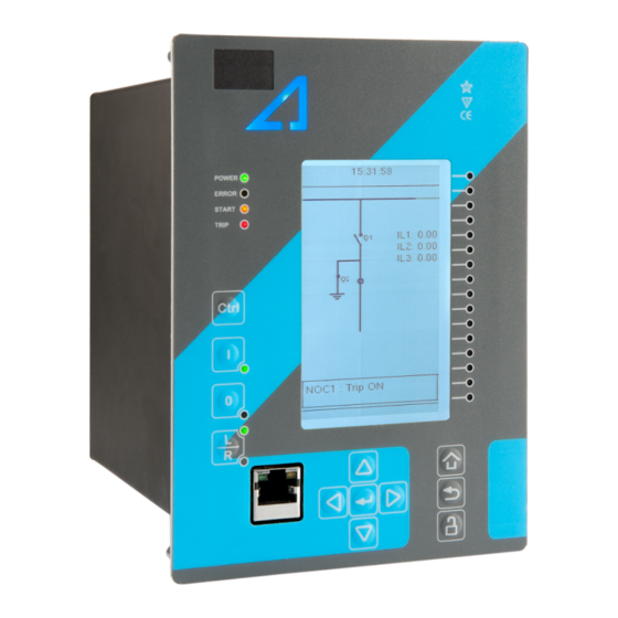
Version: 2.09 2 General The AQ-R215 railway protection device is a member of the AQ 200 product line. The hardware and software are modular: the hardware modules are assembled and configured according to the application's I/O requirements and the software determines the available functions. There are up to three (3) option card slots available for additional I/O or communication cards for more comprehensive monitoring and control applications. -
Page 14: Device User Int Vice User Interface Erface
5. Eight (8) buttons for device local programming: the four navigation arrows and the E E nt nter er button in the middle, as well as the Home Home, the Back Back and the password activation buttons. 6. One (1) RJ-45 Ethernet port for device configuration. © Arcteq Relays Ltd IM00034... -
Page 15: Mimic And Main Menu
LEDs you have set. The password activation button (with the padlock icon ) takes you to the password menu where you can enter the passwords for the various user levels (User, Operator, Configurator, and Super-user). © Arcteq Relays Ltd IM00034... -
Page 16: Navigation In The Main Configuration Menus
The General main menu is divided into two submenus: the Device info tab presents the information of the device, while the Function comments tab allows you to view all comments you have added to the functions. © Arcteq Relays Ltd IM00034... - Page 17 3 Device user interface A A Q Q -R215 -R215 3.3 General menu Instruction manual Version: 2.09 Figure. 3.3 - 4. General menu structure. Device info Figure. 3.3 - 5. Device info. © Arcteq Relays Ltd IM00034...
- Page 18 If set to 0 s, this feature is not in use. 0: - When activated, all LEDs are lit up. LEDs with LED test 0: - 1: Activated multiple possible colors blink each color. © Arcteq Relays Ltd IM00034...
- Page 19 Monitor profile Function comments Function comments displays notes of each function that has been activated in the Protection, Control and Monitoring menu. Function notes can be edited by the user. Figure. 3.3 - 6. Function comments. © Arcteq Relays Ltd IM00034...
-
Page 20: Protection Menu
The Protection main menu includes the Stage activation submenu as well as the submenus for all the various protection functions, categorized under the following modules: "Arc protection", "Current", "Voltage", "Frequency", "Sequence" and "Supporting" (see the image below). The available functions depend on the device type in use. © Arcteq Relays Ltd IM00034... - Page 21 For example, the I> (overcurrent) protection stage can be found in the "Current" module, whereas the U< (undervoltage) protection stage can be found in the "Voltage" module. Figure. 3.4 - 9. Submenus for Stage activation. © Arcteq Relays Ltd IM00034...
- Page 22 Figure. 3.4 - 10. Accessing the submenu of an individual activated stage. Each protection stage and supporting function has five sections in their stage submenus: "Info", "Settings", " Registers", "I/O" and "Events". Figure. 3.4 - 11. Info. © Arcteq Relays Ltd IM00034...
- Page 23 Voltage and current transformers nominal values can be set at Measurement → Transformers . • Delay type and operating time delay settings are described in detail in General properties of a protection function chapter. © Arcteq Relays Ltd IM00034...
- Page 24 Data included in the register depend on the protection function. You can clear the the operation register by choosing "Clear registers" → "Clear". "General event register" stores the event generated by the stage. These general event registers cannot be cleared. © Arcteq Relays Ltd IM00034...
- Page 25 "Blocking input control" allows you to block stages. The blocking can be done by using any of the following: • digital inputs • logical inputs or outputs • the START, TRIP or BLOCKED information of another protection stage • object status information. © Arcteq Relays Ltd IM00034...
-
Page 26: Control Menu
, for configuring the objects ( Objects) , for setting the various control functions ( Control functions) , and for configuring the inputs and outputs ( Device I/O) . The available control functions depend on the model of the device in use. © Arcteq Relays Ltd IM00034... - Page 27 • F F or orce se ce set t ting gr ting group change oup change: this setting allows the activation of a setting group at will (please note that Force SG change enable must be "Enabled"). © Arcteq Relays Ltd IM00034...
- Page 28 Each activated object is visible in the Objects submenu. By default all objects are disabled unless specifically activated in the Controls → Controls enabled submenu. Each active object has four sections in their submenus: "Settings", "Application control" ("App contr"), "Registers" and "Events". These are described in further detail below. © Arcteq Relays Ltd IM00034...
- Page 29 A request is considered to have failed when the object does not change its status as a result of that request. • C C lear sta lear statistics tistics: statistics can be cleared by choosing "Clear statistics" and then "Clear". © Arcteq Relays Ltd IM00034...
- Page 30 By default, the access level is set to "Configurator". • You can use digital inputs to control the object locally or remotely. Remote controlling via the bus is configured on the protocol level. © Arcteq Relays Ltd IM00034...
- Page 31 Object blocking is done in the "Blocking input control" subsection. It can be done by any of the following: digital inputs, logical inputs or outputs, object status information as well as stage starts, trips or blocks. Figure. 3.5 - 23. Registers section. © Arcteq Relays Ltd IM00034...
- Page 32 In the image series below, the user has activated three control functions. The user accesses the list of activated control stages through the "Control functions" module, and selects the control function for further inspection. Figure. 3.5 - 25. Control functions submenu. © Arcteq Relays Ltd IM00034...
- Page 33 While the function is activated and disabled in the Control → Controls enabled submenu, you can disable the function through the "Info" section (the [function name] mode at the top of the section). Figure. 3.5 - 27. Settings section. © Arcteq Relays Ltd IM00034...
- Page 34 Data included in the register depend on the control function. You can clear the the operation register by choosing "Clear registers" → "Clear". "General event register" stores the event generated by the stage. These general event registers cannot be cleared. © Arcteq Relays Ltd IM00034...
- Page 35 "Blocking input control" allows you to block stages. The blocking can be done by using any of the following: • digital inputs. • logical inputs or outputs. • the START, TRIP or BLOCKED information of another protection stage. • object status information. © Arcteq Relays Ltd IM00034...
- Page 36 Mimic Indicator", "Logic signals" and "GOOSE matrix". Please note that digital inputs, logic outputs, protection stage status signals (START, TRIP, BLOCKED, etc.) as well as object status signals can be connected to an output relay or to LEDs in the "Device I/O matrix" section. © Arcteq Relays Ltd IM00034...
- Page 37 "Event masks" subsection you can determine which events are masked –and therefore recorded into the event history– and which are not. Figure. 3.5 - 33. Digital outputs section. All settings related to digital outputs can be found in the "Digital outputs" section. © Arcteq Relays Ltd IM00034...
- Page 38 LED quick displays and the matrices. You can also modify the color of the LED ("LED color settings") between green and yellow; by default all LEDs are green. © Arcteq Relays Ltd IM00034...
- Page 39 These signals can be used in a variety of situations, such as for controlling the logic program, for function blocking, etc. You can name each switch and set the access level to determine who can control the switch. © Arcteq Relays Ltd IM00034...
- Page 40 Logical output signals can be used as the end result of a logic that has been built in the AQtivate 200 setting tool. The end result can then be connected to a digital output or a LED in the matrix, block functions and much more. © Arcteq Relays Ltd IM00034...
-
Page 41: Communication Menu
Communication → Connections submenu. As a standard, the devices support the following communication protocols: • NTP • IEC 61850 • Modbus/TCP • Modbus/RTU • IEC-103 • IEC -101/104 • SPA • DNP3 • ModbusIO. © Arcteq Relays Ltd IM00034... - Page 42 When communicating with a device via the front Ethernet port connection, the IP address is always 192.168.66.9. SERIAL COM1 & COM2 SERIAL COM1 & COM2 SERIAL COM1 and SERIAL COM2 are reserved for serial communication option cards. They have the same settings as the RS-485 port. © Arcteq Relays Ltd IM00034...
- Page 43 • DNP3: supports both serial and Ethernet communication. • ModbusIO: used for connecting external devices like ADAM RTD measurement units. NOTICE! TICE! Please refer to the "Communication" chapter for a more detailed text on the various communication options. © Arcteq Relays Ltd IM00034...
-
Page 44: Measurement Menu
Transformers menu is used for setting up the measurement settings of available current transformer modules or voltage transformer modules. Some unit types have more than one CT or VT module. Some unit types like AQ-S214 do not have current or voltage transformers at all. © Arcteq Relays Ltd IM00034... - Page 45 U4 channel can be set to work as residual voltage mode or "SS" (system set) mode, which can be used for synchrochecking, synchronizing and other uses. © Arcteq Relays Ltd IM00034...
- Page 46 Ref1, fRef2 and fRef3. With these parameters it is possible to set up three voltage or current channels to be used for frequency sampling. Parameter "f.meas in use" indicates which of the three channels are used for sampling if any. © Arcteq Relays Ltd IM00034...
- Page 47 (IL1, IL2, IL3) as well as the two residual currents (I01, I02); each component can be displayed as absolute or percentage values, and as primary or secondary amperages or in per-unit values. © Arcteq Relays Ltd IM00034...
- Page 48 • "Harmonics" displays harmonics up to the 31 harmonic for all four voltages (U1, U2, U3, U4); each component can be displayed as absolute or percentage values, and as primary or secondary voltages or in per-unit values. © Arcteq Relays Ltd IM00034...
- Page 49 "Energy measurements" displays the three-phase energy as well as the energies of the individual phases. Impedance calculations Figure. 3.7 - 50. Impedance calculations submenu. © Arcteq Relays Ltd IM00034...
-
Page 50: Monitoring Menu
( Disturbance REC ) and accessing the device diagnostics ( Device diagnostics ). The available monitoring functions depend on the type of the device in use. Figure. 3.8 - 52. Monitoring menu view. © Arcteq Relays Ltd IM00034... - Page 51 Configuring monitor functions is very similar to configuring protection and control stages. They, too, have the five sections that display information ("Info"), set the parameters ("Settings"), show the inputs and outputs ("I/O") and present the events and registers ("Events" and "Registers"). © Arcteq Relays Ltd IM00034...
- Page 52 • "Pretriggering time" can be selected between 0.1…15.0 s. • The device can record up to 20 (20) analog channels that can be selected from the twenty (20) available channels. Every measured current or voltage signal can be selected to be recorded. © Arcteq Relays Ltd IM00034...
-
Page 53: Configuring User Levels And Their Passwords
L L ock ock button in the device's HMI and set the desired passwords for the different user levels. NOTICE! TICE! Passwords can only be set locally in an HMI. © Arcteq Relays Ltd IM00034... - Page 54 As mentioned above, the access level of the different user levels is indicated by the number of stars. The required access level to change a parameter is indicated with a star (*) symbol if such is required. As a general rule the access levels are divided as follows: © Arcteq Relays Ltd IM00034...
- Page 55 • Super user: Can change any setting and can operate breakers and other equipment. NOTICE! TICE! Any user level with a password automatically locks itself after half an hour (30 minutes) of inactivity. © Arcteq Relays Ltd IM00034...
-
Page 56: Functions Unctions
Version: 2.09 4 Functions 4.1 Functions included in AQ-R215 The AQ-R215 railway protection device includes the following functions as well as the number of stages in those functions. Standard mode Table. 4.1 - 3. Protection functions of AQ-R215 in standard mode. - Page 57 PGS (1) PGx>/< Programmable stage ARC (1) IArc>/I0Arc> 50Arc/50NArc Arc fault protection (optional) Table. 4.1 - 4. Control functions of AQ-R215 in standard mode. Name ANSI Description Setting group selection Object control and monitoring (5 objects available) Indicator object monitoring...
- Page 58 Version: 2.09 Name ANSI Description Zero sequence recloser Programmable control switch mA output Milliampere output control Table. 4.1 - 5. Monitoring functions of AQ-R215 in standard mode. Name ANSI Description Current transformer supervision Voltage transformer supervision Disturbance recorder 21FL Fault locator...
-
Page 59: Measurements
4 Functions A A Q Q -R215 -R215 4.2 Measurements Instruction manual Version: 2.09 Table. 4.1 - 7. Control functions of AQ-R215 in railway mode. Name ANSI Description Setting group selection Object control and monitoring (5 objects available) Indicator object monitoring... - Page 60 For the measurements to be correct the user needs to ensure that the measurement signals are connected to the correct inputs, that the current direction is connected to the correct polarity, and that the scaling is set according to the nominal values of the current transformer. © Arcteq Relays Ltd IM00034...
- Page 61 CT in Input I02: T in Input I02: L L oad ( oad (nominal): nominal): • CT primary: 100 A • I0CT primary: 10 A 36 A • CT secondary: 5 A • I0CT secondary: 1 A © Arcteq Relays Ltd IM00034...
- Page 62 If the protected object's nominal current is chosen to be the basis for the per-unit scaling, the option "Object in p.u." is selected for the "Scale meas to In" setting (see the image below). Figure. 4.2.1 - 60. Setting the phase current transformer scalings to the protected object's nominal current. © Arcteq Relays Ltd IM00034...
- Page 63 The first of the two images shows how the measurements are displayed when the CT primary values are the basis for the scaling; the second shows them when the protected object's nominal current is the basis for the scaling. © Arcteq Relays Ltd IM00034...
- Page 64 Zero sequence CT scaling (ZCT scaling) is done when a zero sequence CT instead of a ring core CT is part of the measurement connection. In such a case the zero sequence CT should be connected to the I02 channel which has lower CT scaling ranges (see the image below). © Arcteq Relays Ltd IM00034...
- Page 65 The measured current amplitude does not match one of the measured Check the wiring connections between the injection device or the CTs and the device. phases./ The calculated I0 is measured even though it should not. © Arcteq Relays Ltd IM00034...
- Page 66 The following image presents the most common problems with phase polarity. Problems with phase polarity are easy to find because the vector diagram points towards the opposite polarity when a phase has been incorrectly connected. © Arcteq Relays Ltd IM00034...
- Page 67 If two phases are mixed together, the network rotation always follows the pattern IL1-IL3-IL2 and the measured negative sequence current is therefore always 1.00 (in. p.u.). © Arcteq Relays Ltd IM00034...
- Page 68 5 to connector 6, with the secondary currents' starpoint pointing towards the line. A feedback value; the calculated scaling factor that CT scaling is the ratio between the primary current and the factor P/S secondary current. © Arcteq Relays Ltd IM00034...
- Page 69 9 to connector A feedback value; the calculated scaling factor that is the scaling ratio between the primary current and the secondary factor P/S current. Measurements The following measurements are available in the measured current channels. © Arcteq Relays Ltd IM00034...
- Page 70 TRMS Sec") Table. 4.2.1 - 16. Phase angle measurements. Name Unit Range Step Description Phase angle The phase angle measurement from each of the three phase 0.00…360.00 0.01 ("Pha.angle current inputs. ILx") © Arcteq Relays Ltd IM00034...
- Page 71 0.00…300.00 0.01 calculated current channel I0. ("Sec.calc.I0") Secondary residual The secondary TRMS current (inc. harmonics up to 31 current I0x TRMS 0.00…300.00 0.01 measurement from the secondary residual current channel (Res.curr.I0x TRMS I01 or I02. Sec") © Arcteq Relays Ltd IM00034...
- Page 72 Secondary positive sequence current The secondary measurement from the calculated 0.00…300.00 0.01 ("Sec.Positive sequence positive sequence current. curr.") Secondary negative sequence current The secondary measurement from the calculated 0.00…300.00 0.01 ("Sec.Negative sequence negative sequence current. curr") © Arcteq Relays Ltd IM00034...
- Page 73 Displays the selected harmonic from the current input ILx or 0.01 ...31 000.00 I0x. harmonic) Ixx Amplitude % 0.000...100.000 0.001 Amplitude ratio THD voltage. Recognized by IEC. Ixx Power THD % 0.000...100.000 0.001 Power ratio THD voltage. Recognized by the IEEE. © Arcteq Relays Ltd IM00034...
-
Page 74: Voltage Measurement And Scaling
VT ratings. In the figure below, three line-to-neutral voltages are connected along with the zero sequence voltage; therefore, the 3LN+U4 mode must be selected and the U4 channel must be set as U0. Other possible connections are presented later in this chapter. © Arcteq Relays Ltd IM00034... - Page 75 ( Protection → Voltage → [protection stage menu] → INFO ; see the image below). The number of available protection functions depends on the device type. Figure. 4.2.2 - 70. Selecting the measured magnitude. © Arcteq Relays Ltd IM00034...
- Page 76 • 2LL+U3+U4 (two line-to-line voltages and the U3 and the U4 channels can be used for synchrochecking, zero sequence voltage, or for both) The 3LN+U0 is the most common voltage measurement mode. See below for example connections of voltage line-to-line measurement (3LL on the left, 2LL on the right). © Arcteq Relays Ltd IM00034...
- Page 77 In the image below is an example of 2LL+U0+SS, that is, two line-to-line measurements with the zero sequence voltage and voltage from side 2 for Synchrocheck. Since U0 is available, line-to-neutral voltages can be calculated. Figure. 4.2.2 - 73. 2LL+U0+SS settings and connections. © Arcteq Relays Ltd IM00034...
- Page 78 The measured voltage amplitude does not match one of the measured phases./ Check the wiring connections between the injection device or the VTs and the device. The calculated U0 is measured even though it should not. © Arcteq Relays Ltd IM00034...
- Page 79 "U4 mode U0 or SS" has been set to 2: Open the "U0" mode. delta Voltage 0: Disabled Activates the voltage memory. The "Voltage memory" memory 1: Activated Disabled chapter describes the function in more detail. © Arcteq Relays Ltd IM00034...
- Page 80 VT scaling A feedback value; the scaling factor for the primary factor p.u. Pri voltage's per-unit value. VT scaling A feedback value; the scaling factor for the factor p.u. Sec secondary voltage's per-unit value. © Arcteq Relays Ltd IM00034...
- Page 81 The secondary RMS voltage measurement from each of the voltage Ux 0.00…500.00 0.01 voltage channels. ("Ux Volt sec") Secondary voltage Ux 0.00…500.00 0.01 The secondary TRMS voltage (inc. harmonics up to 31 TRMS measurement from each of the voltage channels. ("UxVolt TRMS sec") © Arcteq Relays Ltd IM00034...
- Page 82 ("Pos.seq.Volt.sec") Secondary negative 0.00…4 The secondary measurement from the calculated sequence voltage 0.01 800.00 negative sequence voltage. ("Neg.seq.Volt.sec") Secondary zero sequence 0.00…4 The secondary measurement from the calculated zero voltage 0.01 800.00 sequence voltage. ("Zero.seq.Volt.sec") © Arcteq Relays Ltd IM00034...
- Page 83 UL1 mag") System voltage magnitude 0.00…1 The primary RMS line-to-neutral UL2 voltage (measured or calculated). You 0.01 can also select the row where the unit for this is kV. ("System 000.00 volt UL2 mag") © Arcteq Relays Ltd IM00034...
- Page 84 UL23 0.00…360.00 0.01 The primary line-to-line angle UL23 (measured or calculated). ("System volt UL23 ang") System voltage angle UL31 0.00…360.00 0.01 The primary line-to-line angle UL23 (measured or calculated). ("System volt UL31 ang") © Arcteq Relays Ltd IM00034...
- Page 85 Defines how the harmonics are displayed: in p.u. values, as 1: Primary V display primary voltage values, or as secondary voltage values. 2: Secondary V Maximum 0.00…100 Displays the maximum harmonics value of the selected harmonics value 0.01 000.00 voltage input Ux. ("UxMaxH") © Arcteq Relays Ltd IM00034...
-
Page 86: Voltage Memory
2. At least one phase current must be above the set value for the "Measured current condition 3I>" parameter. This setting limit is optional. Figure. 4.2.3 - 76. Distance protection characteristics and directional overcurrent. © Arcteq Relays Ltd IM00034... - Page 87 Table. 4.2.3 - 38. Measurement inputs of the voltage memory function. Signal Description Time base IL1RMS RMS measurement of phase L1 (A) current IL2RMS RMS measurement of phase L2 (B) current IL3RMS RMS measurement of phase L3 (C) current RMS measurement of voltage U © Arcteq Relays Ltd IM00034...
- Page 88 When the "Forced CT f tracking" parameter is activated and voltages are gone, the frequency from the selected current-based reference channel 3 (the current from IL3) is used for current sampling. This eliminates any possible measurement errors in the fixed frequency mode. Figure. 4.2.3 - 78. Frequency reference channels. © Arcteq Relays Ltd IM00034...
-
Page 89: Power And Energy Calculation
The following equations apply for power calculations with the line-to-neutral mode and the line- to-line voltage mode (with U0 connected and measured): © Arcteq Relays Ltd IM00034... - Page 90 The direction of reactive power is divided into four quadrants. Reactive power may be inductive or capacitive on both forward and reverse directions. Reactive power quadrant can be indicated with Tan (φ) (tangent phi), which is calculated according the following formula: © Arcteq Relays Ltd IM00034...
- Page 91 (i.e. wiring errors, wrong measurement modes, faulty frequency settings, etc.). Settings Table. 4.2.4 - 40. Power and energy measurement settings Name Range Step Default Description 3ph active 0: Disabled Enables/disables the active energy energy 1: Enabled Disabled measurement. measurement © Arcteq Relays Ltd IM00034...
- Page 92 Reset energy calculators Resets the memory of the indivisual phase 0: - (per phase) 0: - energy calculator. Goes automatically back to 1: Reset ("Reset E per the "-" state after the reset is finished. phase") © Arcteq Relays Ltd IM00034...
- Page 93 Table. 4.2.4 - 43. Three-phase power calculations. Name Unit Range Step Description The total three-phase apparent power in kilo-volt- 3PH Apparent power (S) 0.01 -1x10 …1x10 ampere 3PH Active power (P) 0.01 The total three-phase active power in kilowatts -1x10 …1x10 © Arcteq Relays Ltd IM00034...
- Page 94 0.01 The total amount of imported active energy. (kWh or MWh) 995 904.00 -999 999 995 Active Energy (P) Export/ The sum of imported and exported active 904.00…999 999 0.01 Import balance (kWh or MWh) energy. 995 904.00 © Arcteq Relays Ltd IM00034...
- Page 95 The exported reactive energy of the phase while 0.01 -1x10 …1x10 (kVarh or MVarh) active energy is imported. Imported (Q) while Import (P) Lx The imported reactive energy of the phase while 0.01 -1x10 …1x10 (kVarh or MVarh) active energy is imported. © Arcteq Relays Ltd IM00034...
- Page 96 L2 Tan an -0.83 L3 T L3 Tan an 0.11 3PH T H Tan an 0.00 L1 Cos L1 Cos 0.71 L2 Cos L2 Cos 0.77 L3 Cos L3 Cos 0.99 3PH Cos H Cos 0.87 © Arcteq Relays Ltd IM00034...
-
Page 97: Frequency Tracking And Scaling
The benefit of frequency tracking is that the measurements are within a pre-defined accuracy range even when the fundamental frequency of the power system changes. Frequency independent current and voltage measurement accuracy is achieved with algorithms specified in patent US 10,809,287. © Arcteq Relays Ltd IM00034... - Page 98 FFT calculation always has a whole power cycle in the buffer. The measurement accuracy is further improved by Arcteq's patented calibration algorithms that calibrate the analog channels against eight (8) system frequency points for both magnitude and angle.
- Page 99 The second reference source for frequency 2: CT2IL2 1: CT1IL2 reference 2 tracking. 3: VT1U2 4: VT2U2 0: None 1: CT1IL3 Frequency 2: CT2IL3 1: CT1IL3 The third reference source for frequency tracking. reference 3 3: VT1U3 4: VT2U3 © Arcteq Relays Ltd IM00034...
- Page 100 Alg f avg 0.000…75.000Hz 0.001Hz - tracked frequencies and U4 voltage channel samples. 0: One f measured System 1: Two f Displays the amount of frequencies that are measured measured measured. frequency 2: Three f measured © Arcteq Relays Ltd IM00034...
-
Page 101: General Menu
The order code identification of the unit. System phase rotating order at The selected system phase rotating order. Can be changed with parameter the moment "System phase rotating order". UTC time The UTC time value which the device's clock uses. © Arcteq Relays Ltd IM00034... - Page 102 When a reset command is given, the parameter 1: Reset automatically returns back to "-". 0: Disabled Enables the measurement recorder tool, further Measurement recorder 0: Disabled 1: Enabled configured in Tools → Misc → Measurement recorder. © Arcteq Relays Ltd IM00034...
-
Page 103: Protection Functions
4.4.1 General properties of a protection function The following flowchart describes the basic structure of any protection function. The basic structure is composed of analog measurement values being compared to the pick-up values and operating time characteristics. © Arcteq Relays Ltd IM00034... - Page 104 4 Functions Instruction manual 4.4 Protection functions Version: 2.09 The protection function is run in a completely digital environment with a protection CPU microprocessor which also processes the analog signals transformed into the digital form. © Arcteq Relays Ltd IM00034...
- Page 105 Figure. 4.4.1 - 83. Pick up and reset. The pick-up activation of the function is not directly equal to the START signal generation of the function. The START signal is allowed if a blocking condition is not active. © Arcteq Relays Ltd IM00034...
- Page 106 (independent time characteristics). • Inverse definite minimum time (IDMT): activates the trip signal after a time which is in relation to the set pick-up value X and the measured value X (dependent time characteristics). © Arcteq Relays Ltd IM00034...
- Page 107 Selects whether the delay curve series for an IDMT operation follows either IEC or IEEE/ANSI standard Delay curve 0: IEC defined characteristics. 0: IEC series 1: IEEE This setting is active and visible when the "Delay type" parameter is set to "IDMT". © Arcteq Relays Ltd IM00034...
- Page 108 "Param". Defines the Constant C for IEEE characteristics. This setting is active and visible when the "Delay type" 0.0000…250.0000 0.0001 0.0200 parameter is set to "IDMT" and the "Delay characteristic" parameter is set to "Param". © Arcteq Relays Ltd IM00034...
- Page 109 = Operating delay (s) t = Operating delay (s) k = Time dial setting k = Time dial setting = Measured maximum current = Measured maximum current = Pick-up setting = Pick-up setting © Arcteq Relays Ltd IM00034...
- Page 110 1: Yes even if the pick-up element is reset. release time The behavior of the stages with different release time configurations are presented in the figures below. Figure. 4.4.1 - 87. No delayed pick-up release. © Arcteq Relays Ltd IM00034...
- Page 111 4.4 Protection functions Instruction manual Version: 2.09 Figure. 4.4.1 - 88. Delayed pick-up release, delay counter is reset at signal drop-off. Figure. 4.4.1 - 89. Delayed pick-up release, delay counter value is held during the release time. © Arcteq Relays Ltd IM00034...
-
Page 112: Railway Protection Module
Stage Forcing after testing has ended. 4.4.2 Railway protection module The railway protection module is a function specific to the AQ-R215 protection relay. It is capable of handling current and voltage measurements in either railroad frequencies (16.67 Hz) or standard three-phase system frequencies (50/60 Hz). - Page 113 -360.00...360.00deg 0.01deg (ff) Hz) voltages. U1–U2 angle -360.00...360.00deg 0.01deg The angle between U and U harmonic (50 Hz) voltages. (3H) U1–U3 angle -360.00...360.00deg 0.01deg The angle between U and U harmonic (50 Hz) voltages. (3H) © Arcteq Relays Ltd IM00034...
-
Page 114: Railway Non-Directional Overcurrent Protection (I>; 50/51)
START and TRIP events simultaneously with an equivalent time stamp. The time stamp resolution is 1 ms. The function also provides a resettable cumulative counter for the START, TRIP and BLOCKED events. The following figure presents a simplified function block diagram of the railway non-directional overcurrent function. © Arcteq Relays Ltd IM00034... - Page 115 Table. 4.4.2.1 - 58. General settings of the function. Name Range Default Description Setting control 1: Disabled Activating this parameter permits changing the pick-up level of from comm 1: Disabled 2: Allowed the protection stage via SCADA. © Arcteq Relays Ltd IM00034...
- Page 116 Pick-up setting 0.10…50.00×I 0.01×I 1.20×I The pick-up activation of the function is not directly equal to the START signal generation of the function. The START signal is allowed if the blocking condition is not active. © Arcteq Relays Ltd IM00034...
- Page 117 START signal is generated and the function proceeds to the time characteristics calculation. Table. 4.4.2.1 - 61. Internal inrush harmonic blocking settings. Name Description Range Step Default Inrush harmonic blocking (internal- 0: No harmonic blocking 0: No only trip) 1: Yes enable/disable © Arcteq Relays Ltd IM00034...
- Page 118 NOC1 Start OFF NOC1 Trip ON NOC1 Trip OFF NOC1 Block ON NOC1 Block OFF NOC1 Phase A Start ON NOC1 Phase A Start OFF NOC1 Phase B Start ON NOC1 Phase B Start OFF © Arcteq Relays Ltd IM00034...
- Page 119 NOC2 Phase B Trip ON NOC2 Phase B Trip OFF NOC2 Phase C Trip ON NOC2 Phase C Trip OFF NOC3 Start ON NOC3 Start OFF NOC3 Trip ON NOC3 Trip OFF NOC3 Block ON © Arcteq Relays Ltd IM00034...
- Page 120 NOC4 Phase C Start OFF NOC4 Phase A Trip ON NOC4 Phase A Trip OFF NOC4 Phase B Trip ON NOC4 Phase B Trip OFF NOC4 Phase C Trip ON NOC4 Phase C Trip OFF © Arcteq Relays Ltd IM00034...
-
Page 121: Railway Directional Overcurrent Protection (Idrw>; 67)
The basic design of the protection function is the three-pole operation. The inputs for the function are the following: • operating mode selections • setting parameters • digital inputs and logic signals • measured and pre-processed current magnitudes. © Arcteq Relays Ltd IM00034... - Page 122 Table. 4.4.2.2 - 64. Measurement inputs of the Idir> function. Signal Description Time base IL1RMS RMS measurement of phase L1 (A) current IL2RMS RMS measurement of phase L2 (B) current IL3RMS RMS measurement of phase L3 (C) current I01RMS RMS measurement of I01 current © Arcteq Relays Ltd IM00034...
- Page 123 (50 Hz) of the railway network is used by the function. frequency harmonic frequency 1: IL1 Current input 2: IL2 channel 3: IL3 1: IL1 Assigns a current measurement channel to the protection stage. select 4: I01 5: I02 © Arcteq Relays Ltd IM00034...
- Page 124 Directional sector mode is use. sector +/- center The pick-up activation of the function is not directly equal to the START signal generation of the function. The START signal is allowed if the blocking condition is not active. © Arcteq Relays Ltd IM00034...
- Page 125 The current angle is compared to voltage angle, and if the fault is in the correct direction it is possible to perform a trip when the amplitude of the current and the voltage increases above the pick-up limit. © Arcteq Relays Ltd IM00034...
- Page 126 Time When the function has detected a fault and counts down time remaining -1800.000...1800.00s 0.005s towards a trip, this displays how much time is left before tripping to trip occurs. © Arcteq Relays Ltd IM00034...
- Page 127 This function supports instant operation, definite time delay (DT) and inverse definite minimum time delay (IDMT). For detailed information on these delay types refer to the chapter "General properties of a protection function" and its section "Operating time characteristics for trip and reset". © Arcteq Relays Ltd IM00034...
- Page 128 Start OFF ROC3 Trip ON ROC3 Trip OFF ROC3 Block ON ROC3 Block OFF ROC4 Start ON ROC4 Start OFF ROC4 Trip ON ROC4 Trip OFF ROC4 Block ON ROC4 Block OFF ROC5 Start ON © Arcteq Relays Ltd IM00034...
- Page 129 ON event process data for START, TRIP or BLOCKED. The table below presents the structure of the function's register content. Table. 4.4.2.2 - 69. Register content. Register Description Date and time dd.mm.yyyy hh:mm:ss.mss Event Event name Fault type L1-E...L1-L2-L3 © Arcteq Relays Ltd IM00034...
-
Page 130: Railway Voltage Protection (Urw>/<; 27/59)
• block signal check • time delay characteristics • output processing. The inputs for the function are the following: • operating mode selections • setting parameters • digital inputs and logic signals • measured and pre-processed voltage magnitudes. © Arcteq Relays Ltd IM00034... - Page 131 The reset ratio of 103 % in undervoltage applications is built into the function and is always relative to the U value. When the measured voltage goes above or below the U value it triggers the pick-up operation of the function. © Arcteq Relays Ltd IM00034...
- Page 132 The relay's Info page displays useful, real-time information on the state of the protection function. It is accessed either through the relay's HMI display, or through the setting tool software when it is connected to the relay and its Live Edit mode is active. © Arcteq Relays Ltd IM00034...
- Page 133 • Definite time operation (DT): gives the TRIP signal after a user-defined time delay regardless of the measured or calculated voltage as long as the voltage is above the U value and thus the pick- up element is active (independent time characteristics). © Arcteq Relays Ltd IM00034...
- Page 134 Resetting characteristics selection either as time-delayed or 1: No pick-up 2: Yes as instant after the pick-up element is released. If activated, 2: Yes release the START signal is reset after a set release time delay. © Arcteq Relays Ltd IM00034...
- Page 135 Start OFF ROV1 Trip ON ROV1 Trip OFF ROV1 Block ON ROV1 Block OFF ROV2 Start ON ROV2 Start OFF ROV2 Trip ON ROV2 Trip OFF ROV2 Block ON ROV2 Block OFF ROV3 Start ON © Arcteq Relays Ltd IM00034...
-
Page 136: Non-Directional Overcurrent Protection (I>; 50/51)
IEC and ANSI standard time delays as well as custom parameters. The function includes CT saturation checking which allows the function to start and operate accurately during CT saturation. The operational logic consists of the following: © Arcteq Relays Ltd IM00034... - Page 137 The user can select the monitored magnitude to be equal either to RMS values, to TRMS values from the whole harmonic specter of 32 components, or to peak-to-peak values. A -20ms averaged value of the selected magnitude is used for pre-fault data registering. © Arcteq Relays Ltd IM00034...
- Page 138 Table. 4.4.3 - 79. General settings of the function. Name Range Default Description Disabled Setting control Activating this parameter allows changing the pick-up level of the from comm bus Disabled protection stage via SCADA. Allowed © Arcteq Relays Ltd IM00034...
- Page 139 0.10…50.00×I 0.01×I 1.20×I Pick-up setting The pick-up activation of the function is not directly equal to the START signal generation of the function. The START signal is allowed if the blocking condition is not active. © Arcteq Relays Ltd IM00034...
- Page 140 START signal is generated and the function proceeds to the time characteristics calculation. Table. 4.4.3 - 82. Internal inrush harmonic blocking settings. Name Range Step Default Description Inrush harmonic blocking 0: No Enables and disables the 2 0: No (internal-only trip) 1: Yes harmonic blocking. © Arcteq Relays Ltd IM00034...
- Page 141 Block ON NOC1 Block OFF NOC1 Phase A Start ON NOC1 Phase A Start OFF NOC1 Phase B Start ON NOC1 Phase B Start OFF NOC1 Phase C Start ON NOC1 Phase C Start OFF © Arcteq Relays Ltd IM00034...
- Page 142 Phase B Trip OFF NOC2 Phase C Trip ON NOC2 Phase C Trip OFF NOC3 Start ON NOC3 Start OFF NOC3 Trip ON NOC3 Trip OFF NOC3 Block ON NOC3 Block OFF NOC3 Phase A Start ON © Arcteq Relays Ltd IM00034...
- Page 143 NOC4 Phase C Start OFF NOC4 Phase A Trip ON NOC4 Phase A Trip OFF NOC4 Phase B Trip ON NOC4 Phase B Trip OFF NOC4 Phase C Trip ON NOC4 Phase C Trip OFF © Arcteq Relays Ltd IM00034...
-
Page 144: Non-Directional Earth Fault Protection (I0>; 50N/51N)
(3) output signals. In the instant operating mode the function outputs START and TRIP events simultaneously with an equivalent time stamp. The time stamp resolution is 1 ms. The function also provides a resettable cumulative counter for the START, TRIP and BLOCKED events. © Arcteq Relays Ltd IM00034... - Page 145 START or TRIP event. General settings The following general settings define the general behavior of the function. These settings are static i.e. it is not possible to change them by editing the setting group. © Arcteq Relays Ltd IM00034...
- Page 146 Live Edit mode is active. Table. 4.4.4 - 88. Information displayed by the function. Name Range Step Description 0: Normal I0> 1: Start Displays status of the protection function. condition 2: Trip 3: Blocked © Arcteq Relays Ltd IM00034...
- Page 147 The variables the user can set are binary signals from the system. The blocking signal needs to reach the device minimum of 5 ms before the set operating delay has passed in order for the blocking to activate in time. © Arcteq Relays Ltd IM00034...
- Page 148 Trip OFF NEF2 Block ON NEF2 Block OFF NEF3 Start ON NEF3 Start OFF NEF3 Trip ON NEF3 Trip OFF NEF3 Block ON NEF3 Block OFF NEF4 Start ON NEF4 Start OFF NEF4 Trip ON © Arcteq Relays Ltd IM00034...
-
Page 149: Directional Overcurrent Protection (Idir>; 67)
• block signal check • time delay characteristics • output processing. The basic design of the protection function is the three-pole operation. The inputs for the function are the following: • operating mode selections • setting parameters © Arcteq Relays Ltd IM00034... - Page 150 Table. 4.4.5 - 92. Measurement inputs of the Idir> function. Signal Description Time base IL1RMS RMS measurement of phase L1 (A) current IL2RMS RMS measurement of phase L2 (B) current IL3RMS RMS measurement of phase L3 (C) current © Arcteq Relays Ltd IM00034...
- Page 151 I value. The setting value is common for all measured phases, and when the I exceeds the I value (in single, dual or all phases) it triggers the pick-up operation of the function. © Arcteq Relays Ltd IM00034...
- Page 152 . The angle of the positive sequence current I is compared to U angle, and if the fault is in the correct direction, it is possible to perform a trip when the amplitude of I or I increases above the pick-up limit. © Arcteq Relays Ltd IM00034...
- Page 153 In a short- circuit the angle comes from impedance calculation. Figure. 4.4.5 - 99. Operation sector area when the sector center has been set to -45 degrees. © Arcteq Relays Ltd IM00034...
- Page 154 -1800.000...1800.00s 0.005s towards a trip, this displays how much time is left before to trip tripping occurs. meas The ratio between the highest measured phase current and the 0.00...1250.00I 0.01I at the pick-up value. moment © Arcteq Relays Ltd IM00034...
- Page 155 The events triggered by the function are recorded with a time stamp and with process data values. Table. 4.4.5 - 97. Event messages. Event block name Event names DOC1 Start ON DOC1 Start OFF DOC1 Trip ON DOC1 Trip OFF © Arcteq Relays Ltd IM00034...
- Page 156 Trip ON DOC3 Trip OFF DOC3 Block ON DOC3 Block OFF DOC3 No voltage, Blocking ON DOC3 Voltage measurable, Blocking OFF DOC3 Measuring live angle ON DOC3 Measuring live angle OFF DOC3 Using voltmem ON © Arcteq Relays Ltd IM00034...
- Page 157 Event Event name Fault type L1-E...L1-L2-L3 Pre-trigger current Start/Trip -20ms current Fault current Start/Trip current Pre-fault current Start -200ms averages Trip time remaining 0s...1800s Used SG Setting group 1...8 active Operating angle 0...250° © Arcteq Relays Ltd IM00034...
-
Page 158: Directional Earth Fault Protection (I0Dir>; 67N/32N)
START and TRIP events simultaneously with an equivalent time stamp. The time stamp resolution is 1 ms. The function also provides a cumulative counter for the START, TRIP and BLOCKED events. The following figure presents a simplified function block diagram of the directional earth fault function. © Arcteq Relays Ltd IM00034... - Page 159 The selection of the used AI channel is made with a setting parameter. In all possible input channel variations the pre-fault condition is presented with a 20 ms averaged history value from -20 ms from a START or TRIP event. © Arcteq Relays Ltd IM00034...
- Page 160 (or U0 ) value. When the I exceeds the I0 value it triggers the pick-up operation of the function. Table. 4.4.6 - 101. Pick-up settings. Name Description Range Step Default Pick-up setting 0.005…40.00×I 0.001×I 1.20×I © Arcteq Relays Ltd IM00034...
- Page 161 I0 angle blinder (Petersen coil earthed) -90.0…0.0° 0.1° -90° The pick-up activation of the function is not directly equal to the START signal generation of the function. The START signal is allowed if the blocking condition is not active. © Arcteq Relays Ltd IM00034...
- Page 162 Each outgoing feeder produces capacitance according to the zero sequence capacitive reactance of the line (ohms per kilometer). It is normal that in cable networks fault currents are higher than in overhead lines. © Arcteq Relays Ltd IM00034...
- Page 163 In emergency situations a line with an earth fault can be used for a specific time. Figure. 4.4.6 - 103. Angle tracking of I0dir> function (Petersen coil earthed network model). © Arcteq Relays Ltd IM00034...
- Page 164 This resistance includes the amplitude of the fault current. In undercompensated or overcompensated situations the resistive component does not change during the fault; therefore, selective tripping is ensured even when the network is slightly undercompensated or overcompensated. © Arcteq Relays Ltd IM00034...
- Page 165 Directly earthed or small impedance network schemes are normal in transmission, distribution and industry. The phase angle setting of the tripping area is adjustable as is the base direction of the area (angle offset). © Arcteq Relays Ltd IM00034...
- Page 166 CT errors. For all these reasons, Arcteq has developed an improved alternative to these traditional directional earth fault protections.
- Page 167 No extra parameterization is required compared to the traditional method. The multi- criteria algorithm can be tested with COMTRADE files supplied by Arcteq. The function requires a connection of three-phase currents, residual current and residual voltage to operate correctly.
- Page 168 START signal is generated and the function proceeds to the time characteristics calculation. Table. 4.4.6 - 103. Internal inrush harmonic blocking settings. Name Description Range Step Default Inrush harmonic blocking 0: No Enables and disables the 2 0: No (internal-only trip) 1: Yes harmonic blocking. © Arcteq Relays Ltd IM00034...
- Page 169 Trip ON DEF1 Trip OFF DEF1 Block ON DEF1 Block OFF DEF1 I0Cosfi Start ON DEF1 I0Cosfi Start OFF DEF1 I0Sinfi Start ON DEF1 I0Sinfi Start OFF DEF1 I0Cosfi Trip ON DEF1 I0Cosfi Trip OFF © Arcteq Relays Ltd IM00034...
- Page 170 DEF3 I0Cosfi Start ON DEF3 I0Cosfi Start OFF DEF3 I0Sinfi Start ON DEF3 I0Sinfi Start OFF DEF3 I0Cosfi Trip ON DEF3 I0Cosfi Trip OFF DEF3 I0Sinfi Trip ON DEF3 I0Sinfi Trip OFF DEF4 Start ON © Arcteq Relays Ltd IM00034...
- Page 171 Fault U Start/Trip voltage (percentage of nominal) Fault U Start/Trip voltage (in Volts) fault angle 0...360° Trip time remaining 0 ms...1800s Used SG Setting group 1...8 active Network GND Unearthed, Petersen coil earthed, Earthed network © Arcteq Relays Ltd IM00034...
-
Page 172: Intermittent Earth Fault Protection (I0Int>; 67Nt)
Handling these unique characteristics requires a completely different set of tools than what traditional directional earth fault protection can offer. The following figures present three intermittent earth fault situations experienced by relays in a substation.. © Arcteq Relays Ltd IM00034... - Page 173 A A Q Q -R215 -R215 4.4 Protection functions Instruction manual Version: 2.09 Figure. 4.4.7 - 107. An intermittent earth fault in a medium size network tuned close to resonance, as seen by a faulty feeder relay. © Arcteq Relays Ltd IM00034...
- Page 174 A A Q Q -R215 -R215 4 Functions Instruction manual 4.4 Protection functions Version: 2.09 Figure. 4.4.7 - 108. An intermittent earth fault in a network tuned close to resonance, as seen by a healthy feeder relay. © Arcteq Relays Ltd IM00034...
- Page 175 4 Functions A A Q Q -R215 -R215 4.4 Protection functions Instruction manual Version: 2.09 Figure. 4.4.7 - 109. An intermittent earth fault in an undercompensated medium size network, as seen by a faulty feeder relay. © Arcteq Relays Ltd IM00034...
- Page 176 DELTAI0 and the residual voltage UC difference DELTAU0. A negative admittance-delta is classified as forward (FWD). A transient-type earth fault is detected in the branch line with the aid of at least one forward (FWD) spike during a selected time (FWDreset). © Arcteq Relays Ltd IM00034...
- Page 177 General setting parameter values are presented below. Setting parameter Value U0 Detect spike > 60 % 0.5 x I0 I0 Detect spike > FWD reset time 0.250 s REV reset time 0.250 s © Arcteq Relays Ltd IM00034...
- Page 178 Force the status of the function. Visible only when Enable stage I0Int> force status to StartFWD Normal forcing parameter is enabled in General menu. StartREV 4: Trip Input 1: I01 1: I01 Defines which measured residual current is used by the function. selection 2: I02 © Arcteq Relays Ltd IM00034...
- Page 179 0.000...1800.000s 0.005s towards a trip, this displays how much time is left before tripping to trip occurs. Spikes Displays how many spikes need to be detected before tripping can remaining 0...4294967295 occur. to trip > © Arcteq Relays Ltd IM00034...
- Page 180 Spikes to exceeded. If the set operating time is reached but the 1...50 trip > calculated spike number is below this, the setting function releases without a trip when the FWD reset time has elapsed. © Arcteq Relays Ltd IM00034...
- Page 181 1...8 hh:mm:ss.mss name forward start forward reverse start reverse forward operating in this fault. (faulty) in this fault. (healthy) spikes. If 0 time. feeder spikes. feeder spikes spikes, it trips. © Arcteq Relays Ltd IM00034...
-
Page 182: Negative Sequence Overcurrent/ Phase Current Reversal/ Current Unbalance Protection (I2>; 46/46R/46L)
START and TRIP events simultaneously with an equivalent time stamp. The time stamp resolution is 1 ms. The function also provides a resettable cumulative counter for the START, TRIP and BLOCKED events. The following figure presents a simplified function block diagram of the current unbalance function. © Arcteq Relays Ltd IM00034... - Page 183 Phase L3 (C) measured RMS current 5 ms General settings The following general settings define the general behavior of the function. These settings are static i.e. it is not possible to change them by editing the setting group. © Arcteq Relays Ltd IM00034...
- Page 184 If the blocking signal is not activated when the pick-up element activates, a START signal is generated and the function proceeds to the time characteristics calculation. © Arcteq Relays Ltd IM00034...
- Page 185 Unique to the current unbalance protection is the availability of the “Curve2” delay which follows the formula below: • t = Operating time • I = Calculated negative sequence 2meas • k = Constant k value (user settable delay multiplier) • I = Pick-up setting of the function © Arcteq Relays Ltd IM00034...
- Page 186 The triggering event of the function (START, TRIP or BLOCKED) is recorded with a time stamp and with process data values. Table. 4.4.8 - 117. Event messages. Event block name Event names CUB1 Start ON CUB1 Start OFF © Arcteq Relays Ltd IM00034...
- Page 187 Trip time Date and time Event Used SG current current current currents remaining Start/Trip Start I1, I2, IZ Setting dd.mm.yyyy Event Start/Trip -20ms -200ms mag. and group 1...8 hh:mm:ss.mss name current ms...1800s current current ang. active © Arcteq Relays Ltd IM00034...
-
Page 188: Harmonic Overcurrent Protection (Ih>; 50H/51H/68H)
START and TRIP events simultaneously with an equivalent time stamp. The time stamp resolution is 1 ms. The function also provides a resettable cumulative counter for the START, TRIP and BLOCKED events. The following figure presents a simplified function block diagram of the non-directional harmonic overcurrent function. © Arcteq Relays Ltd IM00034... - Page 189 The magnitudes (RMS) of phase L1 (A) current components: - Fundamental harmonic harmonic harmonic harmonic harmonic IL1FFT 5 ms harmonic harmonic - 11 harmonic - 13 harmonic - 15 harmonic - 17 harmonic - 19 harmonic. © Arcteq Relays Ltd IM00034...
- Page 190 The magnitudes (RMS) of residual I0 current components: - Fundamental harmonic harmonic harmonic harmonic harmonic I01FFT 5 ms harmonic harmonic - 11 harmonic - 13 harmonic - 15 harmonic - 17 harmonic - 19 harmonic. © Arcteq Relays Ltd IM00034...
- Page 191 Table. 4.4.9 - 120. Operating mode selection settings. Name Range Default Description Normal Ih> force 1: Start Force the status of the function. Visible only when Enable stage status to 2: Trip Normal forcing parameter is enabled in General menu. Blocked © Arcteq Relays Ltd IM00034...
- Page 192 (in single, dual or all phases) it triggers the pick-up operation of the function. Table. 4.4.9 - 121. Pick-up settings. Name Range Step Default Description Pick-up setting 0.05…2.00×I 0.01×I 0.20×I (per unit monitoring) Pick-up setting Ih/IL 5.00…200.00% 0.01% 20.00% (percentage monitoring) © Arcteq Relays Ltd IM00034...
- Page 193 This function supports definite time delay (DT) and inverse definite minimum time delay (IDMT). For detailed information on these delay types please refer to the chapter "General properties of a protection function" and its section "Operating time characteristics for trip and reset". © Arcteq Relays Ltd IM00034...
- Page 194 Start ON HOC3 Start OFF HOC3 Trip ON HOC3 Trip OFF HOC3 Block ON HOC3 Block OFF HOC4 Start ON HOC4 Start OFF HOC4 Trip ON HOC4 Trip OFF HOC4 Block ON HOC4 Block OFF © Arcteq Relays Ltd IM00034...
-
Page 195: Circuit Breaker Failure Protection (Cbfp; 50Bf/52Bf)
• block signal check • time delay characteristics • output processing. The inputs of the function are the following: • operating mode selections • setting parameters • digital input signals • measured and pre-processed current magnitudes. © Arcteq Relays Ltd IM00034... - Page 196 RMS measurement of phase L3 (C) current I01RMS RMS measurement of residual input I01 I02RMS RMS measurement of residual input I02 I0Calc Calculated residual current from the phase current inputs DOIN Monitors digital output relay status DIIN Monitors digital input status © Arcteq Relays Ltd IM00034...
- Page 197 Selects the residual current monitoring source, which can be 0: Not I0Input 1: I01 either from the two separate residual measurements (I01 and I02) or in use 2: I02 from the phase current's calculated residual current. 3: I0Calc © Arcteq Relays Ltd IM00034...
- Page 198 Live Edit mode is active. Table. 4.4.10 - 130. Information displayed by the function. Name Range Description 0: Normal 1: Start CBFP condition 2: ReTrip Displays status of the protection function. 3: CBFP On 4: Blocked © Arcteq Relays Ltd IM00034...
- Page 199 CBFP starts the timer. This setting defines how long the CBFP 0.000…1800.000s 0.005s 0.200s starting condition has to last before the CBFP signal is activated. The following figures present some typical cases of the CBFP function. © Arcteq Relays Ltd IM00034...
- Page 200 The retrip is wired from its own device output contact in parallel with the circuit breaker's redundant trip coil. The CBFP signal is normally wired from its device output contact to the incomer breaker. Below are a few operational cases regarding the various applications. © Arcteq Relays Ltd IM00034...
- Page 201 CBFP signal to the incomer breaker. If the primary protection function clears the fault, both counters (RETRIP and CBFP) are reset as soon as the measured current is below the threshold settings. © Arcteq Relays Ltd IM00034...
- Page 202 (RETRIP and CBFP) are reset as soon as the measured current is below the threshold settings or the tripping signal is reset. This configuration allows the CBFP to be controlled with current-based functions alone, and other function trips can be excluded from the CBFP functionality. © Arcteq Relays Ltd IM00034...
- Page 203 This configuration allows the CBFP to be controlled with current-based functions alone, with added security from current monitoring. Other function trips can also be included in the CBFP functionality. © Arcteq Relays Ltd IM00034...
- Page 204 Probably the most common application is when the device's trip output controls the circuit breaker trip coil, while one dedicated CBFP contact controls the CBFP function. Below are a few operational cases regarding the various applications and settings of the CBFP function. © Arcteq Relays Ltd IM00034...
- Page 205 CBFP signal is sent to the incomer breaker. If the primary protection function clears the fault, the counter for CBFP resets as soon as the measured current is below the threshold settings. © Arcteq Relays Ltd IM00034...
- Page 206 The time delay counter for CBFP is reset as soon as the measured current is below the threshold settings or the tripping signal is reset. This configuration allows the CBFP to be controlled by current-based functions alone, and other function trips can be excluded from the CBFP functionality. © Arcteq Relays Ltd IM00034...
- Page 207 This configuration allows the CBFP to be controlled by current-based functions alone, with added security from current monitoring. Other function trips can also be included to the CBFP functionality. © Arcteq Relays Ltd IM00034...
- Page 208 A A Q Q -R215 -R215 4 Functions Instruction manual 4.4 Protection functions Version: 2.09 Device configuration as a dedicated CBFP unit Figure. 4.4.10 - 123. Wiring diagram when the device is configured as a dedicated CBFP unit. © Arcteq Relays Ltd IM00034...
- Page 209 ON, OFF, or both. The events triggered by the function are recorded with a time stamp and with process data values. Table. 4.4.10 - 132. Event messages. Event block name Event names CBF1 Start ON CBF1 Start OFF © Arcteq Relays Ltd IM00034...
-
Page 210: Low-Impedance Or High-Impedance Restricted Earth Fault/ Cable End Differential Protection (I0D>; 87N)
The restricted earth fault function constantly monitors phase currents and selected residual current instant values as well as calculated bias current and differential current magnitudes. © Arcteq Relays Ltd IM00034... - Page 211 The user can select inputs I01 or I02 for residual current measurement. Please note that when the function is in cable end differential mode, the difference is only calculated when the measured I0 current is available. © Arcteq Relays Ltd IM00034...
- Page 212 CED mode. Operating characteristics The current-dependent pick-up and activation of the function are controlled by setting parameters, which define the current calculating method used as well as the operating characteristics. © Arcteq Relays Ltd IM00034...
- Page 213 Setting for the second slope of the differential Slope 2 0.01…250.00% 0.01% 40.00% characteristics. Figure. 4.4.11 - 126. "I0 direction" parameter must be set to "Subtract" when current transformers are facing the same direction. © Arcteq Relays Ltd IM00034...
- Page 214 Figure. 4.4.11 - 128. Differential characteristics for the I0d> function with default settings. The equations for the differential characteristics are the following: Figure. 4.4.11 - 129. Differential current (the calculation is based on user-selected inputs and direction). © Arcteq Relays Ltd IM00034...
- Page 215 The variables the user can set are binary signals from the system. The blocking signal needs to reach the device minimum of 5 ms before the set operating delay has passed in order for the blocking to activate in time. The following figures present some typical applications for this function. © Arcteq Relays Ltd IM00034...
- Page 216 CTs are still within the promised 5P class (which is probably the most common CT accuracy class). When the current natural unbalance is compensated in this situation, the differential settings may be set to be more sensitive and the natural unbalance does not, therefore, affect the calculation. © Arcteq Relays Ltd IM00034...
- Page 217 During an outside earth fault the circulating residual current in the faulty phase winding does not cause a trip because the comparison of the measured starpoint current and the calculated residual current differential is close to zero. © Arcteq Relays Ltd IM00034...
- Page 218 If the fault is located inside of the transformer and thus inside of the protection area, the function catches the fault with high sensitivity. Since the measured residual current now flows in the opposite direction than in the outside fault situation, the measured differential current is high. © Arcteq Relays Ltd IM00034...
- Page 219 TRIP-activated and BLOCKED signals. The user can select which event messages are stored in the main event buffer: ON, OFF, or both. The events triggered by the function are recorded with a time stamp and with process data values. © Arcteq Relays Ltd IM00034...
-
Page 220: Overvoltage Protection (U>; 59)
• threshold comparator • block signal check • time delay characteristics • output processing. The inputs for the function are the following: • operating mode selections • setting parameters • digital inputs and logic signals © Arcteq Relays Ltd IM00034... - Page 221 Table. 4.4.12 - 140. Measurement input of the U> function. Signal Description Time base RMS measurement of voltage U RMS measurement of voltage U RMS measurement of voltage U RMS measurement of voltage U RMS measurement of voltage U RMS measurement of voltage U © Arcteq Relays Ltd IM00034...
- Page 222 The selection of the AI channel in use is made with a setting parameter. In all possible input channel variations the pre-fault condition is presented with a 20 ms averaged history value from -20 ms from START or TRIP event. Figure. 4.4.12 - 137. Selectable measurement magnitudes with 3LN+U4 VT connection. © Arcteq Relays Ltd IM00034...
- Page 223 2LL+U3+U4 mode is in use. General settings The following general settings define the general behavior of the function. These settings are static i.e. it is not possible to change them by editing the setting group. © Arcteq Relays Ltd IM00034...
- Page 224 Time When the function has detected a fault and counts down remaining -1800.000...1800.000s 0.005s time towards a trip, this displays how much time is left to trip before tripping occurs. © Arcteq Relays Ltd IM00034...
- Page 225 • Inverse definite minimum time (IDMT): gives the TRIP signal after a time which is in relation to the set pick-up voltage U and the measured voltage U (dependent time characteristics). The IDMT function follows this formula: © Arcteq Relays Ltd IM00034...
- Page 226 1: No 2: Yes time if the pick-up element is not activated during this time. release 2: Yes When disabled, the operating time counter is reset directly time after the pick-up element is reset. © Arcteq Relays Ltd IM00034...
- Page 227 Event block name Event names Start ON Start OFF Trip ON Trip OFF Block ON Block OFF Start ON Start OFF Trip ON Trip OFF Block ON Block OFF Start ON Start OFF Trip ON Trip OFF © Arcteq Relays Ltd IM00034...
-
Page 228: Undervoltage Protection (U<; 27)
(DT) mode and inverse definite minimum time (IDMT). The operational logic consists of the following: • input magnitude selection • input magnitude processing • threshold comparator • two block signal checks (undervoltage block or stage external signal) • time delay characteristics © Arcteq Relays Ltd IM00034... - Page 229 Table. 4.4.13 - 149. Measurement inputs of the U< function. Signal Description Time base RMS measurement of voltage U RMS measurement of voltage U RMS measurement of voltage U RMS measurement of voltage U RMS measurement of voltage U © Arcteq Relays Ltd IM00034...
- Page 230 The selection of the AI channel in use is made with a setting parameter. In all possible input channel variations the pre-fault condition is presented with a 20 ms averaged history value from -20 ms from START or TRIP event. Figure. 4.4.13 - 141. Selectable measurement magnitudes with 3LN+U4 VT connection. © Arcteq Relays Ltd IM00034...
- Page 231 2LL+U3+U4 mode is in use. General settings The following general settings define the general behavior of the function. These settings are static i.e. it is not possible to change them by editing the setting group. © Arcteq Relays Ltd IM00034...
- Page 232 Please see the image below for a visualization of this function. If the block level is set to zero (0), blocking is not in use. Figure. 4.4.13 - 144. Example of the block setting operation. © Arcteq Relays Ltd IM00034...
- Page 233 If the START function has been activated before the blocking signal, it resets and the release time characteristics are processed similarly to when the pick- up signal is reset. © Arcteq Relays Ltd IM00034...
- Page 234 0.005...1800 s, the stage operates as independent delayed. This setting is active and visible when IDMT is the selected Time dial delay type. 0.01…60.00s 0.01s 0.05s setting k Time dial/multiplier setting for IDMT characteristics. © Arcteq Relays Ltd IM00034...
- Page 235 The events triggered by the function are recorded with a time stamp and with process data values. Table. 4.4.13 - 156. Event messages. Event block name Event names Start ON Start OFF Trip ON Trip OFF © Arcteq Relays Ltd IM00034...
- Page 236 The function registers its operation into the last twelve (12) time-stamped registers; this information is available for all provided instances separately. The register of the function records the ON event process data for START, TRIP or BLOCKED. The table below presents the structure of the function's register content. © Arcteq Relays Ltd IM00034...
-
Page 237: Neutral Overvoltage Protection (U0>; 59N)
Below is the formula for symmetric component calculation (and therefore to zero sequence voltage calculation). Below are some examples of zero sequence calculation. Figure. 4.4.14 - 145. Normal situation. Figure. 4.4.14 - 146. Earth fault in isolated network. © Arcteq Relays Ltd IM00034... - Page 238 START and TRIP events simultaneously with an equivalent time stamp. The time stamp resolution is 1 ms. The function also provides a cumulative counter for the START, TRIP and BLOCKED events. The following figure presents a simplified function block diagram of the neutral overvoltage function. © Arcteq Relays Ltd IM00034...
- Page 239 Table. 4.4.14 - 159. General settings of the function. Name Range Default Description Normal Force the status of the function. Visible only when Enable stage U0> force 1: Start status to 2: Trip Normal forcing parameter is enabled in General menu. Blocked © Arcteq Relays Ltd IM00034...
- Page 240 Time When the function has detected a fault and counts down time remaining -1800.000...1800.000s 0.005s towards a trip, this displays how much time is left before tripping to trip occurs. © Arcteq Relays Ltd IM00034...
- Page 241 • t = operating time • k = time dial setting • U = measured voltage • U = pick-up setting • a = IDMT multiplier setting The following table presents the setting parameters for the function's time characteristics. © Arcteq Relays Ltd IM00034...
- Page 242 In the release delay option the operating time counter calculates the operating time during the release. When using this option the function does not trip if the input signal is not re-activated while the release time count is on-going. © Arcteq Relays Ltd IM00034...
- Page 243 Start ON NOV3 Start OFF NOV3 Trip ON NOV3 Trip OFF NOV3 Block ON NOV3 Block OFF NOV4 Start ON NOV4 Start OFF NOV4 Trip ON NOV4 Trip OFF NOV4 Block ON NOV4 Block OFF © Arcteq Relays Ltd IM00034...
-
Page 244: Sequence Voltage Protection (U1/U2>/<; 47/27P/59Pn)
Below is the formula for symmetric component calculation (and therefore to positive sequence voltage calculation). In what follows are three examples of positive sequence calculation (positive sequence component vector). Figure. 4.4.15 - 149. Normal situation. © Arcteq Relays Ltd IM00034... - Page 245 Below is the formula for symmetric component calculation (and therefore to negative sequence voltage calculation). In what follows are three examples of negative sequence calculation (negative sequence component vector). Figure. 4.4.15 - 152. Normal situation. © Arcteq Relays Ltd IM00034...
- Page 246 START and TRIP events simultaneously with an equivalent time stamp. The time stamp resolution is 1 ms. The function also a resettable cumulative counter for the START, TRIP and BLOCKED events. The following figure presents a simplified function block diagram of the sequence voltage function. © Arcteq Relays Ltd IM00034...
- Page 247 In RMS values the pre-fault condition is presented with 20 ms averaged history value from -20 ms of START or TRIP event. General settings The following general settings define the general behavior of the function. These settings are static i.e. it is not possible to change them by editing the setting group. © Arcteq Relays Ltd IM00034...
- Page 248 U< pick-up setting. Please see the image below for a visualization of this function. If the block level is set to zero (0), blocking is not in use. © Arcteq Relays Ltd IM00034...
- Page 249 The blocking of the function causes an HMI display event and a time-stamped blocking event with information of the startup voltage values and its fault type to be issued. © Arcteq Relays Ltd IM00034...
- Page 250 0.01s 0.05s setting k Time dial/multiplier setting for IDMT characteristics. The setting is active and visible when IDMT is the selected IDMT delay type. 0.01…25.00s 0.01s 1.00s Multiplier IDMT time multiplier in the U power. © Arcteq Relays Ltd IM00034...
- Page 251 The events triggered by the function are recorded with a time stamp and with process data values. Table. 4.4.15 - 171. Event messages. Event block name Event names VUB1 Start ON VUB1 Start OFF VUB1 Trip ON VUB1 Trip OFF VUB1 Block ON VUB1 Block OFF VUB2 Start ON © Arcteq Relays Ltd IM00034...
-
Page 252: Overfrequency And Underfrequency Protection (F>/<; 81O/81U)
When the consumption is larger than the generated power, the frequency may drop. When more power is generated than is consumed, overfrequency can occur. © Arcteq Relays Ltd IM00034... - Page 253 START and TRIP events simultaneously with an equivalent time stamp. The time stamp resolution is 1 ms. The function also provides a resettable cumulative counter for the START, TRIP and BLOCKED events. The following figures present simplified function block diagrams of the frequency function. © Arcteq Relays Ltd IM00034...
- Page 254 L-N voltages of the second voltage transformer General settings The following general settings define the general behavior of the function. These settings are static i.e. it is not possible to change them by editing the setting group. © Arcteq Relays Ltd IM00034...
- Page 255 0: No f< used in setting setting group. 1: Yes group f<< used in setting group f<<< used in setting group f<<<< used in setting group fset> fset>> Pick-up setting 10.00…80.00Hz 0.01Hz 51Hz fset>>> fset>>>> © Arcteq Relays Ltd IM00034...
- Page 256 If the blocking signal is not activated when the pick-up element activates, a START signal is generated and the function proceeds to the time characteristics calculation. © Arcteq Relays Ltd IM00034...
- Page 257 Trip ON FRQV1 f>>> Trip OFF FRQV1 f>>>> Start ON FRQV1 f>>>> Start OFF FRQV1 f>>>> Trip ON FRQV1 f>>>> Trip OFF FRQV1 f< Start ON FRQV1 f< Start OFF FRQV1 f< Trip ON © Arcteq Relays Ltd IM00034...
- Page 258 FRQV1 f<<< Block OFF FRQV1 f<<<< Block ON FRQV1 f<<<< Block OFF The function registers its operation into the last twelve (12) time-stamped registers. The table below presents the structure of the function's register content. © Arcteq Relays Ltd IM00034...
-
Page 259: Rate-Of-Change Of Frequency (Df/Dt>/<; 81R)
Later the frequency makes a fast dip and as a result the change of frequency is faster than the set pick-up value which then causes the relay to operate. © Arcteq Relays Ltd IM00034... - Page 260 (given in Hz/s). The source of the measured frequency depends on the user-defined tracking reference which can be changed from the Frequency tab of the Measurement menu. There are three (3) frequency references available: © Arcteq Relays Ltd IM00034...
- Page 261 2: Both "Both" allows df/dt to trip from both. df/dt>/< (1…8) 0: Not used 0: Not Displays if frequency limits are used or not. frequency limit 1: Use f limit used © Arcteq Relays Ltd IM00034...
- Page 262 0.000...1800.000s 0.005s operating time occurs. When the function has detected a fault and counts down Time remaining -1800.000...1800.000s 0.005s time towards a trip, this displays how much time is left to trip before tripping occurs. © Arcteq Relays Ltd IM00034...
- Page 263 DFT1 df/dt>/< (3) Start ON DFT1 df/dt>/< (3) Start OFF DFT1 df/dt>/< (3) Trip ON DFT1 df/dt>/< (3) Trip OFF DFT1 df/dt>/< (4) Start ON DFT1 df/dt>/< (4) Start OFF DFT1 df/dt>/< (4) Trip ON © Arcteq Relays Ltd IM00034...
- Page 264 DFT1 df/dt>/< (4) Block OFF DFT1 df/dt>/< (5) Block ON DFT1 df/dt>/< (5) Block OFF DFT1 df/dt>/< (6) Block ON DFT1 df/dt>/< (6) Block OFF DFT1 df/dt>/< (7) Block ON DFT1 df/dt>/< (7) Block OFF © Arcteq Relays Ltd IM00034...
-
Page 265: Overpower Protection (P>; 32O)
The function can operate on instant or time-delayed mode. The operational logic consists of the following: • input magnitude selection • input magnitude processing • threshold comparator • block signal check • time delay characteristics © Arcteq Relays Ltd IM00034... - Page 266 3PH Active power (P) Total three-phase active power General settings The following general settings define the general behavior of the function. These settings are static i.e. it is not possible to change them by editing the setting group. © Arcteq Relays Ltd IM00034...
- Page 267 -1800.000...1800.000s 0.005s time towards a trip, this displays how much time is left to trip before tripping occurs. P meas/P The ratio between the measured power and the pick-up set at the 1250.00P 0.01P value. moment © Arcteq Relays Ltd IM00034...
- Page 268 The function registers its operation into the last twelve (12) time-stamped registers. The register of the function records the ON event process data for START, TRIP or BLOCKED. The table below presents the structure of the function's register content. © Arcteq Relays Ltd IM00034...
-
Page 269: Underpower Protection (P<; 32U)
• two block signal check • time delay characteristics • output processing. The inputs for the function are the following: • operating mode selections • setting parameters • digital inputs and logic signals • measured and pre-processed power magnitudes. © Arcteq Relays Ltd IM00034... - Page 270 3PH Active power (P) Total three-phase active power General settings The following general settings define the general behavior of the function. These settings are static i.e. it is not possible to change them by editing the setting group. © Arcteq Relays Ltd IM00034...
- Page 271 The relay's Info page displays useful, real-time information on the state of the protection function. It is accessed either through the relay's HMI display, or through the setting tool software when it is connected to the relay and its Live Edit mode is active. © Arcteq Relays Ltd IM00034...
- Page 272 ON, OFF, or both. The function offers one (1) independent stage. The events triggered by the function are recorded with a time stamp and with process data values. Table. 4.4.19 - 195. Event messages. Event block name Event names UPW1 Start ON © Arcteq Relays Ltd IM00034...
-
Page 273: Reverse Power Protection (Pr; 32R)
Reverse power protection is not used to protect the generator itself but to protect the generator's turbine. Figure. 4.4.20 - 166. Operating characteristics of reverse power protection. The reverse power function uses a total of eight (8) separate setting groups which can be selected from one common source. © Arcteq Relays Ltd IM00034... - Page 274 The function block uses three-phase active power values. A -20 ms averaged value of the selected magnitude is used for pre-fault data registering. If the protection relay has more than one CT module, the parameter Measured side determines which current measurement is used for the power measurement. © Arcteq Relays Ltd IM00034...
- Page 275 Name Range Step Description 0: Normal 1: Start Prev> condition Displays the status of the protection function. 2: Trip 3: Blocked Expected Displays the expected operating time when a fault 0.000...1800.000s 0.005s operating time occurs. © Arcteq Relays Ltd IM00034...
- Page 276 The events triggered by the function are recorded with a time stamp and with process data values. Table. 4.4.20 - 201. Event messages. Event block name Event names RPW1 Start ON RPW1 Start OFF RPW1 Trip ON RPW1 Trip OFF RPW1 Block ON RPW1 Block OFF © Arcteq Relays Ltd IM00034...
-
Page 277: Line Thermal Overload Protection (Tf>; 49F)
= Temperature correction factor, either from a linear approximation or from a settable ten- point thermal capacity curve • e = Euler’s number • t = Calculation time step in seconds (0.005 s) • τ = Thermal time constant of the protected object (in minutes) © Arcteq Relays Ltd IM00034... - Page 278 RTD sensor for the measurement. When the ambient temperature of the protected object is stable it can be set manually (e.g. underground cables). © Arcteq Relays Ltd IM00034...
- Page 279 = Ambient temperature reference (can be set in ̊ C or in ̊ F , the temperature in which the manufacturer's temperature presumptions apply, the temperature correction factor is 1.0) Figure. 4.4.21 - 169. Ambient temperature coefficient calculation (a three-point linear approximation and a settable correction curve). © Arcteq Relays Ltd IM00034...
- Page 280 Figure. 4.4.21 - 170. Example of the relationship between ground temperature and correction factor. The temperature coefficient may be informed in a similar manner to the figure above in a datasheet provided by the manufacturer. Figure. 4.4.21 - 171. Settings of the function's ambient temperature coefficient curve. © Arcteq Relays Ltd IM00034...
- Page 281 For example, cable data may be presented as in the figures below (an example from a Prysmian Group cable datasheet) which show the cable's temperature characteristics and voltage ratings (1st image) with different installations and copper or aluminum conductors (2nd and 3rd image). © Arcteq Relays Ltd IM00034...
- Page 282 The following figure is an example of these general presumption as presented in a Prysmian Group cable datasheet. © Arcteq Relays Ltd IM00034...
- Page 283 If the installation conditions vary from the presumed conditions manufacturers may give additional information on how to correct the the current-carrying capacity to match the changed conditions. Below is an example of the correction factors provided a manufacturer (Prysmian) for correcting the current-carrying capacity. © Arcteq Relays Ltd IM00034...
- Page 284 A A Q Q -R215 -R215 4 Functions Instruction manual 4.4 Protection functions Version: 2.09 Figure. 4.4.21 - 175. Example of correction factors for the current-carrying capacity as given by a manufacturer. © Arcteq Relays Ltd IM00034...
- Page 285 The rest of the settings are in the initial data text above: • I = 680 A • T = 90 ̊ C • T = 15 ̊ C • T = 15 ̊ C • k = 1.0. © Arcteq Relays Ltd IM00034...
- Page 286 τ. This uses approximately 71 % of the thermal capacity. According to the datasheet, this current should set the temperature around 65 ̊ C ; therefore, the model overprotects by three degrees. © Arcteq Relays Ltd IM00034...
- Page 287 90 ̊ C . The reference temperature for ground installation is 15 ̊ C . The cable's thermal time constant is 183.8 min. From this initial data one can calculate the k correction factor according to the following formula (k factor related information in italics): © Arcteq Relays Ltd IM00034...
- Page 288 If the k had not been set, the thermal image would show a temperature of appr. 68 ̊ C instead of the real temperature of 96 ̊ C . © Arcteq Relays Ltd IM00034...
- Page 289 = calculated effective nominal current • k = the service factor • k = the ambient temperature factor • I = the nominal current of the protected device Calcula Calculat t ed end hea ed end heating: ting: © Arcteq Relays Ltd IM00034...
- Page 290 The operational logic consists of the following: • input magnitude processing • thermal replica • block signal check • output processing. The inputs for the function are the following: • setting parameters • measured and pre-processed current magnitudes. © Arcteq Relays Ltd IM00034...
- Page 291 Table. 4.4.21 - 204. General settings (not selectable under setting groups) Name Range Default Description Disabled The selection of the function is activated or disabled in the configuration. By TF> mode Disabled default it is not in use. Activated © Arcteq Relays Ltd IM00034...
- Page 292 After the previous three required Estimated 0…1800min 0.005min (from parameters are set the device will calculate this value. This defaults) setting is visible if "Estimate" is selected for the "Set or Estimate tau" setting. © Arcteq Relays Ltd IM00034...
- Page 293 This setting is visible if "Ambient lin. or curve" is set to "Linear est." k at max. The temperature correction factor for the maximum ambient amb. 0.01…5.00xI 0.01xI 1.00xI temperature setting. This setting is visible if "Ambient lin. or temp. curve" is set to "Linear est." © Arcteq Relays Ltd IM00034...
- Page 294 Alarm 0.0…150.0% 0.1% ALARM 1 activation threshold. 1 level Enable TF> 0: Disabled Enabling/disabling the ALARM 2 signal and the I/O. Alarm 1: Enabled Disabled TF> Alarm 0.0…150.0% 0.1% ALARM 2 activation threshold. 2 level © Arcteq Relays Ltd IM00034...
- Page 295 5 ms before the set operating delay has passed in order for the blocking to activate in time. Measurements and indications The function outputs measured process data from the following magnitudes: © Arcteq Relays Ltd IM00034...
- Page 296 Table. 4.4.21 - 209. Measurements. Name Range Description/values 0: Primary A The active phase current measurement from IL1 (A), IL2 (B) and IL3 (C) phases Currents 1: Secondary A in given scalings. 2: Per unit © Arcteq Relays Ltd IM00034...
- Page 297 The events triggered by the function are recorded with a time stamp and with process data values. Table. 4.4.21 - 211. Event messages. Event block name Event names TOLF1 Alarm1 ON TOLF1 Alarm1 OFF TOLF1 Alarm2 ON © Arcteq Relays Ltd IM00034...
-
Page 298: Resistance Temperature Detectors (Rtd)
(2) separate alarms from one selected input. The user can set alarms and measurements to be either in degrees Celsius or Fahrenheit. The following figure shows the principal structure of the resistance temperature detection function. © Arcteq Relays Ltd IM00034... - Page 299 5: Channel 4 the selected module. 6: Channel 5 7: Channel 6 8: Channel 7 0: Deg C Selects the measurement temperature S1...S16 Deg C/Dec F 0: Deg C 1: Deg F scale (Celsius or Fahrenheit). © Arcteq Relays Ltd IM00034...
- Page 300 (16) independent stages; the events are segregated for each stage operation. The events triggered by the function are recorded with a time stamp and with process data values. The function registers its operation into the last twelve (12) time-stamped registers. © Arcteq Relays Ltd IM00034...
- Page 301 S6 Alarm1 OFF RTD1 S6 Alarm2 ON RTD1 S6 Alarm2 OFF RTD1 S7 Alarm1 ON RTD1 S7 Alarm1 OFF RTD1 S7 Alarm2 ON RTD1 S7 Alarm2 OFF RTD1 S8 Alarm1 ON RTD1 S8 Alarm1 OFF © Arcteq Relays Ltd IM00034...
- Page 302 S14 Alarm1 ON RTD1 S14 Alarm1 OFF RTD1 S14 Alarm2 ON RTD1 S14 Alarm2 OFF RTD1 S15 Alarm1 ON RTD1 S15 Alarm1 OFF RTD1 S15 Alarm2 ON RTD1 S15 Alarm2 OFF RTD1 S16 Alarm1 ON © Arcteq Relays Ltd IM00034...
- Page 303 S10 Meas Invalid RTD2 S11 Meas Ok RTD2 S11 Meas Invalid RTD2 S12 Meas Ok RTD2 S12 Meas Invalid RTD2 S13 Meas Ok RTD2 S13 Meas Invalid RTD2 S14 Meas Ok RTD2 S14 Meas Invalid © Arcteq Relays Ltd IM00034...
-
Page 304: Programmable Stage (Pgx>/<; 99)
1 ms. The function also provides a resettable cumulative counter for the START, TRIP and BLOCKED events. Analog values The numerous analog signals have been divided into categories to help the user find the desired value. © Arcteq Relays Ltd IM00034... - Page 305 I01 primary current of a current-resistive component I01CapP I01 primary current of a current-capacitive component I01ResS I01 secondary current of a current-resistive component I01CapS I01 secondary current of a current-capacitive component I02ResP I02 primary current of a current-resistive component © Arcteq Relays Ltd IM00034...
- Page 306 Positive sequence voltage angle (degrees) U2 neg.seq.V Ang Negative sequence voltage angle (degrees) Table. 4.4.23 - 218. Power measurements Name Description S3PH Three-phase apparent power S (kVA) P3PH Three-phase active power P (kW) Q3PH Three-phase reactive power Q (kvar) © Arcteq Relays Ltd IM00034...
- Page 307 Positive Impedance Z primary (Ω) ZSeqSec Positive Impedance Z secondary (Ω) ZSeqAngle Positive Impedance Z angle Table. 4.4.23 - 221. Conductances, susceptances and admittances (L1, L2, L3) Name Description GLxPri Conductance G L1, L2, L3 primary (mS) © Arcteq Relays Ltd IM00034...
- Page 308 Transformer thermal temperature RTD meas 1…16 RTD measurement channels 1…16 Ext RTD meas 1…8 External RTD measurement channels 1…8 (ADAM) mA input 7,8,15,16 mA input channels 7, 8, 15, 16 ASC 1…4 Analog scaled curves 1…4 © Arcteq Relays Ltd IM00034...
- Page 309 -5 000 000...5 000 The ratio between measured magnitude and the pick-up MagSet3 at the setting. moment PSx >/< CalcMeasMag/ -5 000 000...5 000 The ratio between calculated magnitude and the pick-up MagSet at the setting. moment © Arcteq Relays Ltd IM00034...
- Page 310 If the measured signal is less than the set pick-up level, the comparison 2: Under < condition is fulfilled. The user can also set a blocking limit: the comparison is not active when the measured value is less than the set blocking limit. © Arcteq Relays Ltd IM00034...
- Page 311 START, TRIP, and BLOCKED. The user can select which event messages are stored in the main event buffer: ON, OFF, or both. The events triggered by the function are recorded with a time stamp and with process data values. © Arcteq Relays Ltd IM00034...
- Page 312 PGS1 PS4 >/< Block OFF PGS1 PS5 >/< Start ON PGS1 PS5 >/< Start OFF PGS1 PS5 >/< Trip ON PGS1 PS5 >/< Trip OFF PGS1 PS5 >/< Block ON PGS1 PS5 >/< Block OFF © Arcteq Relays Ltd IM00034...
- Page 313 PGS1 PS9 >/< Block ON PGS1 PS9 >/< Block OFF PGS1 PS10 >/< Start ON PGS1 PS10 >/< Start OFF PGS1 PS10 >/< Trip ON PGS1 PS10 >/< Trip OFF PGS1 PS10 >/< Block ON © Arcteq Relays Ltd IM00034...
-
Page 314: Arc Fault Protection (Iarc>/I0Arc>; 50Arc/50Narc)
The arc protection card has a high-speed output to trip signals faster as well as to extend the speed of arc protection. Figure. 4.4.24 - 181. Protection relay equipped with arc protection. © Arcteq Relays Ltd IM00034... - Page 315 The arc protection card has four (4) sensor channels, and up to three (3) arc point sensors can be connected to each channel. The sensor channels support Arcteq AQ-01 (light sensing) and AQ-02 (pressure and light sensing) units. Optionally, the protection function can also be applied with a phase current or a residual current condition: the function trips only if the light and overcurrent conditions are met.
- Page 316 AQ-101 models are used to extend the protection of Zone 2 and to protect each outgoing feeder (Zone 3). Scheme IA1 is a single-line diagram with AQ-2xx series relays and with AQ-101 arc protection relays. The settings are for an incomer AQ-200 relay. © Arcteq Relays Ltd IM00034...
- Page 317 The next example is almost like the previous one: it is also a single-line diagram with AQ-2xx series relays. However, this time each outgoing feeder has an AQ-2xx protection relay instead of an AQ-101 arc protection relay. © Arcteq Relays Ltd IM00034...
- Page 318 Arc protection uses samples based on current measurements. If the required number of samples is found to be above the setting limit, the current condition activates. The arc protection can alternatively use either phase currents or residual currents in the tripping decision. © Arcteq Relays Ltd IM00034...
- Page 319 Displays the status of the sensor channel. If the number of sensors connected to the channel does not match with the set "Channel 1/2/3/ sensor Configuration 4 sensors" setting, this parameter will go to the "Configuration fault" state. status fault state Channel sensor status © Arcteq Relays Ltd IM00034...
- Page 320 4 Light 4 Light detected in sensor channel 4 trips the zone. 1: Enabled Disabled Enabled Zone1/2/3/ 0: Disabled 4 Pres. 1 Pressure detected in sensor channel 1 trips the zone. 1: Enabled Disabled Enabled © Arcteq Relays Ltd IM00034...
- Page 321 Channel4 Pressure 12: Digital input 13: I/I0 Arc> Sensor 1 Fault 14: I/I0 Arc> Sensor 2 Fault 15: I/I0 Arc> Sensor 3 Fault 16: I/I0 Arc> Sensor 4 Fault 17: I/I0 Arc> I/O-unit Fault © Arcteq Relays Ltd IM00034...
- Page 322 ARC1 Zone 3 Block ON ARC1 Zone 3 Block OFF ARC1 Zone 4 Trip ON ARC1 Zone 4 Trip OFF ARC1 Zone 4 Block ON ARC1 Zone 4 Block OFF ARC1 Phase current Blocked ON © Arcteq Relays Ltd IM00034...
- Page 323 ARC1 I/I0 Arc> Sensor 1 Fault OFF ARC1 I/I0 Arc> Sensor 2 Fault ON ARC1 I/I0 Arc> Sensor 2 Fault OFF ARC1 I/I0 Arc> Sensor 3 Fault ON ARC1 I/I0 Arc> Sensor 3 Fault OFF © Arcteq Relays Ltd IM00034...
-
Page 324: Control Functions
Common signals function has all START and TRIP signals of protection functions internally connected to Common START and TRIP output signals. But it is also possible to assign extra signals to activate Common START and TRIP. © Arcteq Relays Ltd IM00034... -
Page 325: Setting Group Selection
(SG1) is active and therefore the selection logic is idle. When more than one setting group is enabled, the setting group selector logic takes control of the setting group activations based on the logic and conditions the user has programmed. © Arcteq Relays Ltd IM00034... - Page 326 If setting groups are controlled by pulses, the setting group activated by pulse will stay active until another setting groups receives and activation signal. Figure. 4.5.2 - 185. Example sequences of group changing (control with pulse only, or with both pulses and static signals). © Arcteq Relays Ltd IM00034...
- Page 327 0: SG1 SG1...2 SG1...3 SG1...4 Used setting The selection of the activated setting groups in the application. Newly- 0: SG1 groups enabled setting groups use default parameter values. SG1...5 SG1...6 SG1...7 SG1...8 © Arcteq Relays Ltd IM00034...
- Page 328 Petersen coil is connected when the network is compensated, or whether it is open when the network is unearthed. © Arcteq Relays Ltd IM00034...
- Page 329 The status of the Petersen coil controls whether Setting group 1 is active. If the coil is disconnected, Setting group 2 is active. This way, if the wire is broken for some reason, the setting group is always controlled to SG2. © Arcteq Relays Ltd IM00034...
- Page 330 A A Q Q -R215 -R215 4 Functions Instruction manual 4.5 Control functions Version: 2.09 Figure. 4.5.2 - 187. Setting group control – two-wire connection from Petersen coil status. © Arcteq Relays Ltd IM00034...
- Page 331 The application-controlled setting group change can also be applied entirely from the relay's internal logics. For example, the setting group change can be based on the cold load pick-up function (see the image below). © Arcteq Relays Ltd IM00034...
- Page 332 The function does not have a register. Table. 4.5.2 - 241. Event messages. Event block name Event names SG2 Enabled SG2 Disabled SG3 Enabled SG3 Disabled SG4 Enabled SG4 Disabled © Arcteq Relays Ltd IM00034...
- Page 333 Remote Change SG Request ON Remote Change SG Request OFF Local Change SG Request ON Local Change SG Request OFF Force Change SG ON Force Change SG OFF SG Request Fail Not configured SG ON © Arcteq Relays Ltd IM00034...
-
Page 334: Object Control And Monitoring
Manual remote control can be done through one of the various communication protocols available (Modbus, IEC101/103/104 etc.). The function supports the modes "Direct control" and "Select before execute" while controlled remotely. Automatic controlling can be done with functions like auto-reclosing function (ANSI 79). © Arcteq Relays Ltd IM00034... - Page 335 The following parameters help the user to define the object. The operation of the function varies based on these settings and the selected object type. The selected object type determines how much control is needed and which setting parameters are required to meet those needs. © Arcteq Relays Ltd IM00034...
- Page 336 WDBad status is displayed when both status signals (in and out) 2: WDCart In status are active. If the selected object type is not set to "Withdrawable 3: WDBad circuit breaker", this setting displays the "No in use" option . 4: Not in use © Arcteq Relays Ltd IM00034...
- Page 337 Functionalities Description Breaker cart position Circuit breaker position Circuit breaker control Withdrawable circuit Object ready check before The monitor and control configuration of the breaker closing breaker withdrawable circuit breaker. Synchrochecking before closing breaker Interlocks © Arcteq Relays Ltd IM00034...
- Page 338 Objectx Open command The physical "Open" command pulse to the device's output ("Objectx Open relay. Command") OUT1…OUTx Objectx Close command The physical "Close" command pulse to the device's output ("Objectx Close relay. Command") © Arcteq Relays Ltd IM00034...
- Page 339 The remote Open command from a physical digital Open control input input (e.g. RTU). Objectx Application The Close command from the application. Can be any Close logical signal. Objectx Application The Close command from the application. Can be any Open logical signal. © Arcteq Relays Ltd IM00034...
- Page 340 Figure. 4.5.3 - 191. Example of an interlock application. In order for the blocking signal to be received on time, it has to reach the function 5 ms before the control command. © Arcteq Relays Ltd IM00034...
- Page 341 Close Command On OBJ1...OBJ5 Close Command Off OBJ1...OBJ5 Open Blocked On OBJ1...OBJ5 Open Blocked Off OBJ1...OBJ5 Close Blocked On OBJ1...OBJ5 Close Blocked Off OBJ1...OBJ5 Object Ready OBJ1...OBJ5 Object Not Ready OBJ1...OBJ5 Sync Ok OBJ1...OBJ5 Sync Not Ok © Arcteq Relays Ltd IM00034...
- Page 342 The cause of an "Open" command's failure. Close fail The cause of a "Close" command's failure. Open command The source of an "Open" command. Close command The source of an "Open" command. General status The general status of the function. © Arcteq Relays Ltd IM00034...
-
Page 343: Indicator Object Monitoring
Close input A link to a physical digital input. The monitored indicator's signal selected by the user ("Ind.X CLOSE status. "1" refers to the active "Close" state of the monitored Close indicator. (SWx) Status In") © Arcteq Relays Ltd IM00034... -
Page 344: Auto-Recloser (79)
Alternatively, the function can be set to initiate the final trip, locking the feeder closing. The decision between a single-shot and a multi-shot auto-recloser depends on the following: protection type, switchgear, circuit breaker, stability requirements, network type, consumer loads as well as local utility knowledge and network practices. © Arcteq Relays Ltd IM00034... - Page 345 (especially in rural areas) that there are multiple forest areas the line runs through between the consumer connections. In longer lines in sparsely populated areas it is possible to isolate areas of the overhead line by dividing it up with disconnectors (at least in branches). © Arcteq Relays Ltd IM00034...
- Page 346 • from Trip with two shots (high-speed fails, time-delayed succeeds) • from Trip with two shots (high-speed succeeds) • from Start with two shots (both fail) • from Start with two shots (high-speed fails, time-delayed succeeds) © Arcteq Relays Ltd IM00034...
- Page 347 Therefore, the auto-recloser function only monitors the status of the directional earth fault stage's tripping before initiating requests and shots. © Arcteq Relays Ltd IM00034...
- Page 348 A "Close" command is dropped after the breaker's "Closed" indication is received and the auto-recloser function starts calculating S S ho hot2 t2 R R eclaim T eclaim Time ime. © Arcteq Relays Ltd IM00034...
- Page 349 Figure. 4.5.5 - 197. Settings for I0dir> with two shots. This type of sequence (i.e. two shots required to clear the fault) represents 10...15 % of all faults that occur in MV overhead line networks. © Arcteq Relays Ltd IM00034...
- Page 350 9. The circuit breaker is closed and since the fault has been cleared, no pick-ups are detected. The "Close" command is dropped after the breaker's "Closed" indication is received and the auto- recloser function starts calculating S S ho hot2 t2 R R eclaim T eclaim Time ime. © Arcteq Relays Ltd IM00034...
- Page 351 This type of sequence (i.e. the first shot clears the fault) represents 75...85 % of all faults that occur in MV overhead line networks. Figure. 4.5.5 - 200. Signal status graph of the transient earth fault auto-recloser cycle. © Arcteq Relays Ltd IM00034...
- Page 352 The protection's main operating time settings should be longer than the values set to the auto-recloser function; this way the state changes work properly with this function. © Arcteq Relays Ltd IM00034...
- Page 353 Running Running, S S ho hot2 Running t2 Running and AR1 AR1 R R equest equested ed signals. The function enters the AR L AR Lock-out ock-out state to prevent any further requests for reclosing. © Arcteq Relays Ltd IM00034...
- Page 354 S S ho hot1 Star t1 Start T t Time ime. This activates the S S ho hot 1 Running Running signal eventhough the auto-recloser function is not yet running. © Arcteq Relays Ltd IM00034...
- Page 355 However, in this example the fault is cleared by the high-speed shot. Figure. 4.5.5 - 205. Settings for I> with two shots. This type of sequence (i.e. the first shot clears the fault) represents 75...85 % of all faults that occur in MV overhead line networks. © Arcteq Relays Ltd IM00034...
- Page 356 AR Reclaim is not used at all after a successful recloser cycle. 7. The AR R AR Reclaim eclaim time is exceeded and the function is set to "Ready" to wait for the next request. © Arcteq Relays Ltd IM00034...
- Page 357 This means that the time set to the "ARx Shot action time" parameter is a cumulative counter of time allowed before deciding whether a shot is failed or successful. © Arcteq Relays Ltd IM00034...
- Page 358 The behavior of the function can be changed even during sequences that are based on programmed reclosing schemes and on active requests. The following figure presents a simplified function block diagram of the auto-recloser function. © Arcteq Relays Ltd IM00034...
- Page 359 Enables or disables the auto-recloser function with any binary signal selected by the AR On/ signal in the user. The parameter "Use AR On/Off signals" defines whether this input signal is in device use or not. © Arcteq Relays Ltd IM00034...
- Page 360 "Use AR On/Off signals" is set to "Yes" and the input of the AR On/Off is inactive. AR In The signal "AR In progress" is activated and displayed when the function has opened the breaker progress and is calculating the time towards closing it. © Arcteq Relays Ltd IM00034...
- Page 361 No new successful sequence will be started while this signal is active, instead the function goes into the locked mode. sequence © Arcteq Relays Ltd IM00034...
- Page 362 0: Yes On/Off 1: No "No" the auto-recloser is always in use. If set to "Yes" binary signal set to 1: No signals "AR ON/OFF" has to be active for the auto-recloser to be enabled. © Arcteq Relays Ltd IM00034...
- Page 363 When the function is counting down towards any action, this parameter Timer 0...1800.00s displays how much time is left until the action is executed. The "Timer value active" setting displays what is the action when this timer reaches zero. © Arcteq Relays Ltd IM00034...
- Page 364 0.000…1800.000s 0.005s 10.000s request is applied during this time, the auto- reclaim time recloser enters the locked state to prevent further reclosing attempts. This selection can be changed via the device's setting group selection in real time. © Arcteq Relays Ltd IM00034...
- Page 365 ARx Shot 0.000…1800.000s 0.0005s 0.000s 0.000s reclaim time starts calculating. If the process reclaim time is interrupted by a new reclosing request, the function continues to the next shot. © Arcteq Relays Ltd IM00034...
- Page 366 The auto-recloser function's shot settings are grouped into corresponding rows to make the setting of each shot straightforward. From the settings the user can see how the reclosing cycle is executed by each request, which functions initiate requests, and which shots and requests are in use. © Arcteq Relays Ltd IM00034...
- Page 367 The user can enable timers to be displayed in the MIMIC view. Enable the AR timer value at Tools → Events and logs → Set alarm events (see the image below). The timer displays the reclaim time and the dead time delay. © Arcteq Relays Ltd IM00034...
- Page 368 Object failure, AR locked Shot failed AR cycle ends due to a discrimination request AR Shot clear Object "Close" request Object "Open" request Inhibit condition ON Inhibit condition OFF Locking condition ON Locking condition OFF Reserved © Arcteq Relays Ltd IM00034...
- Page 369 Shot 5 Execute ON Shot 5 Execute OFF Seqeunce finished, the Final trip armed Final trip executed Lock-out time ON Lock-out time OFF General reclaim time ON General reclaim time OFF Shot start time ON © Arcteq Relays Ltd IM00034...
- Page 370 AR Status: AR is ready, AR is not running, AR2 Requested, Executing Shot 1 hh:mm:ss.mss AR Timers: No timers running 0.000 s AR Status: AR is ready, AR is not running, Start time counting, AR2 Requested, Executing dd.mm.yyyy Shot 1 hh:mm:ss.mss AR Timers: Start Delay 0.000 s © Arcteq Relays Ltd IM00034...
- Page 371 AR1 Shot start time OFF dd.mm.yyyy hh:mm:ss.mss 4083 AR1 Dead time ON dd.mm.yyyy hh:mm:ss.mss 2963 OBJ1 Status change OFF dd.mm.yyyy hh:mm:ss.mss 4044 AR1 Object "Close" request dd.mm.yyyy hh:mm:ss.mss 2957 OBJ1 Close request ON dd.mm.yyyy hh:mm:ss.mss 2958 OBJ1 Close Fail © Arcteq Relays Ltd IM00034...
- Page 372 • AR started The counters are cumulative and they update automatically according to the operations of the auto- recloser function. They can be found in the Statistics tab at Control → Auto-recloser → Registers . © Arcteq Relays Ltd IM00034...
-
Page 373: Zero Sequence Recloser (U0> Recl; 79N)
Table. 4.5.6 - 262. Operating time characteristics setting parameters. Name Range Step Description Reclose time 0.000...1800.000 0.005 Breaker reclosing time delay after neutral overvoltage trip. "Function for U0> blocked input" signal must stay active for the duration of time delay. RECL © Arcteq Relays Ltd IM00034... - Page 374 Stays active until the fault is cleared. BLKU0 Application example Figure. 4.5.6 - 210. Example application of zero sequence recloser. Each feeder has slighly longer operation time delay than the previous one. © Arcteq Relays Ltd IM00034...
- Page 375 The user can select which event messages are stored in the main event buffer: ON, OFF, or both. The events triggered by the function are recorded with a time stamp and with process data values. The time stamp resolution is 1 ms. © Arcteq Relays Ltd IM00034...
-
Page 376: Cold Load Pick-Up (Clpu)
The cold load pick-up function uses a total of eight (8) separate setting groups which can be selected from one common source. © Arcteq Relays Ltd IM00034... - Page 377 Table. 4.5.7 - 268. Measurement inputs of the cold load pick-up function. Signal Description Time base IL1RMS RMS measurement of phase L1 (A) current IL2RMS RMS measurement of phase L2 (B) current IL3RMS RMS measurement of phase L3 (C) current © Arcteq Relays Ltd IM00034...
- Page 378 If the CLPU ACT function has been activated before the blocking signal, it resets and processes the release time characteristics similarly to when the pick- up signal is reset. © Arcteq Relays Ltd IM00034...
- Page 379 Additionally, this parameter operates as the "reclaim" time for the function in case the inrush current is not immediately initiated in the start-up sequence. The six examples below showcase some typical cases with the cold load pick-up function. © Arcteq Relays Ltd IM00034...
- Page 380 . This is high when the start-up condition is considered to be over. The cold load pick-up signal can be prolonged beyond this time by setting the T to a value higher than 0.000 s. © Arcteq Relays Ltd IM00034...
- Page 381 If the user wants the function to activate within a shorter period of time, the T parameter can be se to a lower value. If the user wants no delay, the T can be zero seconds and the operation will be immediate. © Arcteq Relays Ltd IM00034...
- Page 382 I setting, a high counter starts counting towards the T time. The measured current exceeds the I setting during over the start-up situation and causes the cold load pick-up signal to be released immediately. © Arcteq Relays Ltd IM00034...
- Page 383 When the current exceeds the I setting, a timer high starts counting towards the T time. The measured current stays above the I setting until the high is reached, which causes the release of the cold load pick-up signal. © Arcteq Relays Ltd IM00034...
- Page 384 The current stays between the I setting and the I high setting, so the cold load pick-up signal is active for T time. As no inrush current is detected during that time, the signal is released. © Arcteq Relays Ltd IM00034...
- Page 385 The events triggered by the function are recorded with a time stamp and with process data values. Table. 4.5.7 - 272. Event messages. Event block name Event names CLP1 LowStart ON CLP1 LowStart OFF CLP1 HighStart ON © Arcteq Relays Ltd IM00034...
-
Page 386: Switch-On-To-Fault (Sotf)
SOTF" setting parameter; it can be changed if the application so requires through setting group selection. The outputs of the function are BLOCKED, ACTIVE and TRIP signals. Additionally, the function outputs the corresponding events and registers when any of these mentioned signals activate. © Arcteq Relays Ltd IM00034... - Page 387 Force the status of the function. Visible only when Enable stage forcing parameter is enabled in General menu. status to 2: Active Normal 3: Trip Release time 0.000…1800.000s 1.000s The time the function is active after triggering. for SOTF © Arcteq Relays Ltd IM00034...
- Page 388 The function registers its operation into the last twelve (12) time-stamped registers. The register of the function records the ON process data of ACTIVATED events. The table below presents the structure of the function's register content. © Arcteq Relays Ltd IM00034...
-
Page 389: Synchrocheck (Δv/Δa/Δf; 25)
(UL12, UL23 or UL31). • SYN3 – Supervises the synchronization condition between the channels U3 and U4. The seven images below present three different example connections and four example applications of the synchrocheck function. © Arcteq Relays Ltd IM00034... - Page 390 Figure. 4.5.9 - 219. Example connection of the synchrocheck function (3LN+U4 mode, SYN1 in use, UL1 as reference voltage). Figure. 4.5.9 - 220. Example connection of the synchrocheck function (2LL+U0+U4 mode, SYN1 in use, UL12 as reference voltage). © Arcteq Relays Ltd IM00034...
- Page 391 Figure. 4.5.9 - 221. Example connection of the synchrocheck function (2LL+U3+U4 mode, SYN3 in use, UL12 as reference voltage). Figure. 4.5.9 - 222. Example application (synchrocheck over one breaker, with 3LL and 3LN VT connections). © Arcteq Relays Ltd IM00034...
- Page 392 A A Q Q -R215 -R215 4 Functions Instruction manual 4.5 Control functions Version: 2.09 Figure. 4.5.9 - 223. Example application (synchrocheck over one breaker, with 2LL VT connection). © Arcteq Relays Ltd IM00034...
- Page 393 4 Functions A A Q Q -R215 -R215 4.5 Control functions Instruction manual Version: 2.09 Figure. 4.5.9 - 224. Example application (synchrocheck over two breakers, with 2LL VT connection). © Arcteq Relays Ltd IM00034...
- Page 394 "live" or a "dead" state. The parameter SYNx U conditions is used to determine the conditions (in addition to the three aspects) which are required for the systems to be considered synchronized. The image below shows the different states the systems can be in. © Arcteq Relays Ltd IM00034...
- Page 395 Instruction manual Version: 2.09 Figure. 4.5.9 - 226. System states. The following figures present simplified function block diagrams of the synchrocheck function. Figure. 4.5.9 - 227. Simplified function block diagram of the SYN1 and SYN2 function. © Arcteq Relays Ltd IM00034...
- Page 396 The relay's Info page displays useful, real-time information on the state of the protection function. It is accessed either through the relay's HMI display, or through the setting tool software when it is connected to the relay and its Live Edit mode is active. © Arcteq Relays Ltd IM00034...
- Page 397 If the SYN OK function has been activated before the blocking signal, it resets. The blocking of the function causes an HMI display event and a-time stamped blocking event with information of the startup voltage values and its fault type to be issued. © Arcteq Relays Ltd IM00034...
- Page 398 0: Not in use 0: Not function automatically closes the breaker when Switching 1: Use SynSW in use both sides of the breaker are synchronized. This setting is only visible when "Use SYN1" is activated. © Arcteq Relays Ltd IM00034...
- Page 399 The voltage limit of the live state. SYNx U dead 0.00…100.00%Un 0.01%Un 20%Un The voltage limit of the dead state. < The maximum allowed voltage difference between SYNx U diff < 2.00…50.00%Un 0.01%Un 2.00%Un the systems. © Arcteq Relays Ltd IM00034...
- Page 400 SYN1 Frequency diff Ok SYN1 SYN1 Frequency diff out of setting SYN1 SYN2 Blocked ON SYN1 SYN2 Blocked OFF SYN1 SYN2 Ok ON SYN1 SYN2 Ok OFF SYN1 SYN2 Bypass ON SYN1 SYN2 Bypass OFF © Arcteq Relays Ltd IM00034...
- Page 401 SYN1 SYN2 Switch OFF SYN1 SYN3 Switch ON SYN1 SYN3 Switch OFF The function registers its operation into the last twelve (12) time-stamped registers. The table below presents the structure of the function's register content. © Arcteq Relays Ltd IM00034...
-
Page 402: Vector Jump (Δφ; 78)
The vector jump function uses a total of eight (8) separate setting groups which can be selected from one common source. © Arcteq Relays Ltd IM00034... - Page 403 Figure. 4.5.10 - 229. Simplified function block diagram of the Δφ function. Measured input The function block uses analog voltage measurement values and always uses complex measurement from samples. A -20 ms averaged value of the selected magnitude is used for pre-fault data registering. © Arcteq Relays Ltd IM00034...
- Page 404 The voltage level is not reduced to zero, nor is the voltage in any phase is totally lost. The phases without the fault condition remain normal with the same value. On the other hand, the frequency can sag as can be seen in the figure above. © Arcteq Relays Ltd IM00034...
- Page 405 1: System any 5: System all Defines the monitored voltage channel(s) voltages P-P Voltage P-E voltages 6: System any P-E voltage 7: System L1 Voltage 8: System L2 Voltage 9: System L3 Voltage 10: U4 Voltage © Arcteq Relays Ltd IM00034...
- Page 406 ALARM or TRIP signal is generated and the function proceeds to the time characteristics calculation. If the blocking signal is active when the pick-up element activates, a BLOCKED signal is generated and the function does not process the situation further. © Arcteq Relays Ltd IM00034...
-
Page 407: Programmable Control Switch
(see the image below). The switch cannot be controlled by an auxiliary input, such as digital inputs or logic signals; it can only be controlled locally (mimic) or remotely (RTU). © Arcteq Relays Ltd IM00034... - Page 408 Event block name Event names Switch 1 ON Switch 1 OFF Switch 2 ON Switch 2 OFF Switch 3 ON Switch 3 OFF Switch 4 ON Switch 4 OFF Switch 5 ON Switch 5 OFF © Arcteq Relays Ltd IM00034...
-
Page 409: Analog Input Scaling Curves
-1 000 Defines the minimum input of the curve. If input is Curve1...4 000.00...1 000 0.00001 0 below the set limit, "ASC1...4 input out of range" is input minimum 000.00 activated. © Arcteq Relays Ltd IM00034... - Page 410 (Floor) handling point 2: Integer (Ceiling) 3: Integer (Nearest) Input value 0.000 0...4000 The measured input value at Curve Point 1. Scaled 0.000 output Scales the measured milliampere signal at Point 1..10 value 1 © Arcteq Relays Ltd IM00034...
-
Page 411: Logical Outputs
Figure. 4.5.13 - 232. Logic output example. Logical output is connected to an output relay in matrix. Logical output descriptions Logical outputs can be given a description. The user defined description are displayed in most of the menus: • logic editor • matrix • block settings • • © Arcteq Relays Ltd IM00034... -
Page 412: Logical Inputs
Figure. 4.5.14 - 233. Operation of logical input in "Hold" and "Pulse" modes. A logical input pulse can also be extended by connecting a DELAY-low gate to a logical output, as has been done in the example figure below. © Arcteq Relays Ltd IM00034... -
Page 413: Monitoring Functions
CTs as well as the wirings between the device and the CT inputs for malfunctions and wire breaks. An open CT circuit can generate dangerously high voltages into the CT secondary side, and cause unintended activations of current balance monitoring functions. © Arcteq Relays Ltd IM00034... - Page 414 • The calculated difference (IL1+IL2+IL3+I0) exceeds the I difference setting (optional). • The above-mentioned condition is met until the set time delay for alarm. The inputs of the function are the following: • setting parameters • measured and pre-processed current magnitudes. © Arcteq Relays Ltd IM00034...
- Page 415 The function block uses analog current measurement values, the RMS magnitude of the current measurement inputs, and the calculated positive and negative sequence currents. The user can select what is used for the residual current measurement: nothing, the I01 RMS measurement, or the I02 RMS measurement. © Arcteq Relays Ltd IM00034...
- Page 416 0: Add Defines the polarity of residual current channel connection. Subtract 0: - Compensate natural When activated while the line is energized, the currently present 0: - unbalance calculated residual current is compensated to 0. Comp © Arcteq Relays Ltd IM00034...
- Page 417 The relay's Info page displays useful, real-time information on the state of the protection function. It is accessed either through the relay's HMI display, or through the setting tool software when it is connected to the relay and its Live Edit mode is active. © Arcteq Relays Ltd IM00034...
- Page 418 "General properties of a protection function" and its section "Operating time characteristics for trip and reset". Typical cases of current transformer supervision The following nine examples present some typical cases of the current transformer supervision and their setting effects. © Arcteq Relays Ltd IM00034...
- Page 419 Figure. 4.6.1 - 238. Secondary circuit fault in phase L1 wiring. When a fault is detected and all conditions are met, the CTS timer starts counting. If the situation continues until the set time has passed, the function issues an alarm. © Arcteq Relays Ltd IM00034...
- Page 420 If any of the phases exceed the I high limit setting, the operation of the function is not activated. This behavior is applied to short-circuits and earth faults even when the fault current exceeds the I high limit setting. © Arcteq Relays Ltd IM00034...
- Page 421 Figure. 4.6.1 - 242. Normal situation, residual current also measured. When the residual condition is added with the "I0 input selection", the sum of the current and the residual current are compared against each other to verify the wiring condition. © Arcteq Relays Ltd IM00034...
- Page 422 Figure. 4.6.1 - 244. Broken primary phase current wiring. In this example, all other condition are met except the residual difference. That is now 0 × I , which indicates a primary side fault. © Arcteq Relays Ltd IM00034...
- Page 423 The function registers its operation into the last twelve (12) time-stamped registers; this information is available for all provided instances separately. The register of the function records the ON event process data for ACTIVATED, BLOCKED, etc. The table below presents the structure of the function's register content. © Arcteq Relays Ltd IM00034...
-
Page 424: Voltage Transformer Supervision (60)
1 ms. The function also provides a resettable cumulative counter for the START, ALARM BUS, ALARM LINE and BLOCKED events. Figure. 4.6.2 - 246. Secondary circuit fault in phase L1 wiring. The following figure presents a simplified function block diagram of the voltage transformer supervision function. © Arcteq Relays Ltd IM00034... - Page 425 RMS measurement of voltage U RMS measurement of voltage U RMS measurement of voltage U RMS measurement of voltage U Positive sequence voltage Negative sequence voltage Zero sequence voltage Angle of U voltage Angle of U voltage © Arcteq Relays Ltd IM00034...
- Page 426 The voltage transformer supervision can also report several different states of the measured voltage. These can be seen in the function's INFO menu. Name Description Bus dead No voltages. © Arcteq Relays Ltd IM00034...
- Page 427 The blocking of the function causes an HMI display event and a time-stamped blocking event with information of the startup voltage values and its fault type to be issued. © Arcteq Relays Ltd IM00034...
- Page 428 The function registers its operation into the last twelve (12) time-stamped registers. The register of the function records the ON event process data for ACTIVATED, BLOCKED, etc. The table below presents the structure of the function's register content. © Arcteq Relays Ltd IM00034...
-
Page 429: Circuit Breaker Wear Monitoring
The "Trip contact" setting defines the output that triggers the current monitoring at the breaker's "Open" command. The inputs for the function are the following: • setting parameters • binary output signals • measured and pre-processed current magnitudes. © Arcteq Relays Ltd IM00034... - Page 430 Table. 4.6.3 - 309. General settings. Name Range Default Description Normal CBW force Alarm1 Force the status of the function. Visible only when Enable stage status to Normal forcing parameter is enabled in General menu. Alarm2 © Arcteq Relays Ltd IM00034...
- Page 431 Let us examine the settings, using a low-duty vacuum circuit breaker as an example. The image below presents the technical specifications provided by the manufacturer, with the data relevant to our settings highlighted in red: © Arcteq Relays Ltd IM00034...
- Page 432 0.80 kA Operation 1 30 000 operations Current 2 16.00 kA Operations 2 100 operations Enable Alarm 1 1: Enabled Alarm 1 Set 1000 operations Enable Alarm 2 1: Enabled Alarm 2 Set 100 operations © Arcteq Relays Ltd IM00034...
- Page 433 CBWEAR1 Alarm 2 OFF The function registers its operation into the last twelve (12) time-stamped registers. The register of the function records the ON event process data. The table below presents the structure of the function's register content. © Arcteq Relays Ltd IM00034...
-
Page 434: Current Total Harmonic Distortion (Thd)
(8) separate setting groups which can be selected from one common source. The operational logic consists of the following: • input magnitude processing • threshold comparator • block signal chec • time delay characteristics • output processing. © Arcteq Relays Ltd IM00034... - Page 435 FFT measurement of phase L3 (C) current I01FFT FFT measurement of residual I01 current I02FFT FFT measurement of residual I02 current The selection of the calculation method is made with a setting parameter (common for all measurement channels). © Arcteq Relays Ltd IM00034...
- Page 436 The pick-up activation of the function is not directly equal to the START signal generation of the function. The START signal is allowed if the blocking condition is not active. © Arcteq Relays Ltd IM00034...
- Page 437 Defines the delay for the alarm timer from the residual 0.000…1800.000s 0.005s 10.000s delay current I01's measured THD. I02 THD alarm Defines the delay for the alarm timer from the residual 0.000…1800.000s 0.005s 10.000s delay current I02's measured THD. © Arcteq Relays Ltd IM00034...
- Page 438 Table. 4.6.4 - 321. Register content. Date and time Event L1h, L2h, L3h Fault THD Used SG dd.mm.yyyy hh:mm:ss.mss Event name Start/Alarm THD of each phase. Setting group 1...8 active. © Arcteq Relays Ltd IM00034...
-
Page 439: Fault Locator (21Fl)
Table. 4.6.5 - 323. Pick-up settings. Name Range Step Default Description Sets the trigger current. Affects which impedance loop is Trigger 0.0…40.0×I 0.1×I 1×I recorded, if anything is recorded at all (see the table current> below). © Arcteq Relays Ltd IM00034... - Page 440 The events triggered by the function are recorded with a time stamp and with process data values. Table. 4.6.5 - 325. Event messages. Event block name Event names FLX1 Flocator triggered ON FLX1 Flocator triggered OFF © Arcteq Relays Ltd IM00034...
-
Page 441: Disturbance Recorder (Dr)
Table. 4.6.6 - 327. Analog recording channels. Signal Description Phase current I Phase current I Phase current I I01c Residual current I coarse* Residual current I fine* I01f Residual current I coarse* I02c I02f Residual current I fine* © Arcteq Relays Ltd IM00034... - Page 442 (VT card 2) UL2(3)VT2 UL3(1)VT2 Line-to-neutral U or line-to-line voltage U (VT card 2) Zero sequence voltage U or synchrocheck voltage U (VT card 2) U0(SS)VT2 USup_2 Voltage measurement module voltage supply supervision (VT card 2) © Arcteq Relays Ltd IM00034...
- Page 443 Res.I0x ampl. THD I02) Calculated I0 phase calc.I0 Pha.angle Res.I0x pow. THD Residual I0x power THD (I01, I02) angle Phase current TRMS Phase-to-phase current ILx (IL1, Pha.curr.ILx TRMS P-P curr.ILx ILx (IL1, IL2, IL3) IL2, IL3) © Arcteq Relays Ltd IM00034...
- Page 444 Primary positive sequence reactive per-unit values (IL1, Current p.u. Pri. current IL2, IL3) Positive sequence Pos.Seq. Resistive I0x Residual Resistive Primary residual resistive current resistive current in per- Current p.u. Current Pri. I0x (I01, I02) unit values © Arcteq Relays Ltd IM00034...
- Page 445 "50 Hz". Neutral Frequency at the moment. If the Primary neutral f atm. Display (when not conductance G frequency is not measurable, this conductance measurable is 0 Hz) (Pri) will show "0 Hz". © Arcteq Relays Ltd IM00034...
- Page 446 Ph.Rotating Logic Phase rotating order at the moment. MBIO ModB Channel 1...8 of MBIO Mod control 0=A-B-C, 1=A- If true ("1") the phase order is Ch x Invalid C is invalid reversed. © Arcteq Relays Ltd IM00034...
- Page 447 0.000...1800.000s 0.001s - Displays the maximum length of a single recording. recording Max. location of Displays the highest pre-triggering time that can be set 0.000...1800.000s 0.001s - the pre- with the settings currently in use. trigger © Arcteq Relays Ltd IM00034...
- Page 448 Disturbance recorder → Get DR files command. 0…95 freely Selects the digital channel for recording. Please see Recorder digital selectable the list of all available digital channels in the section channels channels titled "Analog and digital recording channels". © Arcteq Relays Ltd IM00034...
- Page 449 The recorder is configured by using the setting tool software or relay HMI, and the results are analyzed with the AQviewer software (is automatically downloaded and installed with AQtivate). Registered users can download the latest tools from the Arcteq website (arcteq.fi./downloads/).
- Page 450 ) . Alternatively, the user can load the recordings individually ( Disturbance recorder → DR List ) from a folder in the PC's hard disk drive; the exact location of the folder is described in Tools → Settings → DR path . © Arcteq Relays Ltd IM00034...
-
Page 451: Event Logger
Version: 2.09 The user can also launch the AQviewer software from the Disturbance recorder menu. AQviewer software instructions can be found in AQtivate 200 Instruction manual (arcteq.fi./downloads/). Events The disturbance recorder function (abbreviated "DR" in event block names) generates events and registers from the status changes of the function: the recorder generates an event each time it is triggered (manually or by dedicated signals). -
Page 452: Measurement Recorder
The setting tool estimates the maximum recording time, which depends on the recording interval. When the measurement recorder is running, the measurements can be viewed in graph form with the AQtivate PRO software (see the image below). © Arcteq Relays Ltd IM00034... - Page 453 V V olta oltage mea ge measur surements ements L2 Imp.React.Cap.E.Mvarh Res.Curr.I01 TRMS Pri U1Volt Pri L2 Imp.React.Cap.E.kvarh Res.Curr.I02 TRMS Pri U2Volt Pri L2 Exp/Imp React.Cap.E.bal.Mvarh Sec.Pha.Curr.IL1 U3Volt Pri L2 Exp/Imp React.Cap.E.bal.kvarh Sec.Pha.Curr.IL2 U4Volt Pri L2 Exp.React.Ind.E.Mvarh © Arcteq Relays Ltd IM00034...
- Page 454 Neg.Seq.Volt. p.u. Exp/Imp Act. E balance MWh Pha.L3 ampl. THD Zero.Seq.Volt. p.u. Exp/Imp Act. E balance kWh Pha.L1 pow. THD U1Volt Angle Exp.React.Cap.E.Mvarh Pha.L2 pow. THD U2Volt Angle Exp.React.Cap.E.kvarh Pha.L3 pow. THD U3Volt Angle Imp.React.Cap.E.Mvarh © Arcteq Relays Ltd IM00034...
- Page 455 S2 Measurement I” Pri.Neg.Seq.Curr. System Volt UL31 ang S3 Measurement I” Pri.Zero.Seq.Curr. System Volt UL1 ang S4 Measurement Res.Curr.I”01 TRMS Pri System Volt UL2 ang S5 Measurement Res.Curr.I”02 TRMS Pri System Volt UL3 ang S6 Measurement © Arcteq Relays Ltd IM00034...
- Page 456 L1 Exp.Active Energy kWh Curve1 Input Pha.IL”2 ampl. THD L1 Imp.Active Energy MWh Curve1 Output Pha.IL”3 ampl. THD L1 Imp.Active Energy kWh Curve2 Input Pha.IL”1 pow. THD L1 Exp/Imp Act. E balance MWh Curve2 Output © Arcteq Relays Ltd IM00034...
-
Page 457: Measurement Value Recorder
). The resetting of the fault values is done by the input selected in the General menu. Function keeps 12 latest recordings in memory. Recordings can be viewed in the HMI if "Fault registers" view has been added with "Carousel designer" tool. © Arcteq Relays Ltd IM00034... - Page 458 , harmonic 15 , harmonic 17 , harmonic 19 harmonic current. The positive sequence current, the negative sequence current and the zero I1, I2, I0Z sequence current. I0CalcMag The residual current calculated from phase currents. © Arcteq Relays Ltd IM00034...
- Page 459 The conductances, susceptances and admittances. YL1, YL2, YL3, Y0 YL1angle, YL2angle, YL3angle The admittance angles. Y0angle Others Others Descrip Description tion System f. The tracking frequency in use at that moment. Ref f1 The reference frequency 1. © Arcteq Relays Ltd IM00034...
- Page 460 Reported values When triggered, the function holds the recorded values of up to eight channels, as set. In addition to this tripped stage, the overcurrent fault type and the voltage fault types are reported to SCADA. © Arcteq Relays Ltd IM00034...
- Page 461 45: U0> Trip 46: U0>> Trip 47: U0>>> Trip 48: U0>>>> Trip 0: - 1: A-G 2: B-G Overcurrent fault 3: A-B The overcurrent fault type. type 4: C-G 5: A-C 6: B-C 7: A-B-C © Arcteq Relays Ltd IM00034...
- Page 462 The user can select which event messages are stored in the main event buffer: ON, OFF, or both. Table. 4.6.9 - 337. Event messages. Event block name Event name VREC1 Recorder triggered ON VREC1 Recorder triggered OFF © Arcteq Relays Ltd IM00034...
-
Page 463: Communica A Tion
Ethernet and the Virtual Ethernet. Table. 5.1 - 339. Virtual Ethernet settings. Name Description Enable virtual adapter (No / Yes) Enable virtual adapter. Off by default. IP address Set IP address of the virtual adapter. © Arcteq Relays Ltd IM00034... - Page 464 Paritybits used by serial fiber channels. 2: Odd Stopbits 1...2 Stopbits used by serial fiber channels. 0: None 1: ModbutRTU 2: ModbusIO Protocol 3: IEC103 Communication protocol used by serial fiber channels. 4: SPA 5: DNP3 6: IEC101 © Arcteq Relays Ltd IM00034...
-
Page 465: Time Synchronization
Commands → Sync Time command or in the clock view from the HMI. When using Sync time command AQtivate sets the time to device the connected computer is currently using. Please note that the clock doesn't run when the device is powered off. © Arcteq Relays Ltd IM00034... -
Page 466: Ntp
A unique IP address must be reserved for the NTP client. The relay's IP address cannot be used. Additionally, the time zone of the relay can be set by connecting to the relay and the selecting the time zone at Commands → Set time zone in AQtivate setting tool. © Arcteq Relays Ltd IM00034... -
Page 467: Communication Protocols
AQ-25x frame units support both Edition 1 and 2 of IEC 61850. The following services are supported by IEC 61850 in Arcteq devices: • Up to six data sets (predefined data sets can be edited with the IEC 61850 tool in AQtivate) •... -
Page 468: Goose
→ AQ 200 series → Resources). 5.3.1.1 GOOSE Arcteq relays support both GOOSE publisher and GOOSE subscriber. GOOSE subscriber is enabled with the "GOOSE subscriber enable" parameter at Communication → Protocols → IEC 61850/ GOOSE. The GOOSE inputs are configured using either the local HMI or the AQtivate software. - Page 469 GOOSE signals generate events from status changes. The user can select which event messages are stored in the main event buffer: ON, OFF, or both. The events triggered by the function are recorded with a time stamp and with process data values. The time stamp resolution is 1 ms. © Arcteq Relays Ltd IM00034...
-
Page 470: Modbus/Tcp And Modbus/Rtu
0: Get oldest event possible (Default) Event read 1: Continue previous 1: Continue with the event idx from previous connection mode connection 2: Get only new events from connection time and forward. 2: New events only © Arcteq Relays Ltd IM00034... -
Page 471: Iec 103
IEC 104 protocol uses Ethernet communication. The IEC 101/104 implementation works as a slave in the unbalanced mode. For detailed information please refer to the IEC 101/104 interoperability document (www.arcteq.fi/ downloads/ → AQ-200 series → Resources → "AQ-200 IEC101 & IEC104 interoperability"). © Arcteq Relays Ltd IM00034... - Page 472 Test (t3) frame is sent at an interval specified here. Measurement scaling coefficients The measurement scaling coefficients are available for the following measurements, in addition to the general measurement scaling coefficient: © Arcteq Relays Ltd IM00034...
- Page 473 Determines the data reporting deadband power deadband settings for this measurement. Power factor deadband 0.01…0.99 0.01 0.05 Frequency deadband 0.01…1.00Hz 0.01Hz 0.1Hz Current deadband 0.01…50.00A 0.01A Residual 0.01…50.00A 0.01A 0.2A current deadband Voltage deadband 0.01…5000.00V 0.01V 200V © Arcteq Relays Ltd IM00034...
-
Page 474: Spa
DNP3 slave is compliant with the DNP3 subset (level) 2, but it also contains some functionalities of the higher levels. For detailed information please refer to the DNP3 Device Profile document (www.arcteq.fi/downloads/ → AQ-200 series → Resources). Settings The following table describes the DNP3 setting parameters. © Arcteq Relays Ltd IM00034... - Page 475 Selects the variation of the double point signal. 1: Var 2 0: Var 1 1: Var 2 Group 20 variation (CNTR) 0: Var 1 Selects the variation of the control signal. 2: Var 5 3: Var 6 © Arcteq Relays Ltd IM00034...
- Page 476 0.01V 200V voltage deadband Angle 0.1…5.0deg 0.1deg 1deg measurement deadband Determines the integration time of the Integration time 0…10 000ms protocol. If this parameter is set to "0 ms", no integration time is in use. © Arcteq Relays Ltd IM00034...
-
Page 477: Modbus I/O
These values can be read in two ways: locally from this same menu, or through a communication protocol if one is in use. The following table presents the setting parameters available for the 12 channels. © Arcteq Relays Ltd IM00034... -
Page 478: Real-Time Measurements To Communication
, harmonic 17 , harmonic 19 harmonic h., 13 h., 15 h., 17 h., 19 current. Positive sequence current, negative sequence current and zero sequence I1, I2, I0Z current. I0CalcMag Residual current calculated from phase currents. © Arcteq Relays Ltd IM00034... - Page 479 Rseq, Xseq, Zseq Positive sequence resistance, reactance and impedance values and RseqAng, XseqAng, ZseqAng angles. GL1, GL2, GL3, G0 BL1, BL2, BL3, B0 Conductances, susceptances and admittances. YL1, YL2, YL3, Y0 YL1angle, YL2angle, YL3angle, Admittance angles. Y0angle © Arcteq Relays Ltd IM00034...
- Page 480 Displays the measured value of the selected magnitude of the selected slot. -10 000 000.000…10 000 Magnitude X 0.001 - The unit depends on the selected 000.000 magnitude (either amperes, volts, or per- unit values). © Arcteq Relays Ltd IM00034...
-
Page 481: Connections And Applica A Tion Examples
6 Connections and application examples A A Q Q -R215 -R215 6.1 Connections of AQ-R215 Instruction manual Version: 2.09 6 Connections and application examples 6.1 Connections of AQ-R215 Figure. 6.1 - 256. AQ-R215 variant without add-on modules. © Arcteq Relays Ltd IM00034... - Page 482 A A Q Q -R215 -R215 6 Connections and application examples Instruction manual 6.1 Connections of AQ-R215 Version: 2.09 Figure. 6.1 - 257. AQ-R215 variant with digital input and output modules. © Arcteq Relays Ltd IM00034...
-
Page 483: Two-Phase, Three-Wire Aron Input Connection
6.2 Two-phase, three-wire ARON input connection Instruction manual Version: 2.09 Figure. 6.1 - 258. AQ-R215 application example with function block diagram. 6.2 Two-phase, three-wire ARON input connection This chapter presents the two-phase, three-wire ARON input connection for any AQ-200 series device with a current transformer. - Page 484 A fault between Line 2 and the earth cannot be detected when the ARON input connection is used. In order to detect an earth fault in Phase 2, a cable core CT must be used. © Arcteq Relays Ltd IM00034...
-
Page 485: Construction And Installation Tion
In field upgrades, therefore, add-on modules must be ordered from Arcteq Relays Ltd. or its representative who can then provide the module with its corresponding unlocking code to allow the device to operate correctly once the hardware configuration has been upgraded. - Page 486 An alarm is also issued if the device expects to find a module here but does not find one. 5. Scan Scans Slot D and finds the five channels of the CT module (fixed for AQ-X215). If the CTM is not found, the device issues an alarm. © Arcteq Relays Ltd IM00034...
-
Page 487: Cpu Module
Slot C. It also has a total of 10 digital output channels available: five (DO1…DO5) in the CPU module, and five (DO6…DO10) in Slot E. These same principles apply to all non-standard configurations in the AQ-X215 devices. 7.2 CPU module Figure. 7.2 - 262. CPU module. © Arcteq Relays Ltd IM00034... - Page 488 The auxiliary voltage is defined in the ordering code: the available power supply models available are A (80…265 VAC/DC) and B (18…75 DC). For further details, please refer to the "Auxiliary voltage" chapter in the "Technical data" section of this document. © Arcteq Relays Ltd IM00034...
- Page 489 0…15 milliseconds in theory and 2…13 milliseconds in practice. Please note that the mechanical delay of the relay is no not t included in these approximations. © Arcteq Relays Ltd IM00034...
-
Page 490: Current Measurement Module
64 samples/cycle when the system frequency ranges from 6 Hz to 75 Hz. For further details please refer to the "Current measurement" chapter in the “Technical data” section of this document. © Arcteq Relays Ltd IM00034... -
Page 491: Voltage Measurement Module
64 samples/cycle when the system frequency ranges from 6 Hz to 75 Hz. For further details please refer to the "Voltage measurement" chapter in the “Technical data” section of this document. © Arcteq Relays Ltd IM00034... -
Page 492: Option Cards
1 V. All digital inputs are scannced in 5 ms program cycles, and their pick-up and release delays as well as their NO/NC selection can be set with software. © Arcteq Relays Ltd IM00034... - Page 493 (NC) defines whether or not the digital input is considered activated when the digital input channel is energized. The diagram below depicts the digital input states when the input channels are energized and de- energized. © Arcteq Relays Ltd IM00034...
- Page 494 Control → Device IO → Digital inputs → Digital input voltages . Table. 7.5.1 - 371. Digital input channel voltage measurement. Name Range Step Description DIx Voltage now 0.000...275.000 V 0.001 V Voltage measurement of a digital input channel. © Arcteq Relays Ltd IM00034...
-
Page 495: Digital Output Module (Optional)
For technical details please refer to the chapter titled "Digital output module" in the "Technical data" section of this document. Digital output descriptions Option card outputs can be given a description. The user defined description are displayed in most of the menus: • logic editor • matrix © Arcteq Relays Ltd IM00034... -
Page 496: Point Sensor Arc Protection Module (Optional)
Light sensor channels 1…4 with positive ("+"), sensor ("S") and earth connectors. HSO2 (+, NO) Common battery positive terminal (+) for the HSOs. HSO1 (+, NO) Binary input 1 (+ pole) Binary input 1 ( – pole) © Arcteq Relays Ltd IM00034... - Page 497 BI1, HSO1 and HSO2 are not visible in the Binary inputs and Binary outputs menus ( Control → Device I/O ), they can only be programmed in the arc matrix menu ( Protection → Arc protection → I/O → Direct output control and HSO control ). © Arcteq Relays Ltd IM00034...
-
Page 498: Rtd Input Module (Optional)
The RTD input module is an add-on module with eight (8) RTD input channels. Each input supports 2-wire, 3-wire and 4-wire RTD sensors. The sensor type can be selected with software for two groups, four channels each. The card supports Pt100 and Pt1000 sensors © Arcteq Relays Ltd IM00034... -
Page 499: Serial Rs-232 Communication Module (Optional)
Description • Serial-based communications • Wavelength 660 nm Serial fiber (GG/PP/ COM E • Compatible with 50/125 μm, 62.5/125 μm, 100/140 μm, and 200 μm GP/PG) Plastic-Clad Silica (PCS) fiber • Compatible with ST connectors © Arcteq Relays Ltd IM00034... - Page 500 COM F – Clock sync GND Clock synchronization input Pin 12 The option card includes two serial communication interfaces: COM E is a serial fiber interface with glass/plastic option, COM F is an RS-232 interface. © Arcteq Relays Ltd IM00034...
-
Page 501: Lc Or Rj45 100 Mbps Ethernet Communication Module (Optional)
• Communication port D, 100 Mbps LC fiber connector. • RJ-45 connectors COM D: • 62.5/125 μm or 50/125 μm multimode (glass). • 10BASE-T and 100BASE-TX • Wavelength 1300 nm. Both cards support both HSR and PRP protocols. © Arcteq Relays Ltd IM00034... -
Page 502: Double St 100 Mbps Ethernet Communication Module (Optional)
For other redundancy options, please refer to the option card "LC 100 Mbps Ethernet communication module". The images below present two example configurations: the first displays a ring configuration (note how the third party devices are connected in a separate ring), while the second displays a multidrop configuration. © Arcteq Relays Ltd IM00034... - Page 503 7 Construction and installation A A Q Q -R215 -R215 7.5 Option cards Instruction manual Version: 2.09 Figure. 7.5.7 - 274. Example of a ring configuration. Figure. 7.5.7 - 275. Example of a multidrop configuration. © Arcteq Relays Ltd IM00034...
-
Page 504: Double Rj45 10/100 Mbps Ethernet Communication Module (Optional)
• Two Ethernet ports RJ-45 connectors • RJ-45 connectors • 10BASE-T and 100BASE-TX This option card supports multidrop configurations. For other redundancy options, please refer to the option card "LC 100 Mbps Ethernet communication module". © Arcteq Relays Ltd IM00034... -
Page 505: Milliampere (Ma) I/O Module (Optional)
Pin 1 mA OUT 1 + connector (0…24 mA) Pin 2 mA OUT 1 – connector (0…24 mA) Pin 3 mA OUT 2 + connector (0…24 mA) Pin 4 mA OUT 2 – connector (0…24 mA) © Arcteq Relays Ltd IM00034... -
Page 506: Dimensions And Installation
(¼) of the rack's width, meaning that a total of four devices can be installed to the same rack next to one another. The figures below describe the device dimensions (first figure), the device installation (second), and the panel cutout dimensions and device spacing (third). Figure. 7.6 - 279. Device dimensions. © Arcteq Relays Ltd IM00034... - Page 507 7 Construction and installation A A Q Q -R215 -R215 7.6 Dimensions and installation Instruction manual Version: 2.09 Figure. 7.6 - 280. Device installation. © Arcteq Relays Ltd IM00034...
- Page 508 A A Q Q -R215 -R215 7 Construction and installation Instruction manual 7.6 Dimensions and installation Version: 2.09 Figure. 7.6 - 281. Panel cutout dimensions and device spacing. © Arcteq Relays Ltd IM00034...
-
Page 509: Technic Echnical Da Al Data Ta
< ±0.2° (I> 0.1 A) Angle measurement inaccuracy < ±1.0° (I≤ 0.1 A) Burden (50/60 Hz) <0.1 VA Transient overreach <8 % Coarse residual current input (I01) Rated current I 1 A (configurable 0.1…10 A) © Arcteq Relays Ltd IM00034... - Page 510 4 mm Maximum wire diameter NOTICE! TICE! Current measurement accuracy has been verified with 50/60 Hz. The amplitude difference is 0.2 % and the angle difference is 0.5 degrees higher at 16.67 Hz and other frequencies. © Arcteq Relays Ltd IM00034...
-
Page 511: Voltage Measurement
The amplitude difference is 0.2 % and the angle difference is 0.5 degrees higher at 16.67 Hz and other frequencies. 8.1.1.3 Voltage memory Table. 8.1.1.3 - 376. Technical data for the voltage memory function. Measurement inputs Voltage inputs © Arcteq Relays Ltd IM00034... -
Page 512: Power And Energy Measurement
3 VA secondary Energy measurement Frequency range 6…75 Hz 0.5% down to 1A RMS (50/60Hz) as standard Energy and power metering 0.2% down to 1A RMS (50/60Hz) option available (see the order code for inaccuracy details) © Arcteq Relays Ltd IM00034... -
Page 513: Frequency Measurement
Maximum wire diameter 2.5 mm Other Minimum recommended fuse rating MCB C2 Table. 8.1.2.1 - 381. Power supply model B Rated values Rated auxiliary voltage 18…72 VDC < 7 W Power consumption < 15 W © Arcteq Relays Ltd IM00034... -
Page 514: Cpu Communication Ports
Port media Copper Ethernet RJ-45 Number of ports Features IEC 61850 IEC 104 Modbus/TCP Port protocols DNP3 Telnet Data transfer rate 100 MB/s System integration Can be used for system protocols and for local programming © Arcteq Relays Ltd IM00034... -
Page 515: Cpu Digital Inputs
Terminal block Phoenix Contact MSTB 2,5/5-ST-5,08 Solid or stranded wire 2.5 mm Maximum wire diameter 8.1.2.4 CPU digital outputs Table. 8.1.2.4 - 386. Digital outputs (Normally Open) Rated values Rated auxiliary voltage 265 V (AC/DC) © Arcteq Relays Ltd IM00034... - Page 516 220 VDC 0.15 A Control rate 5 ms Settings Polarity Software settable: Normally Open / Normally Closed Terminal block connection Terminal block Phoenix Contact MSTB 2,5/5-ST-5,08 Solid or stranded wire Maximum wire diameter 2.5 mm © Arcteq Relays Ltd IM00034...
-
Page 517: Option Cards
Table. 8.1.3.2 - 389. Technical data for the digital output module. General information Spare part code #SP-200-DO5 Compatibility AQ-200 series models Rated values Rated auxiliary voltage 265 V (AC/DC) Continuous carry Make and carry 0.5 s 30 A Make and carry 3 s 15 A © Arcteq Relays Ltd IM00034... -
Page 518: Point Sensor Arc Protection Module
Rated auxiliary voltage 250 VDC Continuous carry Make and carry 0.5 s 15 A Make and carry 3 s Breaking capacity, DC (L/R = 40 ms) 1 A/110 W Control rate 5 ms Operation delay <1 ms © Arcteq Relays Ltd IM00034... -
Page 519: Milliampere Module (Ma Out & Ma In)
AQ-200 series & AQ-250 series models Signals Output magnitudes 4 × mA output signal (DC) Input magnitudes 1 × mA input signal (DC) mA input Range (hardware) 0...33 mA Range (measurement) 0...24 mA Inaccuracy ±0.1 mA © Arcteq Relays Ltd IM00034... -
Page 520: Rtd Input Module
PP Spare part code #SP-2XX-232PP PG Spare part code #SP-2XX-232PG GP Spare part code #SP-2XX-232GP GG Spare part code #SP-2XX-232GG Compatibility AQ-200 series & AQ-250 series models Ports RS-232 Serial fiber (GG/PP/GP/PG) Serial port wavelength 660 nm © Arcteq Relays Ltd IM00034... -
Page 521: Double Lc 100 Mbps Ethernet Communication Module
IEC61850, DNP/TCP, Modbus/TCP, IEC104 & FTP ST connectors Duplex ST connectors Connector type 62.5/125 μm or 50/125 μm multimode fiber 100BASE-FX Transmitter wavelength 1260…1360 nm (nominal: 1310 nm) Receiver wavelength 1100…1600 nm Maximum distance 2 km IRIG-B Connector © Arcteq Relays Ltd IM00034... -
Page 522: Display
Inaccuracy: - Current ±0.5 %I or ±15 mA (0.10…4.0 × I ±2.0 %I or ±25 mA (0.10…4.0 × I harmonic Operation time Definite time function operating time setting 0.00…1800.00 s, setting step 0.005 s © Arcteq Relays Ltd IM00034... -
Page 523: Railway Directional Overcurrent Protection (Idrw>; 67)
U1, U2, U3 or U4 voltage channel Voltage fundamental frequency (16.67 Hz) Voltage input magnitudes Voltage 3 harmonic (50 Hz) Pick-up Non-directional, directional sector, directional IxCos, directional Characteristic direction IxSin Operating sector center -180.0…180.0 deg, setting step 0.1 deg © Arcteq Relays Ltd IM00034... -
Page 524: Railway Voltage Protection Protection (Urw>/<; 27/59)
0.5 seconds in case the voltage drops below 5.0 V. 8.2.1.3 Railway voltage protection protection (Urw>/<; 27/59) Table. 8.2.1.3 - 401. Technical data for the railway voltage protection function. Measurement inputs Voltage inputs U1, U2, U3 or U4 voltage channel © Arcteq Relays Ltd IM00034... -
Page 525: Non-Directional Overcurrent Protection (I>; 50/51)
Table. 8.2.1.4 - 402. Technical data for the non-directional overcurrent function. Measurement inputs Phase current inputs: I (A), I (B), I Current inputs RMS phase currents Current input magnitudes TRMS phase currents Peak-to-peak phase currents Pick-up © Arcteq Relays Ltd IM00034... -
Page 526: Non-Directional Earth Fault Protection (I0>; 50N/51N)
Residual current channel I (Fine) Current input (selectable) Calculated residual current: I (A), I (B), I RMS residual current (I or calculated I Current input magnitudes TRMS residual current (I or I Peak-to-peak residual current (I or I © Arcteq Relays Ltd IM00034... -
Page 527: Directional Overcurrent Protection (Idir>; 67)
I02 is 1…20 mA. The pick-up is tuned to be more sensitive and the operation times vary because of this. 8.2.1.6 Directional overcurrent protection (Idir>; 67) Table. 8.2.1.6 - 404. Technical data for the directional overcurrent function. Input signals © Arcteq Relays Ltd IM00034... - Page 528 97 % of the pick-up current setting - U1/I1 angle 2.0° Reset time setting 0.010…10.000 s, step 0.005 s Inaccuracy: Reset time ±1.0 % or ±50 ms Instant reset time and start-up reset <50 ms © Arcteq Relays Ltd IM00034...
-
Page 529: Directional Earth Fault Protection (I0Dir>; 67N/32N)
- Definite time (I ratio 1.05→) IDMT setting parameters: - k Time dial setting for IDMT 0.01…25.00, step 0.01 IDMT constant 0…250.0000, step 0.0001 - B IDMT constant 0…5.0000, step 0.0001 - C IDMT constant 0…250.0000, step 0.0001 © Arcteq Relays Ltd IM00034... -
Page 530: Intermittent Earth Fault Protection (I0Int>; 67Nt)
Definite time function operating time setting 0.00…1800.00 s, setting step 0.005 s Operation time inaccuracy Definite time: I ratio 1.05→ ±1.0 % or ±30 ms Instant operation time Start time and instant operation time (trip): ratio 1.05→ <15 ms © Arcteq Relays Ltd IM00034... -
Page 531: Negative Sequence Overcurrent/ Phase Current Reversal/ Current Unbalance Protection (I2>; 46/46R/46L)
- IDMT minimum operating time ±20 ms Retardation time (overshoot) <5 ms Instant operation time Start time and instant operation time (trip): ratio > 1.05 <70 ms Reset Reset ratio 97 % of the pick-up setting © Arcteq Relays Ltd IM00034... -
Page 532: Harmonic Overcurrent Protection (Ih>; 50H/51H/68H)
<50 ms Reset Reset ratio 95 % of the pick-up setting Reset time setting 0.010…10.000 s, step 0.005 s Inaccuracy: Reset time ±1.0 % or ±35 ms Instant reset time and start-up reset <50 ms © Arcteq Relays Ltd IM00034... -
Page 533: Circuit Breaker Failure Protection (Cbfp; 50Bf/52Bf)
0.050…1800.000 s, setting step 0.005 s Inaccuracy: - Current criteria (I ratio 1.05→) ±1.0 % or ±55 ms ±15 ms - DO or DI only Reset Reset ratio 97 % of the pick-up current setting Reset time <50 ms © Arcteq Relays Ltd IM00034... -
Page 534: Low-Impedance Or High-Impedance Restricted Earth Fault/ Cable End Differential Protection (I0D>; 87N)
Table. 8.2.1.13 - 411. Technical data for the overvoltage function. Measurement inputs Voltage inputs (+ U Voltage input magnitudes RMS line-to-line or line-to-neutral voltages Pick-up 1 voltage Pick-up terms 2 voltages 3 voltages Pick-up setting 50.00…150.00 %U , setting step 0.01 %U © Arcteq Relays Ltd IM00034... -
Page 535: Undervoltage Protection (U<; 27)
Pick-up terms 2 voltages 3 voltages Pick-up setting 0.00…120.00 %U , setting step 0.01 %U Inaccuracy: - Voltage ±1.5 %U or ±30 mV Low voltage block Pick-up setting 0.00…80.00 %U , setting step 0.01 %U © Arcteq Relays Ltd IM00034... -
Page 536: Neutral Overvoltage Protection (U0>; 59N)
Residual voltage from U3 or U4 voltage channel Voltage input (selectable) Residual voltage calculated from U RMS residual voltage U Voltage input magnitudes Calculated RMS residual voltage U Pick-up 1.00…50.00 % U0 , setting step 0.01 × I Pick-up voltage setting © Arcteq Relays Ltd IM00034... -
Page 537: Sequence Voltage Protection (U1/U2>/<; 47/27P/59Np)
5.00…150.00 %U , setting step 0.01 %U Pick-up setting Inaccuracy: ±1.5 %U or ±30 mV - Voltage Low voltage block 1.00…80.00 %U , setting step 0.01 %U Pick-up setting Inaccuracy: ±1.5 %U or ±30 mV -Voltage © Arcteq Relays Ltd IM00034... -
Page 538: Overfrequency And Underfrequency Protection (F>/<; 81O/81U)
±20 mHz (I > 30 % of rated secondary) Operation time Definite time function operating time setting 0.00…1800.00 s, setting step 0.005 s Inaccuracy: - Definite time (I ratio +/- 50 mHz) ±1.5 % or ±50 ms (max. step size: 100 mHz) © Arcteq Relays Ltd IM00034... -
Page 539: Rate-Of-Change Of Frequency Protection (Df/Dt>/<; 81R)
±20 mHz (I > 30 % of rated secondary) Operation time Definite time function operating time setting 0.00…1800.00 s, setting step 0.005 s Inaccuracy: - Definite time (I ratio +/- 50 mHz) ±1.5 % or ±110 ms (max. step size: 100 mHz) © Arcteq Relays Ltd IM00034... -
Page 540: Line Thermal Overload Protection (Tf>; 49F)
- Trip delay 0.000…3600.000 s, step 0.005 s - Restart inhibit 0…150 %, step 1 % Inaccuracy - Starting ±0.5 % of the set pick-up value - Operating time ±5 % or ± 500 ms © Arcteq Relays Ltd IM00034... -
Page 541: Overpower (P>; 32O), Underpower (P<; 32U) And Reverse Power (Pr; 32R) Protection
• When the low-power blocking is set to zero, it is not in use. Also, all power measurements below 1.00 kW are forced to zero ("P< blocked"). © Arcteq Relays Ltd IM00034... -
Page 542: Resistance Temperature Detectors (Rtd)
Starting inaccuracy (IArc> and I0Arc>) × I setting. Point sensor detection radius 180 degrees Operation time Light only: - Semiconductor outputs HSO1 and Typically 7 ms (3…12 ms) HSO2 Typically 10 ms (6.5…15 ms) - Regular relay outputs © Arcteq Relays Ltd IM00034... -
Page 543: Control Functions
8.2.2.2 Object control and monitoring Table. 8.2.2.2 - 422. Technical data for the object control and monitoring function. General Number of objects Circuit breaker Circuit breaker with withdrawable cart Supported object types Disconnector (MC) Disconnector (GND) Signals © Arcteq Relays Ltd IM00034... -
Page 544: Indicator Object Monitoring
Software signals (protection, logics, etc.) Input signals Binary inputs Requests 5 priority request inputs; can be set parallel as signals to each REQ1-5 request Shots 1-5 shots 5 independent or scheme-controlled shots in each AR request Operation time © Arcteq Relays Ltd IM00034... -
Page 545: Cold Load Pick-Up (Clpu)
0.000…1800.000 s, setting step 0.005 s Inaccuracy: - Definite time (I ratio = 1.05/0.95) ±1.0 % or ±45 ms Instant operation time CLPU activation and release <45 ms (measured from the trip contact) Not t e! e! © Arcteq Relays Ltd IM00034... -
Page 546: Switch-On-To-Fault (Sotf)
• The zero sequence recloser is a combined function of the U0> (neutral overvoltage) protection, the programmable object (breaker) and the recloser itself. 8.2.2.8 Vector jump (Δφ; 78) Table. 8.2.2.8 - 428. Technical data for the vector jump protection function. Measurement inputs © Arcteq Relays Ltd IM00034... -
Page 547: Synchrocheck (Δv/Δa/Δf; 25)
3.0…90.0 deg, setting step 0.10 deg Freq diff < setting 0.05…0.50 Hz, setting step 0.01 Hz Inaccuracy: - Voltage ±3.0 %U or ±0.3 %U - Frequency ±25 mHz (U> 30 V secondary) - Angle ±1.5° (U> 30 V secondary) Reset © Arcteq Relays Ltd IM00034... -
Page 548: Monitoring Functions
±100 mA (0.10…4.0 × I - Starting I2/I1 - Starting I01 (1 A) ±0.5 %I0 or ±3 mA (0.005…10.0 × I - Starting I02 (0.2 A) ±1.5 %I0 or ±1.0 mA (0.005…25.0 × I © Arcteq Relays Ltd IM00034... -
Page 549: Voltage Transformer Supervision (60)
<50 ms Reset Reset ratio 97/103 % of the pick-up voltage setting Reset time setting 0.010…10.000 s, step 0.005 s Inaccuracy: Reset time ±2.0 % or ±80 ms Instant reset time and start-up reset <50 ms © Arcteq Relays Ltd IM00034... -
Page 550: Circuit Breaker Wear Monitoring
±3 % of the set pick-up value > 0.5 × I setting; 5 mA < 0.5 Inaccuracy × I setting. Time delay Definite time function operating time setting for 0.00…1800.00 s, setting step 0.005 s all timers © Arcteq Relays Ltd IM00034... -
Page 551: Fault Locator (21Fl)
From the trip signal of any protection stage At least 0.040 s of stage operation time Minimum operation time required 8.2.3.6 Disturbance recorder Table. 8.2.3.6 - 435. Technical data for the disturbance recorder function. Recorded values © Arcteq Relays Ltd IM00034... -
Page 552: Event Logger
Other inputs and outputs 4 kV, 5/50 ns, 5 kHz Surge: Between wires 2 kV, 1.2/50 µs EN 60255-26, IEC 61000-4-5 Between wire and earth 4 kV, 1.2/50 µs Radiated RF electromagnetic field: f = 80….1 000 MHz, 10 V/m EN 60255-26, IEC 61000-4-3 © Arcteq Relays Ltd IM00034... - Page 553 Operational: –20 °C, 16 h Table. 8.3 - 441. Environmental conditions. IP classes IP54 (front) Casing protection class IP21 (rear) Temperature ranges Ambient service temperature range –35…+70 °C Transport and storage temperature range –40…+70 °C © Arcteq Relays Ltd IM00034...
- Page 554 Height: 117 mm (4U) Dimensions Width: 127 mm (¼ rack) Depth: 174 mm (no cards & connectors) Weight 1.5 kg With packaging (gross) Height: 170 mm Dimensions Width: 242 mm Depth: 219 mm Weight 2 kg © Arcteq Relays Ltd IM00034...
-
Page 555: Ordering Inf Dering Informa Ormation Tion
9 Ordering information A A Q Q -R215 -R215 8.3 Tests and environmental Instruction manual Version: 2.09 9 Ordering information © Arcteq Relays Ltd IM00034... - Page 556 Pressure and light point sensor unit (25,000 lux AQ-02B Max. cable length 200 m Arcteq Ltd. threshold) Pressure and light point sensor unit (50,000 lux AQ-02C Max. cable length 200 m Arcteq Ltd. threshold) © Arcteq Relays Ltd IM00034...
-
Page 557: Contact And R Ence Informa Ormation Tion
Arcteq Relays Ltd. Visiting and postal address Kvartsikatu 2 A 1 65300 Vaasa, Finland Contacts Phone: +358 10 3221 370 Website: arcteq.fi Technical support: support.arcteq.fi +358 10 3221 388 (EET 9:00 – 17.00) E-mail (sales): sales@arcteq.fi © Arcteq Relays Ltd IM00034...
Need help?
Do you have a question about the AQ-R215 and is the answer not in the manual?
Questions and answers