
Related Manuals for Havis DS-DELL-700 Series


Summary of Contents for Havis DS-DELL-700 Series
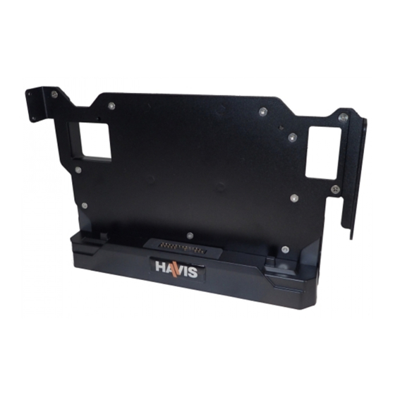
- Page 1 Owner’s Manual Havis Docking Station for Dell Latitude Rugged 12 Tablet DS-DELL-700 Series DS-DELL-701 DS-DELL-704 DS-DELL-702 DS-DELL-705 DS-DELL-703 DS-DELL-706 www.havis.com 1-800-524-9900...
-
Page 2: Zip Ties
Before Beginning (Original Instructions) Havis is pleased to provide this Owner’s Manual to aid in the proper installation and use of the DS-DELL-700 Series Docking Station for the Dell Latitude Rugged 12 Tablet. For questions regarding the set-up of your DS-DELL-700 Series Docking Station, please contact Havis at 1-800-524-9900 or visit www.havis.com for additional... - Page 3 • NO USE LA COMPUTADORA MIENTRAS CONDUCE. • READ ALL INSTRUCTIONS THOROUGHLY BEFORE BEGINNING INSTALLATION. • THE DS-DELL-700 SERIES SHIPS WITH A UNIQUE POWER CABLE AND IS EQUIPPED WITH AN INTERNAL POWER SUPPLY. REQUIRED INPUT VOLTAGE IS 10-18 VDC. IT IS RECOMMENDED TO WIRE THE POWER CABLE TO THE POWER SOURCE BY WAY OF A FUSE BLOCK WITH 10A FUSE MAX.
-
Page 4: Table Of Contents
Table of Contents Specifications Parts Included Port Replication Capability Cable Management Mounting Your Dell Latitude 12 Rugged Tablet Installation IP-65 Cable Installation Precautions • Do not place metal objects or containers of liquid on top of the Docking Station • If a malfunction occurs, immediately unplug the Power Cable and remove the tablet •... - Page 5 * - Removeable for tablet I/O access - Must be removed prior toTablet installation. Optional Mounting Mounting Holes (x4) Holes (x4) (VESA 75mm Hole Pattern) (RAM D202U) (1/4”-20 Thread) Ports Power Cable Input Strain Relief Point Cable Channels Power Cable I/O Cover www.havis.com • 1-800-524-9900...
-
Page 6: Port Replication Capability
USB 3.0 Serial RS232 Ethernet RJ45 (x3) Screen Blanking Solution (optional) PKG-DS-DELL-700 Series Docking Stations are equipped with Havis Screen Blanking Solution powered by Blank-It (Part # DS-DA-801). Always install Blank-It USB dongle in furthest left hand USB Port as shown. -
Page 7: Cable Management
Tablet I/O Cover Brackets from the Docking Station using a #2 Phillips driver (3 places). Connect Power Cable as shown and hand tighten. Do not over-tighten or damage to connector may result. Connect peripherals and route cables through cable channels as shown. www.havis.com • 1-800-524-9900... - Page 8 Cable Management (continued) Secure I/O Cover to Docking Station, being careful not to pinch cables. Use T8 Torx Bit (Hardware Kit Item #4) and (6x) #4-40 x 3/8” long Tamper-Proof Screws (Hardware Kit Item #3). Torque screws to 8 - 10 in-lbs (0.9 - 1.1 Nm). NOTE: If a DS-DELL-704/705/706 was purchased, go to page 11 for IP-65 Cable Installation prior to securing the I/O Cover to Docking Station.
-
Page 9: Mounting Your Dell Latitude 12 Rugged Tablet
------------ Les prises d’alignement de votre tablette s’aligneront avec les tiges d’alignement de la station d’accueil. ------------ Las guías de alineación de su tableta deben estar alineadas con los Postes de alineación de la Base Universal. www.havis.com • 1-800-524-9900... - Page 10 Mounting Your Dell Latitude 12 Rugged Tablet (continued) Orient Docking Station in an upright position. Hold tablet in landscape orientation, with bottom angled toward Docking Station. Lower tablet into the bottom of the Docking Station by aligning the tablet Alignment Sockets with the Docking Station’s Alignment Posts.
- Page 11 Tablet to Docking Station from the back side with T15 Tamper-Proof Torx Bit (Hardware Kit Item #4), using (2x) M4 x 25mm long Tamper-Proof Screws (Hardware Kit Item #2). Torque screws to 12 - 15 in-lbs (1.4 - 1.7 Nm). www.havis.com • 1-800-524-9900...
-
Page 12: Installation
Installation Remove the M4 screws (4 places) with T15 Tamper-Proof Torx Bit supplied. Be certain to retain screws, split lock washers, and flat washers for reassembly to compatible VESA 75 mounting equipment. Align with compatible VESA 75 hole pattern motion or mounting device and hand start M4 screws, split lock washers, and flat washers from prior step into Docking Station as shown below. - Page 13 DS-DELL-700 Series is equipped with mounting features required to secure a Ram D202U Ball Mount. If this mounting method is desired, secure Ram Ball (not included) to DS-DELL-700 Series as shown using (4x) 1/4”-20 x 1 /2” long flat head screws (not provided).
-
Page 14: Ip-65 Cable Installation
IP-65 Cable Installation DS-DA-104 Kit Contents • Sealing Element (x10) • Grease Pack (x1) (8 required for installation) • Caution Card Cable Sizing Diagram Cable Ø X -> Y 0.100” - 0.150” DO NOT INSTALL CABLES Cable Cable GREATER THAN Ø... - Page 15 IP-65 Cable Installation (continued) For IP-65 enclosure you may populate up to four (4) of the available I/O Ports in any combination. USB 3.0 Serial RS232 Ethernet RJ45 (x3) NOTE: If using a DS-DA-801 Screen Blanking USB dongle, it must be inserted in USB port Position Blank-It USB dongle as shown Identify the number of peripherals to be connected and measure respective...
- Page 16 IP-65 Cable Installation (continued) Using Sealing Element sizing from Page 11, choose appropriate orientation and apply a small amount of provided Silicone Grease to the opposite side perimeter of the Sealing Element and insert into corresponding housing receptacle on the Docking Station, greased end first. Repeat for all Cable Channels.
- Page 17 IP-65 Cable Installation (continued) Before installing I/O Cover to Docking Station, ensure all Sealing Elements are fully seated and cables are aligned with Sealing Elements as shown. www.havis.com • 1-800-524-9900...
- Page 18 IP-65 Cable Installation (continued) Carefully lower I/O Cover with Sealing Elements onto Docking Station and secure with (6x) #4-40 x 3/8” long Tamper-Proof Screws (Hardware Kit Item #3). Torque screws to 8 - 10 in-lbs (0.9 - 1.2 Nm). IT IS IMPORTANT TO TORQUE ALL SCREWS TO 8 - 10 in-lbs (0.9 - 1.2 Nm) TO ENSURE A COMPLETE SEAL BETWEEN I/O COVER AND DOCKING STATION ENCLOSURE.
- Page 19 Related Products Havis offers a wide variety of accessory products specifically for use with the DS-DELL-700 Series Docking Station. For more information or to order, please visit www.havis.com. DS-DA-218 Desktop Stand Durable stand for mounting your product in the home or office.
- Page 20 Havis, Inc. 75 Jacksonville Road Warminster, PA 18974 www.havis.com 1-800-524-9900 DS-DELL-700-SERIES_OMN_3-17...
Need help?
Do you have a question about the DS-DELL-700 Series and is the answer not in the manual?
Questions and answers