Table of Contents
Advertisement
Advertisement
Table of Contents

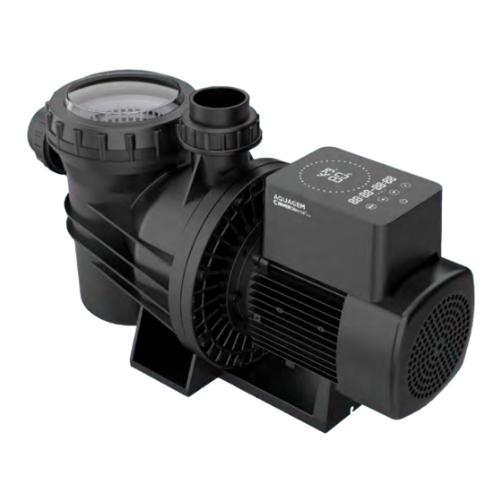
Summary of Contents for Aquagem XFIow INVERSilence GFVS09N
-
Page 2: Table Of Contents
CONTENTS 1. IMPORTANT SAFETY INSTRUCTIONS............1 2. TECHNICAL SPECIFICATIONS ..............1 3. OVERALL DIMENSION ................2 4. INSTALLATION .................... 2 5. SETTING & OPERATION ................4 6. WIRING CONNECTION ................6 7. EXTERNAL CONTROL(Not included in standard model) ....... 7 8. -
Page 3: Important Safety Instructions
IMPORTANT SAFE IMPORTANT SAFE TY INSTRUCTIONS This guide provides installation and operation instructions for this pump. Consult This guide provides installation and operation instructions for this pump. Consult This guide provides installation and operation instructions for this pump. Consult your supplier with any questions regarding this equipment. -
Page 4: Overall Dimension
2. OVERALL DIMENSION 2.1 GFVS09N & GFVS11N 3.2 GFVS15N & GFVS19N 4. INSTALLATION 4.1. Pump Location 1. Locate pump as close to pool as practical and run suction lines as direct as possible to reduce friction loss. 2.To avoid direct sunshine or heat, It is recommended to place pump indoor or in the shade. 3.Do NOT install pump in a damp or non-ventilated location. - Page 5 diameter. 3). Plumbing on the suction side of the pump should be as short as possible. 4). For most installations we recommend installing a valve on both the pump suction and return lines so that the pump can be isolated during routine maintenance. However, we also recommend that a valve, elbow or tee installed in the suction line should be no closer to the front of the pump than five times the suction line diameter.
-
Page 6: Setting & Operation
5. SETTING & OPERATION 5.1 Interface Manual Mode Timer Mode Backwash Mode Description On/off Lock/Backwash: When the screen is locked, press >3 seconds to unlock the screen; When the screen is unlocked, press it for backwash mode. Up: Increase value(capacity& time) Down: Decrease value(capacity&... - Page 7 5.3 Timer Setting *Overlap setting of time will be considered as invalid, the pump will only run based on the previous valid setting. *During timer setting, if you want to return to the previous setting, hold for 3 seconds. 1. enter timer setting 2.set current time 3.to next time 4.decide the specific capacity...
-
Page 8: Wiring Connection
6. WIRING CONNECTION WIRING CONNECTION Warning: All electrical wiring MUST conform with applicable National Electrical Safety Code All electrical wiring MUST conform with applicable National Electrical Safety Code All electrical wiring MUST conform with applicable National Electrical Safety Code (NESC) and National Electric Code (NEC). (NESC) and National Electric Code (NEC). -
Page 9: External Control(Not Included In Standard Model
7 . EXTERNAL CONTROL . EXTERNAL CONTROL ( Not included in standard model Not included in standard model ) External control can be enabled via following contacts. Pressing on/off can stop the pump External control can be enabled via following contacts. Pressing on/off can stop the pump External control can be enabled via following contacts. -
Page 10: Trouble Shooting
c. RS485: To enable external control p To enable external control p ump running capacity , connect terminal A and B, via , connect terminal A and B, via Modbus485 communication protocol. Modbus485 communication protocol. Display board RS485 8 . TROUBLE SHOOTING . -
Page 11: Error Code
ERROR CODE Item Code Description Analysis E001 Abnormal input voltage Not faulty E002 Output over current Not faulty E101 Heat sink over heat Contact your supplier E102 Heat sink sensor error Contact your supplier E103 Master driver board error Contact your supplier E201 Circuit board error Contact your supplier... -
Page 12: Warranty & Exclusions
11. WARRANTY & EXCLUSIONS Should a defect become evident during the term of warranty, at its option, the manufacturer will repair or replace such item or part at its own cost and expense. Customer will need to follow the warranty claim procedures in order to obtain the benefit on this warranty. Under no circumstances should the manufacturer be held liable for any consequences resulting from inappropriate, incorrect installation, or mismatching of the product to pool pumps that are not compatible.


Need help?
Do you have a question about the XFIow INVERSilence GFVS09N and is the answer not in the manual?
Questions and answers