Table of Contents
Advertisement
Quick Links
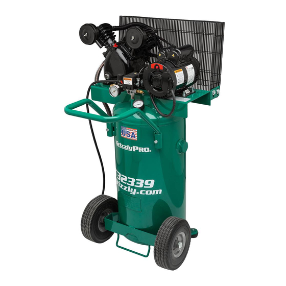
MODEL T32339
20-GALLON 2 HP PORTABLE
AIR COMPRESSOR
OWNER'S MANUAL
(For models manufactured since 03/21)
COPYRIGHT © JUNE, 2022 BY GRIZZLY INDUSTRIAL, INC.
WARNING: NO PORTION OF THIS MANUAL MAY BE REPRODUCED IN ANY SHAPE
OR FORM WITHOUT THE WRITTEN APPROVAL OF GRIZZLY INDUSTRIAL, INC.
#CS22295 PRINTED IN USA
V1.06.22
***Keep for Future Reference***
Advertisement
Table of Contents

Subscribe to Our Youtube Channel
Related Manuals for Grizzly T32339


Summary of Contents for Grizzly T32339
- Page 1 (For models manufactured since 03/21) COPYRIGHT © JUNE, 2022 BY GRIZZLY INDUSTRIAL, INC. WARNING: NO PORTION OF THIS MANUAL MAY BE REPRODUCED IN ANY SHAPE OR FORM WITHOUT THE WRITTEN APPROVAL OF GRIZZLY INDUSTRIAL, INC. #CS22295 PRINTED IN USA V1.06.22...
- Page 2 This manual provides critical safety instructions on the proper setup, operation, maintenance, and service of this machine/tool. Save this document, refer to it often, and use it to instruct other operators. Failure to read, understand and follow the instructions in this manual may result in fire or serious personal injury—including amputation, electrocution, or death.
-
Page 3: Table Of Contents
Table of Contents INTRODUCTION ..........................2 Contact Info ..........................2 Manual Accuracy ........................2 Identification ..........................3 Controls & Components ......................4 Machine Data Sheet ........................6 SECTION 1: SAFETY ........................8 Safety Instructions for Machinery ....................8 Additional Safety for Air Compressors ..................10 SECTION 2: POWER SUPPLY ...................... -
Page 4: Introduction
ID label (see below). This information is required for us to provide proper tech support, and it helps us determine if updated documentation is available for your machine. Manufacture Date Serial Number Model T32339 (Mfd. Since 03/21) -
Page 5: Identification
Valve Gauge Exhaust Line Pressure Tank Tube Gauge Quick-Connect Port Wheel (1 of 2) Drain Valve Machine Foot (1 of 2) To reduce your risk of serious injury, read this entire manual BEFORE using machine. Model T32339 (Mfd. Since 03/21) -
Page 6: Controls & Components
Figure 2. Lower air input components. E. Tank: Holds up to 20 gallons of pressurized air. Drain Valve: Drains built-up moisture from tank when ball valve is opened. Model T32339 (Mfd. Since 03/21) - Page 7 OFF position, wait a few minutes for motor to cool, then press motor reset button. If motor does not reset, allow motor to cool longer, then try Figure 4. Pressurization components. again. Model T32339 (Mfd. Since 03/21)
-
Page 8: Machine Data Sheet
Phase ..................................Single-Phase Amps ..............................15A at 115V, 7.5A at 230V Speed ..................................3450 RPM Type ................................ODP Capacitor-Start Power Transfer ..................................Belt Bearings ..........................Shielded & Permanently Lubricated Centrifugal Switch/Contacts Type ..........................External Model T32339 (Mfd. Since 03/21) Model T32339 Page 1 of 2... - Page 9 Cut-Out Pressure ..............................125 PSI Cut-In Pressure ..............................95 PSI Duty Cycle ................................50/50 Tank Size ................................ 20 Gallons Number of Cylinders ................................2 Pump Lubrication ..............Grizzly Model T28041 or Equivalent Air Compressor Oil Drain Valve Type ...............................Ball Valve Regulator ..................................Yes Output Port Information Connection Type ............................Quick-Coupler Connection Size ..............................
-
Page 10: Section 1: Safety
Never operate under the influence of drugs or injury or blindness from flying particles. Everyday alcohol, when tired, or when distracted. eyeglasses are NOT approved safety glasses. Model T32339 (Mfd. Since 03/21) - Page 11 Make sure they are properly installed, you experience difficulties performing the intend- undamaged, and working correctly BEFORE ed operation, stop using the machine! Contact our operating machine. Technical Support at (570) 546-9663. Model T32339 (Mfd. Since 03/21)
-
Page 12: Additional Safety For Air Compressors
Do not use compres- moving or servicing to prevent impact injuries, soft sor to inflate low-pressure objects that are likely to tissue injuries, and burns. burst (like children’s toys). -10- Model T32339 (Mfd. Since 03/21) -
Page 13: Section 2: Power Supply
Nominal Voltage ..208V, 220V, 230V, 240V Cycle ............60 Hz Phase ........... Single-Phase Power Supply Circuit ......15 Amps Plug/Receptacle ......NEMA 6-15 -11- Model T32339 (Mfd. Since 03/21) - Page 14 Maximum Length (Shorter is Better)..50 ft. the included power cord. The plug must only be inserted into a matching receptacle (see following figure) that is properly installed and grounded in accordance with all local codes and ordinances. -12- Model T32339 (Mfd. Since 03/21)
-
Page 15: Converting Voltage To 230V
6-15 Plug (As Recommended) PRESSURE Figure 10. Motor wired for 230V power supply. SWITCH Install motor wiring cover. LEFOO LF10-4H Figure 8. Location of motor wiring cover and bolts. PRESSURE -13- Model T32339 (Mfd. Since 03/21) - Page 16 Power Wires Supply Wires Neutral PRESSURE PRESSURE Ground SWITCH 115 VAC SWITCH LEFOO LF10-4H 5-15 Plug LEFOO LF10-4H Figure 13. 6-15 plug installed. Figure 12. Location of wires to remove. Install pressure switch cover. -14- Model T32339 (Mfd. Since 03/21)
-
Page 17: Section 3: Setup
Grizzly or the shipping agent. You MUST have the original pack- Inventory (Figure 14) aging to file a freight claim. -
Page 18: Site Considerations
Only install in an Shadows, glare, or strobe effects that may distract access restricted location. or impede the operator must be eliminated. Wall Electrical Min. 18" from Connection Obstructions 23" 24" Figure 15. Minimum working clearances. -16- Model T32339 (Mfd. Since 03/21) -
Page 19: Test Run
To test run machine: tion to turn machine ON and verify motor operation. Check oil level (refer to Lubrication on Page 25 for instructions). Motor should run smoothly and without unusual problems or noises. -17- Model T32339 (Mfd. Since 03/21) - Page 20 13. Check oil level (refer to Lubrication on Page connect it from power. Safety feature of 25 for instructions). check valve is NOT working properly and must be replaced before further using Congratulations! Test Run is complete. machine. -18- Model T32339 (Mfd. Since 03/21)
-
Page 21: Section 4: Operations
Puts on safety glasses. ects. Regardless of the content in this sec- tion, Grizzly Industrial will not be held liable Pulls safety valve ring to test valve and clear for accidents caused by lack of training. -
Page 22: Choosing Air Hose
The hose length must allow for the air compressor to remain Figure 21. Example of male and female fittings. at least 20 feet away from the operation. The outlet port on the T32339 is a ⁄ " NPT female Diameter quick-coupler (see Figure 22), so you will need a ⁄... -
Page 23: Connecting Air Tool
Airflow Delivery (CFM) The Model T32339 has a regulator and pressure The first consideration when choosing an air tool gauge for controlling and observing line pressure. - Page 24 Figure 25. Plug inserted into coupler. Figure 26. Pushing coupler sleeve to release Connect other end of hose to air tool. plug. Note: Refer to air tool instructions for speci- fications, method of connection, and proper use of tool. -22- Model T32339 (Mfd. Since 03/21)
-
Page 25: Section 5: Accessories
T20451—“Kirova” Clear Safety Glasses To reduce this risk, only install accessories T20456—DAKURA Safety Glasses, Black/Clear recommended for this machine by Grizzly. NOTICE T20503 Refer to our website or latest catalog for additional recommended accessories. -
Page 26: Section 6: Maintenance
Quarterly (3 Month/500 Hour) Maintenance • Change compressor oil. Semi-Annual (6 Month) Maintenance • Check hoses/connections for leaks. If soapy water at suspected leak creates bubbles, air is escaping. Repair or replace affected parts. -24- Model T32339 (Mfd. Since 03/21) -
Page 27: Draining Tank
Figure 30. Drain valve handle open. Oil Sight Lubrication Glass The oil level in the Model T32339 should be checked daily to prevent overheating and dam- Figure 32. Location of oil sight glass and oil fill age to the compressor. Change the oil every 500 plug. -
Page 28: Checking Air Filters
Part #16 in Parts beginning on Page 41). (see Figure 32 on Page 25), then install fill plug. Repeat Step 3 for second filter. -26- Model T32339 (Mfd. Since 03/21) -
Page 29: Checking/Adjusting Belt Tension
— If V-belt is damaged, replace belt. Pump Belt Guard Motor Figure 35. Location of belt guard and fasteners. V-Belt Figure 37. Location of belt tension components. -27- Model T32339 (Mfd. Since 03/21) -
Page 30: Checking For Leaks
Step 5. Spray suspected air leak with soap and water solution and look for air bubbles. — If bubbles do not form, repeat at different location. — If bubbles do form, proceed to Fixing Leaks. -28- Model T32339 (Mfd. Since 03/21) -
Page 31: Machine Storage
Cover machine with tarp or plastic sheet that will keep out dust and resist liquid or mois- ture. If machine will be stored in/near direct sunlight, use cover that will block UV rays. Figure 38. T23951 Blue Tarp 8' x 10'. -29- Model T32339 (Mfd. Since 03/21) -
Page 32: Section 7: Service
10. Run capacitor at fault. 10. Test/repair/replace. 11. Extension cord too long. 11. Move machine closer to power supply; use shorter extension cord. 12. Clean/replace check valve components (Page 33). 12. Check valve components are dirty/damaged. -30- Model T32339 (Mfd. Since 03/21) - Page 33 5. Check air tank, pipes, and all connections for leaks (Page 28). Do not attempt to repair leaking/damaged tank, only replace. 6. Check valve components are dirty/damaged. 6. Clean/replace check valve components (Page 33). -31- Model T32339 (Mfd. Since 03/21)
- Page 34 2. Safety relief valve at fault. 2. Test/replace. 3. Turn compressor OFF, disconnect from power, and 3. Pressure switch at fault. empty tank. DO NOT USE until switch is replaced. -32- Model T32339 (Mfd. Since 03/21)
-
Page 35: Inspecting Check Valve
Pencil or Hex Wrench (6mm or Less) ....1 Eye injury hazard! Always wear safety glasses when handling pressurized air Drain Valve system. Handle To inspect check valve: Figure 39. Drain valve handle open. DISCONNECT MACHINE FROM POWER! -33- Model T32339 (Mfd. Since 03/21) - Page 36 Figure 41. Location of discharge line nut, check valve elbow, and check valve. Press disc with pencil or hex wrench (see Figures 42–43). Disc should depress when pressed, then spring back to original position when released. -34- Model T32339 (Mfd. Since 03/21)
-
Page 37: Adjusting Cut-In/Cut-Out Settings
Flat Head Screwdriver ⁄ " ........1 To adjust cut-in/cut-out settings: Cut-In/ Cut-Out Operate compressor and record cut-in and Adjustment cut-out pressures. Screw DISCONNECT MACHINE FROM POWER! Figure 45. Location of cut-in/cut-out adjustment screw. -35- Model T32339 (Mfd. Since 03/21) -
Page 38: Aligning Motor Pulley To Pump Flywheel
Belt, pulley, and flywheel will be hot after operation. Allow them to cool before handling. Cut-Out Adjustment Screw To align motor pulley to pump flywheel: DISCONNECT MACHINE FROM POWER! Figure 46. Location of cut-out only adjustment screw. -36- Model T32339 (Mfd. Since 03/21) - Page 39 V-belt at "A", "B", and "C" locations shown in Figure 49. — If measurements are all within ⁄ " of each other, pulley and flywheel are coplanar and do not need to be adjusted. Proceed to Step 7. -37- Model T32339 (Mfd. Since 03/21)
-
Page 40: Section 8: Wiring
Technical Support at (570) 546-9663. The photos and diagrams included in this section are best viewed in color. You can view these pages in color at www.grizzly.com. -38- Model T32339 (Mfd. Since 03/21) -
Page 41: Wiring Diagram
30uF 370V Ground 6-15 Plug Motor Prewired (As Recommended) for 115V Neutral Motor Rewired for 230V PRESSURE Ground SWITCH 115 VAC LEFOO LF10-4H 5-15 Plug (Rewired for 230V) READ ELECTRICAL SAFETY -39- Model T32339 (Mfd. Since 03/21) ON PAGE 38! -
Page 42: Electrical Component Photos
Electrical Component Photos Figure 51. Pressure switch wiring. Figure 53. Capacitor wiring. Figure 52. Motor wiring (115V). READ ELECTRICAL SAFETY -40- Model T32339 (Mfd. Since 03/21) ON PAGE 38! -
Page 43: Section 9: Parts
SECTION 9: PARTS To order parts, contact MEGA by phone at (832) 415-6995 or email at CS@megacompressor.com. Pump -41- Model T32339 (Mfd. Since 03/21) - Page 44 LOCK WASHER 8MM HEX BOLT M6-1 X 40 HEX BOLT M8-1.25 X 20 FLAT WASHER 6MM BREATHER CAP T-ELBOW FITTING COMPRESSOR PULLEY HEX NUT 3/4-16 FLAT WASHER 8MM FIN TUBE HEX BOLT M8-1.25 X 35 -42- Model T32339 (Mfd. Since 03/21)
-
Page 45: Tank & Motor
Tank & Motor -43- Model T32339 (Mfd. Since 03/21) - Page 46 QUICK COUPLER 1/4" NPT MOTOR PULLEY HEX BOLT M8-1.25 X 16 SET SCREW M4-.7 X 10 HEX BOLT M8-1.25 X 30 V-BELT A43 HEX NUT M8-1.25 HEX BOLT M6-1.25 X 16 TANK HANDLE BELT GUARD -44- Model T32339 (Mfd. Since 03/21)
-
Page 47: Labels & Cosmetics
Safety labels help reduce the risk of serious injury caused by machine hazards. If any label comes off or becomes unreadable, the owner of this machine MUST replace it in the original location before resuming operations. For replacements, contact (800) 523-4777 or www.grizzly.com. -45-...
Need help?
Do you have a question about the T32339 and is the answer not in the manual?
Questions and answers