Table of Contents
Advertisement
Quick Links
Advertisement
Table of Contents

Related Manuals for tams elektronik Booster B-3


Summary of Contents for tams elektronik Booster B-3
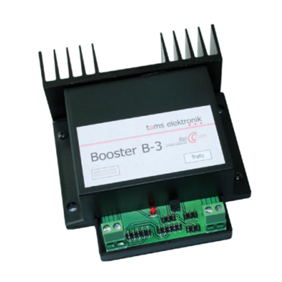
- Page 1 Manual Booster B-3 Item no. 40-19327 tams elektronik n n n...
-
Page 2: Table Of Contents
11. EU declaration of conformity............20 12. Declarations conforming to the WEEE directive......20 © 09/2016 Tams Elektronik GmbH All rights reserved. No part of this publication may be reproduced or transmitted in any form or by any means, electronic or mechanical, including photocopying, without prior permission in writing from Tams Elektronik GmbH. -
Page 3: Why Boosters
10% of the calculated sum of power consumption The Booster B-3 can provide 2,5 A current. If your overall power demand exceeds the capacity of one booster you have to connect additional boosters according to the special requirements of your layout. -
Page 4: Getting Started
Any other use is inappropriate and invalidates any guarantees. The booster B-3 should not be mounted by children under the age of Reading, understanding and following the instructions in this manual are mandatory for the user. - Page 5 Booster B-3 English Required materials In order to connect the booster you need: Wire. Recommended diameter: for the connection to the transformer and the rails: > 1,5 mm² for the connection to the digital control unit: > 0,25 mm²...
-
Page 6: Safety Instructions
English Booster B-3 3. Safety instructions Risk of fire The booster is cooled by a heat sink to prevent overheating. Thus be careful to allow the air to flow unhindered through the heat sink at the booster´s back. If the airflow is blocked components can overheat and catch fire. -
Page 7: Your B-3
Booster B-3 English 4. Your B-3 Technical specifications Supply voltage 12 - 20 V AC voltage or 14 – 21 V DC voltage Maximum output current 2,5 A Output voltage 12, 15 or 19 Volt digital voltage Power max. 48 Watt... - Page 8 Track voltage Operation display (LED) Ports The booster B-3 can be connected either to a port for a Märklin- compatible booster or to a DCC-conforming booster port. Advice: The port ( Märklin-compatible or DCC-conform) used for the booster´s connection to the control unit, is of no importance for the data format used to control the decoders.
- Page 9 The DCC-input of the B-3 is isolated through an opto-coupler. Balanced track voltage The booster B-3 provides a regulated track voltage, which can be set to a value of 12, 15 or 19 V. At delivery the track voltage is set to 19 V.
- Page 10 English Booster B-3 Short-circuit protection The Booster B-3 provides an intergrated short circuit breaking in shape of an integrated current limitation. This causes the booster to switch off automatically when a short circuit occurs at the track output and thus prevents damages to the booster, the tracks and the vehicles.
-
Page 11: Splitting Your Model Railway Layout
Booster B-3 English 5. Splitting your model railway layout Split your model railway layout in several track sections electrically isolating them from each other. Every section has to be supplied by a booster of its’ own. In each section a maximum of three to five locomotives should run at the same time. -
Page 12: Connecting The B-3
MasterControl has to be set to "short circuit polarity: positive (MM)" (= factory setting). The booster B-3 has two Märklin-booster ports and two DCC-booster ports to be used at choice. Please make sure that the pin assignment of the central unit´s booster interface corresponds to that of the booster... - Page 13 Booster B-3 English Pin assignment of the booster ports Märklin booster port DCC booster port short circuit warning wire short circuit warning wire earth data (-) direct voltage appr.+ 19 V data (+) booster "on / off" data Connecting an additional booster To connect an additional booster please use the Märklin or DCC booster...
- Page 14 English Booster B-3 Connecting the tracks Connect the booster´s track port to both rails (with 2-rail systems) or to one rail and the middle conductor (with 3-rail systems). These connections should be repeated every 2-3 meters, because the resistance at the connection points of the tracks is quite high. When choosing too high intervals, problems with the short circuit indication or the power supply of the vehicles may occur.
- Page 15 Booster B-3 English Connection to a DCC port Connection to a Märklin port Page 15...
-
Page 16: Settings
English Booster B-3 7. Settings With the B-3, you can set a track voltage of 12, 15 or 19 V and switch on or off RailCom. Position the short circuit jumpers included in the package in concordance with the drawings to the corresponding pins on the PCB. -
Page 17: Operation
Booster B-3 English 8. Operation The LED on the front lights or flashes indicating the operation modes or problems that occur. Meaning constantly lighting booster in operation slowly flashing no signal from the control unit (apprx. 1 sec. cycle) quickly flashing... - Page 18 English Booster B-3 The LED flashes slowly. Possible reason: The control unit has been switched off or the connection to the control unit has been interrupted. à Check the control unit and the connections. The LED flashes quickly.
-
Page 19: Guarantee Bond
Booster B-3 English 10. Guarantee bond For this product we issue voluntarily a guarantee of 2 years from the date of purchase by the first customer, but in maximum 3 years after the end of series production. The first customer is the consumer first... -
Page 20: Eu Declaration Of Conformity
English Booster B-3 11. EU declaration of conformity This product conforms with the EC-directives mentioned below and is therefore CE certified. 2004/108/EG on electromagnetic. Underlying standards: EN 55014-1 and EN 61000-6-3. To guarantee the electromagnetic tolerance in operation you must take the following precautions: ... - Page 21 Booster B-3 English Page 21...
- Page 22 English Booster B-3 Page 22...
- Page 23 Booster B-3 English Page 23...
- Page 24 Information and tips: http://www.tams-online.de Warranty and service: Tams Elektronik GmbH Fuhrberger Straße 4 DE-30625 Hannover fon: +49 (0)511 / 55 60 60 fax: +49 (0)511 / 55 61 61 e-mail: modellbahn@tams-online.de...
Need help?
Do you have a question about the Booster B-3 and is the answer not in the manual?
Questions and answers