Table of Contents

Related Manuals for Phcbi MDF-U700VX Series


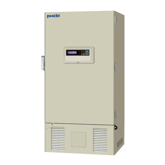
Summary of Contents for Phcbi MDF-U700VX Series
- Page 1 Operating Instructions Ultra-Low Temperature Freezer MDF-U700VX MDF-U700VXC Series Please read the operating instructions carefully before using this product, and keep the operating instructions for future use. See page 45 for all model numbers.
-
Page 3: Table Of Contents
CONTENTS INTRODUCTION ········································································· 2 PRECAUTIONS FOR SAFE OPERATION ········································· 3 ENVIRONMENTAL CONDITIONS ··················································· 7 FREEZER COMPONENTS ···························································· 8 Control panel ········································································· 10 REMOTE ALARM TERMINAL ······················································· 11 AIR INTAKE PORT ····································································· 11 INSTALLATION SITE ··································································· 12 INSTALLATION ·········································································· 13 START-UP OF UNIT ··································································· 14 DURING/AFTER POWER FAILURE ···············································... -
Page 4: Introduction
INTRODUCTION ■ Read the operating instructions carefully before using the product and follow the instructions for safe operation. ■ PHC Corporation takes no responsibility for safety if the product is not used as intended or is used with any procedures other than those given in the operating instructions. ■... -
Page 5: Precautions For Safe Operation
PRECAUTIONS FOR SAFE OPERATION It is imperative that the user complies with the operating instructions as it contains important safety advice. Items and procedures are described so that you can use this unit correctly and safely. If the precautions advised are followed, this will prevent possible injury to the user and any other person. - Page 6 PRECAUTIONS FOR SAFE OPERATION WARNING Do not use the unit outdoors. Current leakage or electric shock may result if the unit is exposed to rain water. Only qualified engineers or service personnel should install the unit. The installation by unqualified personnel may cause electric shock or fire. Install the unit on a sturdy floor and take an adequate precaution to prevent the unit from turning over.
- Page 7 PRECAUTIONS FOR SAFE OPERATION WARNING Ensure you do not inhale or consume medication or aerosols from around the unit at the time of maintenance. These may be harmful to your health. Never splash water directly onto the unit as this may cause electric shock or short circuit. Never put cylinders with liquid on the unit as this may cause electric shock or short circuit when the liquid is spilled.
- Page 8 PRECAUTIONS FOR SAFE OPERATION CAUTION This unit must be plugged into a dedicated circuit protected by branch circuit breaker. Use a dedicated power source as indicated on the rating label attached to the unit. A multiple-tap may cause fire resulting from abnormal heating. Connect the power supply plug to the power source firmly after removing the dust on the plug.
-
Page 9: Environmental Conditions
ENVIRONMENTAL CONDITIONS This equipment is designed to be safe at least under the following conditions (based on the IEC 61010-1): ■ Indoor use; ■ Altitude up to 2000 m; ■ Ambient temperature 5 C to 40 ■ Maximum relative humidity 80 % for temperature up to 31 C decreasing linearly to 50 % relative humidity at 40 ■... -
Page 10: Freezer Components
FREEZER COMPONENTS Shelf Space for interface board POWER A compressor B compressor Rear side... - Page 11 FREEZER COMPONENTS 1. Outer door: Hold the handle and open the outer door. On closing, lock the outer door latch completely. 2. Inner door: The operation of the inner door should be quick to minimize the temperature rise in chamber. Lock the inner door latch completely when the inner door is closed. The inner door is removable for cleaning or defrosting.
-
Page 12: Control Panel
FREEZER COMPONENTS Control panel 1. LCD panel 2. Alarm lamp (ALARM): This lamp is flashed during alarm condition. 3. Figure input key: User for operation setting. 4. Menu button (MENU): To open the menu window during setting. 5. Shift key (Upward, downward, rightward, leftward): To move the cursor on the LCD panel during setting. -
Page 13: Remote Alarm Terminal
REMOTE ALARM TERMINAL The terminal of the remote alarm is installed at the lower left side of the unit. The alarm is outputted from this terminal. Contact capacity is DC 30 V, 2 A. Contact output: Terminal Normal status Abnormal status Between COM. -
Page 14: Installation Site
INSTALLATION SITE To operate this unit properly and to obtain maximum performance, install the unit in a location with the following conditions: ■ A location not subjected to direct sunlight Do not install the unit under direct sunlight. Installation in a location subjected to direct sunlight cannot obtain the intended performance. -
Page 15: Installation
INSTALLATION 1. Remove the packaging materials and tapes Remove all transportation packaging materials and tapes. Open the doors and ventilate the unit. If the outside panels are dirty, clean them with a diluted neutral dishwashing detergent. (Undiluted detergent can damage the plastic components. For the dilution, refer to the instruction of the detergent.) After the cleaning with the diluted detergent, always wipe it off with a wet cloth. -
Page 16: Start-Up Of Unit
START-UP OF UNIT Use the following procedure to start trial operation or actual operation of the unit. 1. Turn off the switch of the backup cooling kit (optional component) if it is installed. 2. Connect the power supply cord to the dedicated outlet having appropriate rating with the chamber empty, and turn on the power switch on the freezer. -
Page 17: Function Of Control Panel
FUNCTION OF CONTROL PANEL The following functions are available through control panel:. 1. Setting of standby operation: To set a running condition at the start-up. (refer to page 17) 2. Setting of log interval and sending to PC: To set a log interval (page 30) and to send a log data to PC. -
Page 18: Top Screen Of Control Panel
TOP SCREEN OF CONTROL PANEL When the power switch is turned on, the top screen is displayed on the LCD panel. 1. Operation indication (Control): "Normal" (initialization value) is indicated by the normal operation. "ECO" is indicated in the saving energy mode. Refer to page 26. 2. -
Page 19: Running Operation (Menu/Set)
RUNNING OPERATION (MENU/Set) This product is operated with set temperature at the time of start-up. 1. With the top screen displayed, press the menu button (MENU) to show the menu window. Select “Set”, and press the enter key (ENTER). 2. A setup screen (Temp. Setting) is displayed. Set up each parameter. 1. -
Page 20: Chamber Temperature Setting (Temperature)
RUNNING OPERATION (MENU/Set) Chamber temperature setting (Temperature) Table 1 shows the procedure for setting the chamber temperature. Perform key operations in the sequence indicated in the table. The example in the table is based on the assumption that the desired temperature is -75 Note: The unit is set at the factory that the chamber temperature -80 C. -
Page 21: Alarm Temp. Setting (High Alarm/Low Alarm)
RUNNING OPERATION (MENU/Set) Alarm temp. setting (High Alarm/Low Alarm) As an example, Table 2 shows the procedure to set the high temperature alarm so that the alarm can activate when the chamber temperature is 5 C higher than the set temperature. Table 3 shows the procedure to set the low temperature alarm so that the alarm can activate when the chamber temperature is 5 C lower than the set temperature. -
Page 22: Alarm Delay Time Setting (Alarm Delay)
RUNNING OPERATION (MENU/Set) Alarm delay time setting (Alarm Delay) The setting range for delay time is between 0 minute and 15 minutes. When 0 is set, the alarm buzzer sound without delay. The factory setting is 15 minutes. Table 4 shows the procedure for setting the alarm delay time. -
Page 23: Ring Back Of Alarm Buzzer Setting (Ring Back)
RUNNING OPERATION (MENU/Set) Ring back of alarm buzzer setting (Ring Back) The alarm buzzer is silenced by pressing buzzer stop key (BUZZER) on the control panel during alarm condition (The remote alarm is not canceled). The buzzer will be activated again after certain suspension if the alarm condition is continued. -
Page 24: Key Lock Function
RUNNING OPERATION (MENU/Set) Key lock function This unit is provided with the key lock function. When the key lock is ON, change of temperature setting through the key pad is not available. The key lock is set in OFF at the factory. If a key lock is on, the Temp. -
Page 25: Key Lock Release Function
RUNNING OPERATION (MENU/Set) Key lock release function Table 7. Procedure for key unlock setting (Change from Lock to Unlock) (Factory setting of PW is “0000”.) Description of operation Key operated Indication after operation ----- Top screen is displayed The menu window is indicated. And the MENU Press the MENU button. -
Page 26: Various Setting (Menu/Log)
VARIOUS SETTING (MENU/Log) Display of log (Log) This product has the function to record chamber temperature. (Initialization value is for about 5 weeks by the record interval for fifteen minutes.) This record is seen by the log indication (Log) of the display, or data can be transmitted to the personal computer. -
Page 27: Indication Of Log And Transmission
VARIOUS SETTING (MENU/Log) Indication of log and transmission Table 9 : Display indication and the process to transmit past all date chamber temperature record value Description of operation Key operated Indication after operation ----- Top screen is displayed. The menu window is indicated. And the MENU Press the MENU button. -
Page 28: Pc Setting
VARIOUS SETTING (MENU/Log) PC setting As for setting in PC side for transmission of log data, please contact our sales representative or agent. VARIOUS SETTING (MENU/Tools) You can change various settings with the Tools. 1. From the Top screen of the LCD panel section, press the menu button (MENU). The menu window is indicated. -
Page 29: Initialization (Tools/Default Setting)
VARIOUS SETTING (MENU/Tools) Initialization (Tools/Default Setting) 1. Choose initialization (Default Setting) with a shift key in the Select Tools screen (Select Tools). An initialization screen is indicated when a menu button (MENU) is pressed and made to indicate a menu window and OK is chosen and an enter key (ENTER) is pressed. -
Page 30: Set Of Date And Time (Tools/Date Time)
VARIOUS SETTING (MENU/Tools) Set of date and time (Tools/Date Time) Table 10 Setting of date and time (When time is set up at 12:00:00 on December 1, 2009 ) Description of operation Key operated Indication after operation Top screen is displayed. ----- The menu window is indicated. -
Page 31: Set Of Door Alarm Delay Time (Tools/Door Delay)
VARIOUS SETTING (MENU/Tools) Set of door alarm delay time (Tools/Door Delay) This product has the setup function of the door alarm delay time. (Factory setting is 2 minutes.) The variable range of the door alarm delay time is 0 minute to 15 minutes. A setup example is the following. Table 11 Door alarm delay time set-up steps (When door alarm delay time is changed from 2 minutes to 10 minutes.) Description of operation... -
Page 32: Set Of Log Interval (Tools/Log Interval)
VARIOUS SETTING (MENU/Tools) Set of log interval (Tools/Log Interval) This product can change the set point of the log interval (Log Interval) between 2 minutes and 30 minutes. (Factory setting is 15 minutes.) It can be recorded for about 5 weeks when the log interval is 15 minutes. -
Page 33: Change Of Compressor Delay Time (Tools/Comp. Delay)
VARIOUS SETTING (MENU/Tools) Change of compressor delay time (Tools/Comp. Delay) It is possible to set the time from turning ON this unit until starting its compressor. Settable range: 3 minutes~15 minutes, factory setting: 3 minutes. Note: • This unit has two compressor A and B. The compressor A starts first, after 1 minute the compressor B starts. -
Page 34: Set Of Key Lock Password (Tools/Key Lock Pw Setting)
VARIOUS SETTING (MENU/Tools) Set of key lock password(Tools/Key Lock PW Setting) 1. Select "Key lock PW setting" on the setting screen (Select Tools) and press the enter key (ENTER). Input the present password (4 digits), select “OK” and press the enter key (ENTER). (Factory setting is 0000.) L o c k . -
Page 35: Monitor Of Freezer Status
MONITOR OF FREEZER STATUS This product has the operation monitor system shown in the table 14. It is the system to detect and inform some hard operating conditions that leaving the unit operating may cause a failure. Operation conditions are indicated in the display of status (Status) and the message column on the top screen. Table 14 Operation monitor system (STATUS) list Status Indication... -
Page 36: Alarms & Safety Functions
ALARMS & SAFETY FUNCTIONS This product has the alarm & safety function of the table 15. Table 15 Alarm & safety function list Alarm & safety Situation Indication Buzzer Safety operation Alarm lamp flashed If the chamber temperature is Temp. indicator is flashed higher than the temperature at High temp. - Page 37 ALARMS & SAFETY FUNCTIONS Table 15. Alarms & safety function list Alarm & safety Situation Indication Buzzer Safety operation Message column: If the thermal sensor is disconnected. “Error 01: Temp Sensor Remote alarm. Open.” Intermittent tone Unit is continuous Message column: running.
-
Page 38: Routine Maintenance
ROUTINE MAINTENANCE WARNING Always disconnect the power supply to the unit prior to any repair or maintenance of the unit in order to prevent electric shock or injury. Ensure you do not inhale or consume medication or aerosols from around the unit at the time of maintenance. -
Page 39: Cleaning Of Air Intake Port
ROUTINE MAINTENANCE Cleaning of air intake port Using the cap for air vent is likely to build a frost in/around the air intake port. Clean it in the case shown below. Condition Check / Remedy When frost and ice can be The pipe of the air intake port is thrust with a stick for air intake port seen in the air intake port. -
Page 40: Replacement Of Battery
REPLACEMENT OF BATTERY Replace the battery for power failure alarm every 3 years (when “Please exchange a battery.” is displayed in the message column) to ensure the alarm is operated in the event of power failure. Contact our sales representative or agent for the replacement of battery. ... -
Page 41: Troubleshooting
TROUBLESHOOTING If the unit malfunctions, check out the following before calling for service. Malfunction Check/Remedy □ The unit is not connected to the power supply. If nothing operates even □ There is a power failure. when switched on □ The fuse is blown or the circuit breaker is activated. Check the following when a buzzer sounds or when the alarm lamp An alarm system works lights. -
Page 42: Disposal Of Unit
DISPOSAL OF UNIT WARNING If the unit is to be stored unused in an unsupervised area for an extended period ensure that children do not have access and doors cannot be closed completely with a key. The disposal of the unit should be accomplished by appropriate personnel. Always remove doors to prevent accidents such as suffocation. -
Page 43: Temperature Recorder (Option)
TEMPERATURE RECORDER (OPTION) The chamber temperature can be monitored and recorded by installing an optional temperature recorder. For the installation of a temperature recorder, an optional recorder fixing is necessary. For the attachment of a temperature recorder, contact our sales representative or agent. ... -
Page 44: Backup Cooling Kit (Option)
BACKUP COOLING KIT (OPTION) WARNING As with any equipment that uses CO gas, there is a likelihood of oxygen depletion in the vicinity of the equipment. It is important that you assess the work site to endure there is suitable and sufficient ventilation. -
Page 45: Inventry Rack (Option)
INVENTORY RACK (OPTION) The optional inventory racks (IR-220U, IR-224U) are useful to store the precious materials in the chamber effectively. When the racks are used, it is necessary to adjust the height of the shelves. Set the shelf stopper as shown in the figure below. IR-220U IR-224U NOTE:... -
Page 46: Specifications
SPECIFICATIONS Product name Ultra-Low Temperature Freezer Ultra-Low Temperature Freezer MDF-U700VX MDF-U700VXC External dimensions W1010 mm x D870 mm x H2010 mm Internal dimensions W870 mm x D600 mm x H1400 mm Effective capacity 728 L Exterior Painted steel Interior Painted steel Outer door Painted steel Inner door... -
Page 47: Performance
PERFORMANCE Product name Ultra-Low Temperature Freezer MDF-U700VX Model No. MDF-U700VX-PB MDF-U700VX-PK Cooling performance C at the center of the chamber (ambient temperature; 30 C, no load)* Temperature control range C to -86 C (ambient temperature; 30 C, no load) Rated voltage AC 220 V AC 220 V Rated frequency... -
Page 48: Safety Check Sheet
CAUTION Please fill in this form before servicing. Hand over this form to the service engineer to keep for his and your safety. Safety check sheet 1. Freezer contents : □ □ Risk of infection: □ □ Risk of toxicity: □... - Page 52 1-1-1 Sakada, Oizumi-machi, Ora-gun, Gunma 370-0596, Japan Printed in Japan LDCL032700-0 S0418-0 © PHC Corporation 2018...
Need help?
Do you have a question about the MDF-U700VX Series and is the answer not in the manual?
Questions and answers