
Related Manuals for Phcbi MDF-U55V


Summary of Contents for Phcbi MDF-U55V
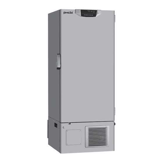
- Page 1 Operating Instructions Ultra-Low Temperature Freezer MDF-U55V Please read the operating instructions carefully before using this product, and keep the operating instructions for future use. See page 42 for model number.
-
Page 2: Table Of Contents
CONTENTS INTRODUCTION ···································································· 3 PRECAUTIONS FOR SAFE OPERATION ···································· 4 LABELS ON UNIT ··································································· 9 SYMBOLS ON UNIT ································································ 9 ENVIRONMENTAL CONDITIONS ·············································· 10 INTENDED USE AND PRECAUTIONS ········································ 10 FREEZER COMPONENTS Main body ········································································· 11 Control panel ····································································· 13 INSTALLATION SITE ·······························································... -
Page 3: Introduction
INTRODUCTION ■ Read the operating instructions carefully before using the product and follow the instructions for safe operation. ■ PHC Corporation takes no responsibility for safety if the product is not used as intended or is used with any procedures other than those given in the operating instructions. ■... -
Page 4: Precautions For Safe Operation
PRECAUTIONS FOR SAFE OPERATION It is imperative that the user complies with the operating instructions as they contain important safety advice. Items and procedures are described so that you can use this unit correctly and safely. Following these precautions will prevent possible injury to the user and any other person. - Page 5 PRECAUTIONS FOR SAFE OPERATION WARNING Do not use the unit outdoors. Exposure to rain may cause leakage and/or electric shock. Only qualified engineers or service personnel should install the unit. Installation by unqualified personnel may cause electric shock or fire. Install the unit in a location capable of bearing the total combined weight (product + optional accessories + stored items).
- Page 6 PRECAUTIONS FOR SAFE OPERATION WARNING When handling harmful samples (for example, those which consist of toxic, pathogenic or radioactive substances), install the unit inside a designated isolation facility. If the unit is installed in a location which is not an isolation facility, there may be detrimental effects on both people and the natural environment.
- Page 7 PRECAUTIONS FOR SAFE OPERATION WARNING Disconnect the power supply plug before moving the unit. Take care not to damage the power supply cord. A damaged power supply cord may cause electric shock or fire. Disconnect the power supply cord when the unit is not in use for long periods. Keeping the unit connected may cause electric shock, leakage, or fire due to the deterioration of insulation.
- Page 8 PRECAUTIONS FOR SAFE OPERATION CAUTION Never install the unit in a location where corrosive materials such as sulphur compounds are likely to be generated (e.g. near a drainage facility). Corrosion of the copper pipes may result in the deterioration and consequently the failure of the cooling unit. This unit must be plugged into a dedicated circuit protected by a branch circuit-breaker.
-
Page 9: Labels On Unit
LABELS ON UNIT <Labels applied to the unit> To avoid accidents, users are advised to read carefully the hazard labels found at key locations on the interior and exterior of the unit. Possible Warning/Caution Type Warning/Caution Label Description of Danger Danger Location of Danger Personal... -
Page 10: Environmental Conditions
ENVIRONMENTAL CONDITIONS This equipment is designed to be safe at least under the following conditions (based on the IEC 61010-1): ■ Indoor use; ■ Altitude up to 2000 m; ■ Ambient temperature 5 C to 40 ■ Maximum relative humidity 80 % for temperature up to 31 C decreasing linearly to 50 % relative humidity at 40 ■... -
Page 11: Freezer Components
FREEZER COMPONENTS Main body Outer door Magnetic door gasket Key hole 8 (inside) Power supply cord... - Page 12 FREEZER COMPONENTS 1. Control panel: The chamber temperature and other alarms/functions can be set using the keys on the control panel. The operational status can be checked on the temperature display and indicators [pages 13 and 14]. 2. Inner door: This prevents cold air from escaping when the outer door is opened. Always be sure to close the inner door securely before closing the outer door.
-
Page 13: Control Panel
FREEZER COMPONENTS Control panel 1. Temperature display: In normal operation, this displays the current chamber temperature. During temperature alarms, the display blinks [page 29]. When a self-diagnostic warning is triggered, a code is displayed here [page 30]. 2. Status monitor indicator (STATUS): The orange LED lamp lights up when the environmental condition or status deteriorates or when the unit is not operating normally. - Page 14 FREEZER COMPONENTS 7. Up arrow key ( ): During “temperature display mode”: pressing this key for more than 5 seconds activates the setting mode. During “setting mode”: pressing this key allows the (blinking) figure on the temperature display to be changed [pages 20 - 26]. The lock for the chamber temperature setting can also be set to ON or OFF by pressing this key [page 21].
-
Page 15: Installation Site
INSTALLATION SITE This unit must be installed in a location which meets all the conditions described below. If the unit is installed in a location which does not meet the conditions, its specified performance may not be achieved or malfunctions and accidents may occur. ■... -
Page 16: Installation
INSTALLATION When installing the unit, follow the steps below to secure the unit properly, and also be absolutely sure to earth the unit. In addition, install an earth leakage circuit breaker (on the unit’s power supply side), which is mandatory under the applicable laws and regulations. - Page 17 INSTALLATION 4. Preventing electric shock by earthing the unit When installing the unit, be absolutely sure to earth (ground) it. Earthing is necessary to prevent electric shocks resulting from deterioration of electrical insulations This unit comes with a 3-pin plug having one earth pin. Earthing work is not required in the case of a 3-pin power outlet equipped with an earth contact.
-
Page 18: Start-Up Procedure
START-UP PROCEDURE Follow this procedure for the initial operation of the unit and for consequent operations (after temporary stoppage for cleaning, maintenance or moving) . After a power failure, the unit will restart operation automatically with the same settings as before the power failure [page 19] 1. -
Page 19: During/After Power Failure
DURING/AFTER POWER FAILURE Display of chamber temperature during power failure By pressing the buzzer stop key (BUZZER) during a “power-failure alarm”, the buzzer stops and the chamber temperature is displayed on the temperature display for 5 seconds. Check the chamber temperature as appropriate by pressing the buzzer stop key (BUZZER) during power failure. -
Page 20: Setting The Chamber Temperature
SETTING THE CHAMBER TEMPERATURE Set the chamber temperature as required to keep the stored material at an appropriate temperature for a long period of time. Setting range of chamber temperature: between -90 C and -50 Initial setting (factory setting): -80 The guaranteed minimum chamber temperature is -86 C at an ambient temperature of 30 C with no... -
Page 21: Locking The Chamber Tempetaure Setting
LOCKING THE CHAMBER TEMPERATURE SETTING The chamber temperature setting can be locked to avoid accidental changes. When the lock is ON, a change of chamber temperature setting is not accepted even if the key on the control panel is operated. ... -
Page 22: Setting The Alarm Temperature
SETTING THE ALARM TEMPERATURE Setting the high-temperature alarm An abnormality (chamber temperature rise) is indicated by the alarm indicator, and the chamber temperature display blinking, and the buzzer sounding (15 minutes after blinking) if the chamber temperature exceeds the set value of the high-temperature alarm. Always set the high-temperature alarm to protect stored items from damage resulting from an increase in temperature. -
Page 23: Setting The Low-Temperature Alarm
SETTING THE ALARM TEMPERATURE Setting the low-temperature alarm An abnormality (chamber temperature drop) is indicated by the alarm indicator, and the chamber temperature display blinking, and the buzzer sounding (15 minutes after blinking) if the chamber temperature falls below the set value of low-temperature alarm. Always set the low-temperature alarm to protect stored items from damage resulting from a drop in temperature. -
Page 24: Setting The Buzzer Suspended Period
SETTING THE BUZZER SUSPENDED PERIOD An abnormality is indicated again by the buzzer sounding after a certain period has elapsed (the buzzer recovery time) if the alarm mode continues even after the buzzer has already been silenced by pressing the buzzer stop key (BUZZER). -
Page 25: Setting The Compressor Delay
SETTING THE COMPRESSOR DELAY The delay time before the compressor starts can be changed to reduce the load on the power line and to facilitate the start-up (reset) of the freezer during recovery after power failure. Setting range of delay time: between 3 and 15 minutes, in 1-minute intervals ... -
Page 26: Setting The Door Alarm Delay
SETTING THE DOOR ALARM DELAY The door check indicator lights up when the door is opened, and the buzzer sounds (after a delay) to indicate that the door is open. The delay time (between the lighting of the door check indicator and the activation of the buzzer) can be changed. -
Page 27: Remote Alarm Terminal
REMOTE ALARM TERMINAL The alarm is relayed to a remote location when a remote alarm device (commercially available) is connected to the remote alarm terminal. Installation of a remote alarm device is recommended when the unit is installed in an unattended location so that the operator of the unit is notified of the alarm. Contact our sales representative or agent to arrange the installation of a remote alarm device. -
Page 28: Monitoring The Freezer Status
MONITORING THE FREEZER STATUS The operational status of the freezer is monitored and the unit can provide an indication when its operational status is getting worse. Such an indication does not represent a failure of the unit. The status monitor indicator (STATUS) lights up when one of the conditions shown below is detected. To check the status, press the status key (STATUS). -
Page 29: Alarm Functions
ALARM FUNCTIONS This unit has the alarm functions listed below. When an alarm goes off, check the cause on the basis of the type of alarm generated, and take the necessary actions to deal with it without delay. Contact our sales representative or agent if the alarm is not resolved by eliminating the following causes. -
Page 30: Self-Diagnostic Functions
SELF-DIAGNOSTIC FUNCTIONS Alarms involving an error code indicated on the temperature display are generated by the unit’s self-diagnostic function. If any of the error codes are displayed, contact our sales representative or agent without delay, report the error code, and request repairs. Self-diagnostic Cause Indication... -
Page 31: Routine Maintenance
ROUTINE MAINTENANCE Cleaning the exterior, interior, and accessories Use a dry cloth to wipe down the outside and inside of the unit and all accessories. If the outside panels are dirty, clean them with a diluted neutral dish-washing detergent. Wipe off condensation from the exterior of the cabinet with a dry, soft cloth. Using an undiluted solution of detergent may cause the unit’s plastic areas to crack. -
Page 32: Defrosting The Chamber
ROUTINE MAINTENANCE Defrosting the chamber Frost may build up in the upper portion of the chamber and the inner door. Excessive accumulation of frost is likely to create gaps between the cabinet and the magnetic door gasket, which can reduce the cooling performance. -
Page 33: Replacement Of Worn-Out Parts
REPLACEMENT OF WORN-OUT PARTS Replacement of the battery for the power-failure alarm Replace the battery for the power-failure alarm every 3 years (when the battery indicator lights up) to ensure the alarm will operate in the event of a power failure. Contact our sales representative or agent to arrange the replacement of the battery when the battery indicator lights up. -
Page 34: Troubleshooting
TROUBLESHOOTING If the unit malfunctions, check out the following before calling for service. <Attention> If the malfunction is not resolved after checking the following items or if the malfunction is not shown in the table below, contact our sales representative or agent. Malfunction Check/Remedy Nothing operates even... -
Page 35: Disposal Of Unit
DISPOSAL OF UNIT Recycle of battery The unit contains a rechargeable battery. The battery is recyclable. At the end of its useful life, check with your local solid officials option or proper disposal. ■ Label indication is obliged to comply with Japanese battery regulation. 廢電池... - Page 36 DISPOSAL OF UNIT (English) Disposal of Old Equipment and Batteries Only for European Union and countries with recycling systems These symbols on the products, packaging, and/or accompanying documents mean that used electrical and electronic products and batteries must not be mixed with general household waste. For proper treatment, recovery and recycling of old products and used batteries, please take them to applicable collection points in accordance with your national legislation.
- Page 37 DISPOSAL OF UNIT (French) L’élimination des équipements et des batteries usagés Applicable uniquement dans les pays membres de l’Union européenne et les pays disposant de systèmes de recyclage. Apposé sur le produit lui-même, sur son emballage, ou figurant dans la documentation qui l’accompagne, ce pictogramme indique que les piles, appareils électriques et électroniques usagés, doivent être séparées des ordures ménagères.
- Page 38 DISPOSAL OF UNIT (Portuguese) Eliminação de Equipamentos Usados e Baterias Apenas para a União Europeia e países com sistemas de reciclagem Estes símbolos nos produtos, embalagens, e/ou documentos que os acompanham indicam que os produtos elétricos e eletrónicos e as baterias usados não podem ser misturados com os resíduos urbanos indiferenciados.
- Page 39 DISPOSAL OF UNIT (Dutch) Het ontdoen van oude apparatuur en batterijen. Enkel voor de Europese Unie en landen met recycle systemen. Deze symbolen op de producten, verpakkingen en/of begeleidende documenten betekenen dat gebruikte elektrische en elektronische producten en batterijen niet samen mogen worden weggegooid met de rest van het huishoudelijk afval.
-
Page 40: Optional Components
OPTIONAL COMPONENTS Temperature recorder The chamber temperature can be recorded and checked by installing an optional temperature recorder (MTR-G85C or MTR-85H). Contact our sales representative or agent to arrange purchase of the temperature recorder. Main specifications of temperature recorder MTR-G85C MTR-85H Recording range Between -100... -
Page 41: Specifications
SPECIFICATIONS Product name Ultra-Low Temperature Freezer MDF-U55V Medical purpose Storage of cells, organs, DNAs, plasma. External dimensions W770 mm x D870 mm x H1990 mm Internal dimensions W630 mm x D600 mm x H1380 mm Effective capacity 519 L Exterior... -
Page 42: Performance
PERFORMANCE Product name Ultra-Low Temperature Freezer MDF-U55V Model number MDF-U55V-PE Cooling performance C at the center of the chamber (ambient temperature: 30 C, no load)* Temperature control range C to -50 C (ambient temperature: 30 C, no load) Power source... -
Page 43: Safety Check Sheet
CAUTION Please fill in this form before servicing. Hand over this form to the service engineer to keep for his and your safety. Safety check sheet 1. Freezer contents : □ □ Risk of infection: □ □ Risk of toxicity: □... - Page 44 Original Operating Instructions < EU countries only > 0123 Nijverheidsweg 120 4879 AZ Etten Leur, The Netherlands Printed in Japan 1-1-1 Sakada, Oizumi-machi, Ora-gun, Gunma 370-0596, Japan LDCL030500-0 S0418-0 2018.04.01 © PHC Corporation 2018...
Need help?
Do you have a question about the MDF-U55V and is the answer not in the manual?
Questions and answers