Table of Contents
Advertisement
Quick Links
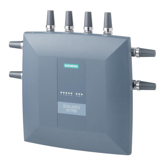
SCALANCE W1788-x / W1748-1
SIMATIC NET
Industrial Wireless LAN
SCALANCE W1788-x / W1748-1
Operating Instructions
03/2022
C79000-G8976-C484-05
Introduction
Safety notices
Security
recommendations
Description of the device
Installation and removal
Connection
Maintenance and cleaning
Troubleshooting
Technical specifications
Dimension drawings
Approvals
1
2
3
4
5
6
7
8
9
10
11
Advertisement
Table of Contents

Subscribe to Our Youtube Channel
Related Manuals for Siemens SIMATIC NET SCALANCE W1788 Series


Summary of Contents for Siemens SIMATIC NET SCALANCE W1788 Series
- Page 1 SCALANCE W1788-x / W1748-1 Introduction Safety notices Security SIMATIC NET recommendations Description of the device Industrial Wireless LAN SCALANCE W1788-x / W1748-1 Installation and removal Connection Operating Instructions Maintenance and cleaning Troubleshooting Technical specifications Dimension drawings Approvals 03/2022 C79000-G8976-C484-05...
- Page 2 Note the following: WARNING Siemens products may only be used for the applications described in the catalog and in the relevant technical documentation. If products and components from other manufacturers are used, these must be recommended or approved by Siemens. Proper transport, storage, installation, assembly, commissioning, operation and maintenance are required to ensure that the products operate safely and without any problems.
-
Page 3: Table Of Contents
Table of contents Introduction ............................. 5 Safety notices ............................9 Security recommendations ........................11 Description of the device ........................19 Structure of the type designation ....................19 Device views ..........................20 4.2.1 SCALANCE W1788-1 / W1748-1 ....................20 4.2.2 SCALANCE W1788-2 ........................21 4.2.3 SCALANCE W1788-2IA ........................ - Page 4 Table of contents Antenna ............................67 Grounding ............................70 Replacing a CLP ..........................72 Maintenance and cleaning ........................75 Troubleshooting ............................ 77 Downloading new firmware using TFTP without WBM and CLI ........... 77 Restoring the factory settings ..................... 78 Technical specifications........................81 SCALANCE W1788-1 / W1748-1 ....................
-
Page 5: Introduction
Documentation on the Internet You can find the current version of the document on the Internet at (https://support.industry.siemens.com/cs/de/en/ps/15859/man) Enter the name or article number of the product in the search filter. Documentation on configuration... - Page 6 Firmware The firmware is signed and encrypted. This ensures that only firmware created by Siemens can be downloaded to the device. The firmware is available on the Internet pages of the Siemens Industry Online Support: (https://support.industry.siemens.com/cs/ww/en/ps/25169/dl) Note on firmware/software support Check regularly for new firmware/software versions or security updates and apply them.
- Page 7 (https://support.industry.siemens.com/cs/ww/en/view/109479891)). Note the different national regulations. Device defective If a fault develops, send the device to your SIEMENS representative for repair. Repairs on-site are not possible. Trademarks The following and possibly other names not identified by the registered trademark sign ®...
- Page 8 Introduction SCALANCE W1788-x / W1748-1 Operating Instructions, 03/2022, C79000-G8976-C484-05...
-
Page 9: Safety Notices
Safety notices CAUTION To prevent injury and damage, read the manual before using the device. Read the safety notices Note the following safety notices. These relate to the entire working life of the device. You should also read the safety notices relating to handling in the individual sections, particularly in the sections "Installation"... - Page 10 Safety notices SCALANCE W1788-x / W1748-1 Operating Instructions, 03/2022, C79000-G8976-C484-05...
-
Page 11: Security Recommendations
OpenVPN). • Separate connections correctly (WBM, Telnet, SSH etc.). • Check the user documentation of other Siemens products that are used together with the device for additional security recommendations. • Using remote logging, ensure that the system protocols are forwarded to a central logging server. - Page 12 Security recommendations • Replace the default passwords for all user accounts, access modes and applications (if applicable) before you use the device. • Define rules for the assignment of passwords. • Use passwords with a high password strength. Avoid weak passwords, (e.g. password1, 123456789, abcdefgh) or recurring characters (e.g.
- Page 13 • Verify certificates based on the fingerprint on the server and client side to prevent "man in the middle" attacks. Use a second, secure transmission path for this. • Before sending the device to Siemens for repair, replace the current certificates and keys with temporary disposable certificates and keys, which can be destroyed when the device is returned.
- Page 14 Initialization Vector Implementation Information Disclosure Vulnerability (for example, BEAST). • Ensure that the latest firmware version is installed, including all security-related patches. You can find the latest information on security patches for Siemens products at the Industrial Security (https://www.siemens.com/industrialsecurity) or ProductCERT Security Advisories (https://www.siemens.com/cert/en/cert-security-advisories.htm) website.
- Page 15 Security recommendations Secure/ non-secure protocols • Use secure protocols if access to the device is not prevented by physical protection measures. • Disable or restrict the use of non-secure protocols. While some protocols are secure (e.g. HTTPS, SSH, 802.1X, etc.), others were not designed for the purpose of securing applications (e.g.
- Page 16 Security recommendations List of available services The following is a list of all available services and their ports through which the device can be accessed. The table includes the following columns: • Service The services that the device supports • Default port status This is the status of the port in the delivery state (factory setting).
- Page 17 Security recommendations Service Protocol / Port Default port Configurable Authentication Encryption number status Port Service DHCP Client IPv4 UDP/68 Outgoing only ✓ DHCP Client IPv6 UDP/546 Outgoing only ✓ DHCP Server UDP/67 Closed ✓ DNS Client TCP/53 Outgoing only ✓ UDP/53 EthernetIP TCP/44818...
- Page 18 Security recommendations The following is a list of all available Layer 2 services through which the device can be accessed. The table includes the following columns: • Layer 2 service The Layer 2 services that the device supports. • Default status The default status of the service (open or closed).
-
Page 19: Description Of The Device
Description of the device Structure of the type designation Structure of the type designation The type designation of the device is made up of several parts that have the following meaning: SCALANCE W1788-x / W1748-1 Operating Instructions, 03/2022, C79000-G8976-C484-05... -
Page 20: Device Views
Description of the device 4.2 Device views Device views 4.2.1 SCALANCE W1788-1 / W1748-1 ① Ground connector (thread M4) on the top ② R1 antenna port, female N-Connect type Two connectors on the top and one each on the right and left side ③... -
Page 21: Scalance W1788-2
Description of the device 4.2 Device views 4.2.2 SCALANCE W1788-2 ① Ground connector (thread M4) on the top ② R1 antenna port, female N-Connect type Two connectors on the top and one each on the right and left side ③ R2 antenna port, female N-Connect type Two connectors on the top and one each on the right and left side ④... -
Page 22: Scalance W1788-2Ia
Description of the device 4.2 Device views 4.2.3 SCALANCE W1788-2IA ① Ground connector (thread M4) on the top ② Ground connector (thread M4) on the bottom, covered ③ Connector for power supply (L1, L2), covered ④ Ethernet connector P2 (PoE capability), covered ⑤... -
Page 23: Components Of The Product
Accessories (Page 24). Please check that the consignment you have received is complete. If the consignment is incomplete, contact your supplier or your local Siemens office. SCALANCE W1788-x / W1748-1 Operating Instructions, 03/2022, C79000-G8976-C484-05... -
Page 24: Accessories
Description of the device 4.4 Accessories Accessories Technical data subject to change. You will find further information on the range of accessories in the Industry Mall (https://mall.industry.siemens.com/mall/en/WW/Catalog/Products/10021486) Use the TIA Selection Tool (https://mall.industry.siemens.com/tst/) for configuring the device. 4.4.1 Installation Component Description... - Page 25 Description of the device 4.4 Accessories Cables Industrial Ethernet (pre-assembled) Component Description Article number IE TP Cord M12-180/M12- IE Flexible Cable with two M12 plugs (X-coded) Length 0.3m 6XV1878-5HE30 Length 0.5m 6XV1878-5HE50 Length 1m 6XV1878-5HH10 Length 1.5m 6XV1878-5HH15 Length 2m 6XV1878-5HH20 Length 3m 6XV1878-5HH30...
-
Page 26: Power Supply
CONNECTOR 4.4.5 Flexible connecting cables, antennas and accessories You will find an overview of the IWLAN products and their accessories in the Order overview (https://support.industry.siemens.com/cs/ww/en/view/109766333). 4.4.5.1 Flexible connecting cables Flexible connecting cable N-Connect/R-SMA Flexible connecting cable for connecting an antenna to a SCALANCE W device with R-... - Page 27 Description of the device 4.4 Accessories For railway applications, the following connecting cable are available: Length Article number 6XV1875-5TH10 6XV1875-5TH20 6XV1875-5TH50 Flexible connecting cable N-Connect/N-Connect Flexible connecting cable for connecting an antenna to a SCALANCE W device with N- Connect connectors, preassembled with two N-male connectors: Length Article number 6XV1875-5AH10...
-
Page 28: Lightning Protection
When you select an antenna, keep in mind the national approvals for your device. You will find more detailed information in Wireless approvals (https://www.siemens.com/wireless-approvals). The SCALANCE W1788-2IA uses internal omni antennas (7 dBi at 2.4 GHz and 5 dBi at 5 GHz). - Page 29 Description of the device 4.4 Accessories Antennas Type Properties Article number ANT792-4DN RCoax helical antenna, circular 6GK5792-4DN00-0AA6 polarization, 4 dBi, 2.4 GHz, N-Connect female. ANT792-6MN Omni antenna, mast/wall mounting, 6 dBi 6GK5792-6MN00-0AA6 2.4 GHz, N-Connect female ANT792-8DN Directional antenna, mast/wall mounting, 6GK5792-8DN00-0AA6 14 dBi 2.4 GHz, N-Connect female ANT793-6DG...
-
Page 30: Led Display
Description of the device 4.5 LED display LED display 4.5.1 SCALANCE W1788-1 / W1748-1 Information on operating status and data transfer On the front of the housing, several LEDs provide information on the operating status of the device: Color Meaning Power supply L1 too low. - Page 31 Description of the device 4.5 LED display Color Meaning The device is not supplied using PoE. Green The device is supplied using PoE. There is no connection over the Ethernet port P1. Green There is a connection over the Ethernet port P1 (link). Flashing green and Data transfer over the Ethernet interface P1.
- Page 32 Description of the device 4.5 LED display Color Meaning Flashing green and Data transfer via the WLAN interface 1. yellow Access point mode: Flashing yellow With DFS (802.11h), the channel is scanned for one minute for competing radar signals before the channel can be used for data traffic.
-
Page 33: Scalance W1788-2 / W1788-2Ia
Description of the device 4.5 LED display Note Primary user (radar) on all enabled channels If the device detects competing radar signals on all enabled channels of the WLAN interface, the F LED is lit and R1 flash. No data traffic is then possible for the next 30 minutes. - Page 34 Description of the device 4.5 LED display Color Meaning Power supply L1 too low. Green Power supply L1 is applied. Power supply L2 too low. Green Power supply L2 is applied. The device is not supplied using PoE. Green The device is supplied using PoE. There is no connection over the Ethernet port P1.
- Page 35 Description of the device 4.5 LED display Color Meaning The WLAN interface 1 is deactivated. Access point mode: Green The WLAN interface 1 is initialized and ready for operation. Client mode: There is a connection over the WLAN interface 1. Client mode: Flashing green The client is searching for a connection to an access point.
- Page 36 Description of the device 4.5 LED display Color Meaning No fault/error. The device is starting up or an error has occurred. Flashing red The bootloader waits in this state for a new firmware file that you can download by TFTP. Interval: 500 ms on / 500 ms off Flashing red...
-
Page 37: Reset Button
Description of the device 4.6 Reset button Reset button Position NOTICE Loss of water and dust protection If the cover is not mounted correctly, the device is not water and dust proof. The Reset button ① is located behind the screw-down cover on the underside of the housing. -
Page 38: Configuration License Plug
Description of the device 4.7 Configuration License PLUG NOTICE Previous settings If you reset, all the changes you have made will be overwritten by factory defaults. NOTICE Inadvertent reset An inadvertent reset can cause disturbances and failures in a configured network with further consequences. - Page 39 – The configuration data of the device is stored in a secured memory area of the CLP. This secured memory area can only be accessed via the authentication of the Siemens device. – The device checks whether a CLP is inserted at one second intervals. If the device detects that the CLP has been removed, it restarts automatically.
- Page 40 Description of the device 4.7 Configuration License PLUG SCALANCE W1788-x / W1748-1 Operating Instructions, 03/2022, C79000-G8976-C484-05...
-
Page 41: Installation And Removal
Installation and removal Safety notices for installation Safety notices When installing the device, keep to the safety notices listed below. NOTICE Improper mounting Improper mounting may damage the device or impair its operation. • Before mounting the device, always ensure that there is no visible damage to the device. - Page 42 Installation and removal 5.1 Safety notices for installation WARNING If the device is installed in a cabinet, the inner temperature of the cabinet corresponds to the ambient temperature of the device. WARNING The device is intended for indoor use only. Safety notices on use in hazardous areas General safety notices relating to protection against explosion WARNING...
- Page 43 Installation and removal 5.1 Safety notices for installation Safety notices when using according to FM If you use the device under FM conditions you must also keep to the following safety notices in addition to the general safety notices for protection against explosion: WARNING EXPLOSION HAZARD The equipment is intended to be installed within an enclosure/control cabinet.
-
Page 44: Types Of Installation
Installation and removal 5.2 Types of installation Types of installation Note The device is only approved for operation in closed rooms. Note the following environmental conditions. Antennas, in particular directional antennas, must be mounted in keeping with their characteristics (refer to the technical specifications of the antenna --> Radiation pattern diagrams). -
Page 45: Wall Mounting
Installation and removal 5.3 Wall mounting Wall mounting The wall mounting kit for wall mounting is not included with the product, see accessories. (Page 24) Installation 1. Unscrew the bracket pre-installed at the factory for securing to a DIN rail from the device and remove it SCALANCE W1788-x / W1748-1 Operating Instructions, 03/2022, C79000-G8976-C484-05... - Page 46 Installation and removal 5.3 Wall mounting 2. Prepare the four drill holes for wall mounting. For the precise dimensions, refer to the section "Dimension drawings (Page 87)". Secure the mounting plate to the wall with four screws . Note the direction of the holding plate ("TOP").
- Page 47 Installation and removal 5.3 Wall mounting 3. Screw the self-tapping M3 head screws into the device as far as they will go. The tightening torque is 1.2 Nm. SCALANCE W1788-x / W1748-1 Operating Instructions, 03/2022, C79000-G8976-C484-05...
- Page 48 Installation and removal 5.3 Wall mounting 4. Insert the device with the screwed-in head screws into the four key-hole brackets of the mounting plate . Make sure that the head screws are correctly positioned in the key-hole brackets. 5. Pull the inserted device down until it sits firmly in the key-hole brackets.
-
Page 49: Installing On A Din Rail
Installation and removal 5.4 Installing on a DIN rail Installing on a DIN rail The bracket for securing to a DIN rail is pre-installed on the device in the factory settings. ① Bracket for securing to a DIN rail SCALANCE W1788-x / W1748-1 Operating Instructions, 03/2022, C79000-G8976-C484-05... - Page 50 Installation and removal 5.4 Installing on a DIN rail Installation 1. Place the device on the upper edge of the DIN rail 2. Press the device against the DIN rail until the DIN rail slider catch locks in place 3. Connect the power supply, refer to the section "Power supply (Page 63)". 4.
- Page 51 Installation and removal 5.4 Installing on a DIN rail Uninstalling 1. Turn off the power to the device. 2. Disconnect all connected cables. 3. Pull the bracket down with a screwdriver 4. Swivel the device away from the DIN rail and remove it from the DIN rail.
-
Page 52: Installing On A Standard Rail
Installation and removal 5.5 Installing on a standard rail Installing on a standard rail The mounting adapters and the corresponding screws are not supplied with the product; see "Accessories" (Page 24). Installation 1. Unscrew the bracket pre-installed at the factory for securing to a DIN rail from the device and remove it SCALANCE W1788-x / W1748-1 Operating Instructions, 03/2022, C79000-G8976-C484-05... - Page 53 Installation and removal 5.5 Installing on a standard rail 2. Secure the two mounting adapters with one M4 countersunk screw each to the device . The tightening torque is 1.8 Nm. SCALANCE W1788-x / W1748-1 Operating Instructions, 03/2022, C79000-G8976-C484-05...
- Page 54 Installation and removal 5.5 Installing on a standard rail 3. Place the device on the upper edge of the corresponding mounting rail – ① S7-300 standard rail – ② S7-1500 standard rail 4. Swing the device to the standard rail 5.
- Page 55 Installation and removal 5.5 Installing on a standard rail Uninstalling 1. Turn off the power to the device. 2. Disconnect all connected cables. 3. Loosen the screws of the mounting adapters completely from the standard rail. 4. Remove the device from the standard rail. 5.
- Page 56 Installation and removal 5.5 Installing on a standard rail SCALANCE W1788-x / W1748-1 Operating Instructions, 03/2022, C79000-G8976-C484-05...
-
Page 57: Connection
Connection Safety when connecting up Safety notices When connecting up the device, keep to the safety notices listed below. Note Close unused sockets Close all unused M12 sockets with protective caps (tightening torque at least 0.4 Nm) to achieve the specified type of protection. Note Strain relief for the Ethernet cables In order to avoid mechanical stress on the Ethernet cables and resulting interruption of... - Page 58 Connection 6.1 Safety when connecting up WARNING Danger due to lightning strikes Installing this lightning protector between an antenna and a SCALANCE W device is not adequate protection against a lightning strike. The LP798-1N lightening protector only works within the framework of a comprehensive lightning protection concept. If you have questions, ask a qualified specialist company.
- Page 59 Connection 6.1 Safety when connecting up NOTICE Damage to the device due to potential differences To fully eliminate the influence of electromagnetic interference, the device must be grounded. There must be no potential difference between the following parts, otherwise the device or other connected device could be severely damaged: •...
- Page 60 Connection 6.1 Safety when connecting up WARNING Lack of equipotential bonding If there is no equipotential bonding in hazardous areas, there is a risk of explosion due to equalizing current or ignition sparks. • Ensure that equipotential bonding is available for the device. WARNING Unprotected cable ends There is a risk of explosion due to unprotected cable ends in hazardous areas.
- Page 61 Connection 6.1 Safety when connecting up Notes for use in hazardous locations according to ATEX, IECEx, UKEX and CCC Ex If you use the device under ATEX, IECEx, UKEX or CCC Ex conditions you must also keep to the following safety instructions in addition to the general safety instructions for protection against explosion: WARNING Transient overvoltages...
- Page 62 Connection 6.1 Safety when connecting up Safety information when using in accordance with UL 61010-2-201 If you use the device under UL 61010-2-201 conditions you must also keep to the following safety notices in addition to the general safety notices for protection against explosion: NOTICE Suitable fusing for the power supply cable...
-
Page 63: Power Supply
Connection 6.2 Power supply Power supply Note Galvanic isolation of the power supply unit To ensure dielectric strength according to IEEE 802.3, the supplying 24 V power supply unit must be galvanically isolated with a dielectric strength of 1500 VAC. The galvanic isolation must also not be bridged by other devices connected to the same power supply unit. - Page 64 Connection 6.2 Power supply Position and pin assignment ① M12 interface, direct feed in, A-coded, 4-pin ② M12 Ethernet port P2 LAN PoE, X-coded, 8-pin The power can also be supplied via this interface (Power over Ethernet). Pin assignment, see Ethernet (Page 66) ③...
- Page 65 Connection 6.2 Power supply Power over Ethernet (PoE) With PoE, the power for networked devices is carried via Ethernet. • Mode A (Gigabit Ethernet) Power is transferred on the data wires 1, 2, 3 and 6 of the Ethernet cable. •...
-
Page 66: Ethernet
Connection 6.3 Ethernet Ethernet For connection to Industrial Ethernet at 10/100/1000 Mbps, the devices have the following two M12 interfaces: X-coded, 8-pin. Position and pin assignment ① M12 interface P1 LAN ② M12 interface P2 LAN PoE The power can also be supplied via this interface (Power over Ethernet). The eight-pin connection socket has the following pin assignment: Assignment Connecting Ethernet ports... -
Page 67: Antenna
Connection 6.4 Antenna Antenna SCALANCE W1788-1/W1748-1 The SCALANCE W1788-1/ W1748-1 has four antenna connectors of the type N- Connector female. ① R1 A2 ③ R1 A4 ② R1 A3 ④ R1 A1 (covered) SCALANCE W1788-x / W1748-1 Operating Instructions, 03/2022, C79000-G8976-C484-05... - Page 68 Connection 6.4 Antenna SCALANCE W1788-2 The SCALANCE W71788-2 has 8 antenna connectors of the type N-Connect female. ① R1 A2 ⑤ R1 A4 ② R2 A2 ⑥ R2 A4 ③ R1 A3 ⑦ R1 A1 (covered) ④ R2 A3 ⑧ R2 A1 (covered) SCALANCE W1788-x / W1748-1 Operating Instructions, 03/2022, C79000-G8976-C484-05...
- Page 69 Connection 6.4 Antenna Procedure Follow the steps below to connect a cable for an external antenna: 1. Remove the protective cap from the affected N-Connect on the device. Note Keep the protective caps Keep the protective caps removed for later use. 2.
-
Page 70: Grounding
Connection 6.5 Grounding NOTICE UL approval only for use in buildings Within the area of authority of the NEC and CEC, the SCALANCE W1788/W1748 devices and the antennas connected to them may only be used in a closed building. For this reason, do not lead antennas into the outdoor area if you need to meet UL or CSA requirements. - Page 71 Connection 6.5 Grounding Connecting up functional ground Follow the steps below to connect the functional ground: 1. Put the toothed washer ①, the grounding terminal ② and the screw ③ together as shown in the drawing. ① Toothed washer ② Grounding terminal with cable ③...
-
Page 72: Replacing A Clp
Connection 6.6 Replacing a CLP Replacing a CLP Position The PLUG slot is on the bottom of the device housing under a cover, see Reset button (Page 19). ① ② Slot cover ③ M3 screws (Torx T10) Removing a CLP Note Loss of the configuration The reset button is located directly beside the slot for the CLP. - Page 73 Connection 6.6 Replacing a CLP 3. To release the CLP ①, insert a screwdriver between the front edge of the CLP (A) and the slot. 4. Remove the CLP from the slot. 5. Close the slot cover (torque 0.8 Nm) to ensure that the device maintains the degree of protection IP65.
- Page 74 Connection 6.6 Replacing a CLP SCALANCE W1788-x / W1748-1 Operating Instructions, 03/2022, C79000-G8976-C484-05...
-
Page 75: Maintenance And Cleaning
Maintenance and cleaning WARNING Unauthorized repair of devices in explosion-proof design Risk of explosion in hazardous areas • Repair work may only be performed by personnel authorized by Siemens. WARNING Impermissible accessories and spare parts Risk of explosion in hazardous areas •... - Page 76 Maintenance and cleaning SCALANCE W1788-x / W1748-1 Operating Instructions, 03/2022, C79000-G8976-C484-05...
-
Page 77: Troubleshooting
Firmware The firmware is signed and encrypted. This ensures that only firmware created by Siemens can be downloaded to the device. You can download new firmware to the device using TFTP. To do this, the device does not need to be reachable either using Web Based Management (WBM) or using the Command Line Interface (CLI). -
Page 78: Restoring The Factory Settings
Troubleshooting 8.2 Restoring the factory settings Restoring the factory settings NOTICE Previous settings If you reset, all the settings you have made will be overwritten by factory defaults. NOTICE Inadvertent reset An inadvertent reset can cause disturbances and failures in a configured network with further consequences. - Page 79 Troubleshooting 8.2 Restoring the factory settings Via the configuration You will find detailed information on resetting the device parameters using the WBM and CLI in the configuration manuals: • Web Based Management, section "Restart" • Command Line Interface, section "Reset and Defaults" SCALANCE W1788-x / W1748-1 Operating Instructions, 03/2022, C79000-G8976-C484-05...
- Page 80 Troubleshooting 8.2 Restoring the factory settings SCALANCE W1788-x / W1748-1 Operating Instructions, 03/2022, C79000-G8976-C484-05...
-
Page 81: Technical Specifications
SCALANCE W1788-1 / W1748-1 Note You will find detailed information on the transmit power and receiver sensitivity in the document "Performance data 802.11ac SCALANCE W1700" on the Internet at (https://support.industry.siemens.com/cs/de/en/view/109759606). • SCALANCE W1788-1 M12 • SCALANCE W1748-1 M12 Technical specifications... - Page 82 Technical specifications 9.1 SCALANCE W1788-1 / W1748-1 Technical specifications Radio Antenna connector Quantity Design N-Connect socket Impedance 50 Ω nominal Frequency range 2412 ... 2480 MHz 4920 ... 5875 MHz Electrical data Direct 24 VDC supply Supply voltage from socket 24 V DC Safe Extra Low Voltage (SELV) Type of current Permitted range...
-
Page 83: Scalance W1788-2 / W1788-2Ia
SCALANCE W1788-2 / W1788-2IA Note You will find detailed information on the transmit power and receiver sensitivity in the document "Performance data 802.11ac SCALANCE W1700" on the Internet at (https://support.industry.siemens.com/cs/de/en/view/109759606). • SCALANCE W1788-2 M12 • SCALANCE W1788-2 M12 EEC • SCALANCE W1788-2IA M12... - Page 84 Technical specifications 9.2 SCALANCE W1788-2 / W1788-2IA Technical specifications Permitted cable lengths (Alternative combinations per length range) (Ethernet) IE TP torsion cable 0 ... 55 m 0 ... 45 m + 10 m TP cord IE FC TP marine cable 0 ...
- Page 85 Technical specifications 9.2 SCALANCE W1788-2 / W1788-2IA Technical specifications Permitted ambient conditions Ambient temperature During operation Non EEC variant -20 ℃ to +70 ℃ EEC variant -40 °C ...+75 °C During storage -40 ℃ to +85 ℃ During transportation -40 ℃ to +85 ℃ Relative humidity During operation ≤...
- Page 86 Technical specifications 9.2 SCALANCE W1788-2 / W1788-2IA SCALANCE W1788-x / W1748-1 Operating Instructions, 03/2022, C79000-G8976-C484-05...
-
Page 87: Dimension Drawings
Dimension drawings 10.1 SCALANCE W1788-x / W1748-1 Note Dimensions are specified in mm. Front view Side view SCALANCE W1788-x / W1748-1 Operating Instructions, 03/2022, C79000-G8976-C484-05... -
Page 88: Mounting Plate
Dimension drawings 10.2 Mounting plate 10.2 Mounting plate Drill holes for wall mounting SCALANCE W1788-x / W1748-1 Operating Instructions, 03/2022, C79000-G8976-C484-05... -
Page 89: Approvals
Approvals You will find the approvals of the products in the reference document "Approvals SCALANCE W1700 802.11ac" on the Internet pages of Siemens Industry Online Support: • Using the search function at Industrial communication (https://support.industry.siemens.com/cs/ww/en/ps/15859/cert) • Using the search function at Siemens Industry Online Support (https://support.industry.siemens.com/cs/ww/en/) - Page 90 Approvals SCALANCE W1788-x / W1748-1 Operating Instructions, 03/2022, C79000-G8976-C484-05...
-
Page 91: Index
Index Accessories, 24 Installation A-coded, 63 DIN rail, 49 Antenna cables, 26 S7-1500 standard rail, 52 Antennas, 26, 67 S7-300 standard rail, 52 Wall mounting, 45 Interfaces, 81, 83 Cables Permitted lengths, 81, 83 CLP, 38 LED display, 30, 33 Function, 39 Lightning protection, 57 Replacing, 72...
Need help?
Do you have a question about the SIMATIC NET SCALANCE W1788 Series and is the answer not in the manual?
Questions and answers