Table of Contents
Advertisement
Advertisement
Table of Contents

Related Manuals for Aruba 9240


Summary of Contents for Aruba 9240
- Page 1 Aruba 9240 Gateway...
- Page 2 Hewlett Packard Enterprise Company. To obtain such source code, send a check or money order in the amount of US $10.00 to: Hewlett Packard Enterprise Company Attn: General Counsel 6280 America Center Drive San Jose, CA 95002 Aruba 9240 Gateway | Installation Guide 0512230-01 | April 2022...
-
Page 3: Table Of Contents
Guide Overview .....................5 Related Documentation ..................5 Contacting Support ....................5 Chapter 1 9240 Gateway................... 6 Package Checklist ....................6 9240 Gateway Components .................6 SFP28 Ports ....................8 SFP28 Port LEDs..................8 Power, Status, and Peered LEDs..............9 LCD Panel .......................9 LCD Mode Menu ..................9 Disabling the LCD Screen ..............10 USB Type-C Console Port ................11... - Page 4 Canada......................26 EU Regulatory Conformance ................26 UKCA ......................27 Battery Statements ..................27 Russia ......................28 Kazakhstan....................28 Proper Disposal of Aruba Equipment ..............28 Waste of Electrical and Electronic Equipment ..........28 European Union RoHS ..................29 India RoHS ....................29 China RoHS ....................29 | Installation Guide Aruba 9240 Gateway...
-
Page 5: Preface
Preface This document describes the hardware features of the Aruba 9240 Gateway. It provides a detailed overview of the physical and performance characteristics of each gateway model and explains how to install the gateway and its accessories. Guide Overview Chapter 1, “9240 Gateway” on page 6 provides a detailed hardware overview of the 9240 gateway ... -
Page 6: 9240 Gateway
Power Cable USB Type-C Console Cable Rubber Feet Optional accessories are available for use with the Aruba 9240 Series and are sold separately. Contact your Aruba sales representative for details and assistance. 9240 Gateway Components This section introduces the different component and its location in the Aruba 9240 gateway. - Page 7 USB3.0 Interfaces 2 x USB3.0 interfaces. USB storage device can be used to save and upload configurations Power, Status, and Peered LEDs Used for basic monitoring of the Aruba 9240 gateway Used to configure LED behavior and other basic operations...
-
Page 8: Sfp28 Ports
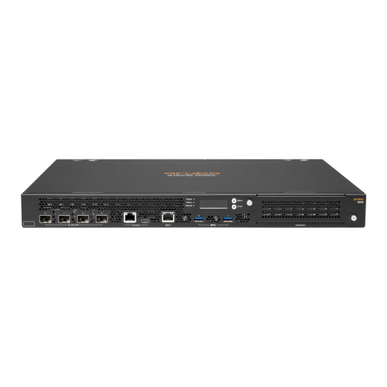
Slot for additional power supply module SFP28 Ports The 9240 is equipped with four SFP28 1G/10G/25G data ports. These ports are labeled as 0, 1, 2 and 3. These ports are intended for use with Aruba supported SFP/SFP+/SFP28 modules.The ports support three speed (1G, 10G, or 25G) operation. -
Page 9: Power, Status, And Peered Leds
Reserved for future use LCD Panel The Aruba 9240 gateway is equipped with an LCD panel that displays information about the gateway’s status and provides a menu that allows basic operations such as initial setup and reboot. The LCD panel displays two lines of text with a maximum of 16 characters on each line. When using the LCD panel, the active line is indicated by an arrow next to the first letter. -
Page 10: Disabling The Lcd Screen
Exit Maintenance menu Disabling the LCD Screen By default, the LCD screen is enabled. However, if the 9240 is deployed in a location without physical security, the LCD screen can be disabled through the CLI. When disabled, pushing one of the navigation buttons will only illuminate the screen and display the slot, role, device name, and any alarms. -
Page 11: Usb Type-C Console Port
USB Type-C Console Port The 9240 is equipped with one USB type-C console port that provides console access for direct local access. If both USB and RJ-45 console ports are connected, the USB connection takes precedence over the RJ-45 console connection. -
Page 12: Serial Console Port Adapter
10/100 Mbps USB Interface The 9240 is equipped with two USB 3.0 interface. A USB storage device can be used to save and upload configurations to the gateway. USB functions are controlled through the LCD panel on the front of the gateway. For more information on the LCD panel and its functions, see “LCD Panel”... -
Page 13: Fan Module
Load Sharing Load sharing occurs when more than one power supply of the same rating is installed in the 9240 gateway and turned on. Load sharing divides the total power load of the gateway among all available power supplies. Since the power supplies work together, the effective power capacity of the gateway is increased with each additional power supply. -
Page 14: Led Indicators
PSU Slot 1 The 9240 gateway includes a PSU slot 1 that has a filler panel covering the opening. PSU slot 1 is for an additional power supply module that may be required for redundancy. PSU slot 1 can hold the same power supply module as PSU slot 0. -
Page 15: Installation
This chapter describes how to install an Aruba 9240 gateway using available mounting options. The 9240 ships with an accessory kit that includes the equipment needed to install the gateway in standard, 19-inch telco rack. Additional mounting options are sold separately. -
Page 16: Selecting A Location
Limited electromagnetic interference For best operation, keep the 9240 gateway and all cords and cables at least 0.7 meters (2.3 feet) from fluorescent lighting fixtures, and 2 meters (6.6 feet) from photocopiers, radio transmitters, electric generators, and other sources of strong electromagnetic interference. -
Page 17: Installation Steps
Suitable Screwdrivers for all screw types provided in the box (not included in the kit) Some racks require screws that differ from those included with the 9240 gateway. Ensure that you have the correct screws before installing the 9240 gateway. -
Page 18: Rack Mount Installation - Mid
Suitable Screwdrivers for all screw types provided in the box (not included in the kit) Some racks require screws that differ from those included with the 9240 gateway. Ensure that you have the correct screws before installing the 9240 gateway. -
Page 19: Required Tools And Equipment
Leave additional space in the front and the back of the gateway to access network cables, LED status indicators, and power cord. Table or Shelf Installation This mounting option allows mounting the 9240 gateway on a table or shelf. Required Tools and Equipment Rubber Feet (included in the kit) ... -
Page 20: Connecting And Disconnecting The Ac Power Cord
Connecting and Disconnecting the AC Power Cord Once you have installed the 9240 gateway, you are ready to power on the device. The 9240 gateway is not equipped with an On/Off switch. The device will power on when the AC power cord is connected to the power supply module and an AC power outlet. -
Page 21: Installing And Removing A Fan Module
2. Pull the AC power cord from the power supply module. The 9240 gateway is now turned Off. Shock hazard. Disconnect both power supplies to remove all power. Installing and Removing a Fan Module Use standard ESD precautions when installing or removing a fan module. -
Page 22: Installing And Removing A Power Supply
The power supply module is hot-swappable when two power supplies are installed. Hot swapping allows you to replace a failed power supply without powering down the 9240 gateway during the replacement process. This makes it unnecessary to shut down the 9240 gateway during the installation procedure. -
Page 23: Removing An Ac Power Supply
Use standard ESD precautions when installing or removing an SFP28. Installing an SFP28 module To install an SFP28 module into the 9240 gateway, slide the SFP28 module, top side facing upward, into a corresponding SFP28 port until a connection is made and an audible click is heard (see Figure 13). -
Page 24: Disconnecting An Lc Cable
Disconnecting an LC Cable To disconnect an LC fiber optic cable from an SFP28 module, depress the transceiver handle to release the latch on the cable and simultaneously pull the cable out of the port. | Installation | Installation Guide Aruba 9240 Gateway... -
Page 25: Chapter 3 Specifications, Safety, And Compliance
The regulatory model name for the 9240 gateway is ARCN9240. Safety and Regulatory Compliance Aruba gateways must be installed by a professional installer. The professional installer is responsible for ensuring that grounding is available and it meets applicable local and national electrical codes. -
Page 26: Canada
undesired operation. Changes or modifications to this unit not expressly approved by Aruba, a Hewlett Packard Enterprise company, can void the user’s authority to operate this equipment. This equipment has been tested and found to comply with the limits for a Class A digital device, pursuant to Part 15 of the FCC Rules. -
Page 27: Ukca
There is a risk of explosion if battery is replaced by an incorrect type, so dispose used batteries according to the instructions. Japan VCCI Korea Taiwan | Installation Guide Specifications, Safety, and Compliance | Aruba 9240 Gateway... -
Page 28: Russia
Proper Disposal of Aruba Equipment Waste of Electrical and Electronic Equipment Aruba, a Hewlett Packard Enterprise company products at end of life are subject to separate collection and treatment in the EU Member States, Norway, and Switzerland and therefore are marked with the symbol shown at the left (crossed-out wheelie bin). -
Page 29: European Union Rohs
Directive are Lead (including Solder used in printed circuit assemblies), Cadmium, Mercury, Hexavalent Chromium, and Bromine. Some Aruba products are subject to the exemptions listed in RoHS Directive Annex 7 (Lead in solder used in printed circuit assemblies). Products and packaging will be marked with the “RoHS”...
Need help?
Do you have a question about the 9240 and is the answer not in the manual?
Questions and answers