Table of Contents
Advertisement
Advertisement
Table of Contents

Subscribe to Our Youtube Channel
Related Manuals for Aruba 9004-LTE


Summary of Contents for Aruba 9004-LTE
- Page 1 Aruba 9004-LTE Gateway...
- Page 2 Attn: General Counsel 6280 America Center Drive San Jose, CA 94089 www.arubanetworks.com Hewlett Packard Enterprise Company Attn: General Counsel 6280 America Center Drive San Jose, CA 94089 Phone: 408.227.4500 Fax 408.227.4550 Aruba 9004-LTE Gateway | Installation Guide 0512168-01 | April 2020...
-
Page 3: Table Of Contents
Required Tools and Equipment ..............22 Installation Steps ..................... 22 Antenna Extension Instructions................27 Indoor Antenna Extension Instruction: Aruba 90xx-LTE Indoor Ant Ext Kit- 20ft and Aruba 90xx-LTE Indoor Ant Ext Kit-40ft ......... 27 Outdoor Omni Antenna Extension Instructions: Aruba 90xx-LTE Outdoor Ant Ext Kit-35ft ....................32... - Page 4 Japan VCCI......................39 Thailand ......................40 Regulatory Model Name .................40 Proper Disposal of Aruba Equipment ..............40 Waste of Electrical and Electronic Equipment..........40 India RoHS ......................40 China RoHS ....................... 40 Korean....................... 41 Taiwan ....................... 41 Нормативные требования Евразийского Экономического Союза ..42 Mexico .......................
-
Page 5: Guide Overview
Preface This document describes the hardware features of the Aruba 9004-LTE gateway. It provides a detailed overview of the physical and performance characteristics of the gateway and explains how to install the gateway and its accessories. Guide Overview Chapter 1, “9004-LTE Gateway” on page 7 provides a detailed hardware overview of the Aruba ... - Page 6 | Preface | Installation Guide Aruba 9004-LTE Gateway...
-
Page 7: 9004-Lte Gateway
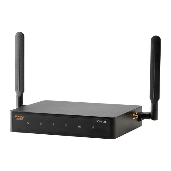
Chapter 1 9004-LTE Gateway The Aruba 9004-LTE gateway is a dual purpose gateway that supports both SD-WAN and wireless LAN capabilities. The gateway has the ability to directly connect a branch to cloud, provide resilient connectivity from the cloud, and centralized control for policy management across all branches. The wireless LAN connects, controls, and intelligently integrates wireless Access Points (APs), Managed Devices, and Air Monitors (AMs). -
Page 8: Aruba 9004-Lte Gateway Additional Accessories List
Aruba 90xx-LTE Spare SIM Tray Kit R6M37A Aruba 90xx-LTE Spare Outdoor Antenna Optional accessories available for use with the Aruba 9004-LTE gateway are sold separately. Contact your Aruba sales representative for details and assistance. Aruba 9004-LTE Gateway Components This section introduces the different component and its location in the Aruba 9004-LTE gateway. -
Page 9: Front Panel Leds
Connector Front Panel LEDs The front panel LEDs show the System, WAN, and LAN status including various other features. These front panel LEDs provide basic monitoring information of the overall status of the Aruba | Installation Guide 9004-LTE Gateway |... - Page 10 9004-LTE gateway. The following table describes the LED indicators and their corresponding status: Table 6 LED Status Function Indicator Status System System status Green (Solid) Powered and Operational Green (Blinking) Loading Software Amber (Solid) Critical Alarm Amber (Blinking) Major Alarm...
-
Page 11: Dc Power Connector
Red (Blinking) Hardware Failure. USB Failure. Unsupported USB Device Attached. DC Power Connector The AC-DC adapter kit with the following specification is used to power the Aruba 9004-LTE gateway: 12V/2.5A power interface Center-positive 2.1/5.5 mm circular plug, 9.5 mm length ... -
Page 12: Micro-Usb Console Port
USB connection takes precedence over the RJ-45 console connection. Micro-USB Driver To use the Micro-USB console port, you must install the Aruba Micro-USB driver on the computer that will manage your gateway. To download the driver, perform the following steps: 1. -
Page 13: Rj-45 Console Port
The Aruba 9004-LTE gateway also provides support for USB LTE Modems. If the Aruba 9004-LTE gateway has an active SIM card installed in the SIM card slot during boot up, then gateway does not initialize the external modem (even if the external modem is inserted before booting up the device). -
Page 14: Sim Tray
SIM Tray The 9004-LTE gateway is equipped with a dual nano-SIM tray. At any given time, only one SIM card is active and functional, the SIM 1 and SIM 2 can not be used simultaneously. To install a SIM card into the SIM tray, perform the following steps: 1. -
Page 15: Kensington Lock Slot
In case the SIM tray gets damaged or disfunctional, you can order a spare SIM tray available for use with the Aruba 9004-LTE gateway. The spare SIM tray is sold separately. Contact your Aruba sales representative for details and assistance. - Page 16 The GPS antenna is not included in the package. It is an additional accessory that can be ordered separately. Both, Aruba 90xx-LTE Spare Indoor Antenna and the Aruba 90xx-LTE Spare Outdoor Antenna can be used as GPS antennas along with the three extender kits available for 9004-LTE gateways. Refer page 8 for the types of extender kits.
-
Page 17: Installation
This chapter describes how to install the indoor LTE antennas on the Aruba 9004-LTE gateway. You can mount the Aruba 9004-LTE gateway on any flat surface such as a desktop, or a shelf. Or you can mount the gateway in a standard, 19-inch telco rack or on a wall using the various accessory kit (not included in box) provided by Aruba. -
Page 18: Antenna Mounting Instructions
(additional accessories, not provided in the package) for proper placement. To install a Main or Diversity antenna on an Aruba 9004-LTE gateway, perform the following steps: 1. Remove the protection caps from MAIN and DIV antenna connector. See... -
Page 19: Cable Saddle Installation Instructions
Your LTE antenna installation is now complete. Cable Saddle Installation Instructions The Aruba 9004-LTE gateway provides the option of attaching a cable saddle to the device to secure the power cable with the device. To attach a cable saddle to the 9004-LTE gateway, perform the following steps: 1. -
Page 20: Desktop Installation Instructions
Your cable saddle installation in now complete. Desktop Installation Instructions The Aruba 9004-LTE gateway can be kept on a desktop or any flat surface after the antenna and cable saddle installations are done. Just place the device on an open surface with the antennas pointing upright. - Page 21 (not included). See Figure Use 3/4 inch long #6 pan head wood screws for mounting 9004-LTE unit on wood. Use 3/4 inch long #6 pan head wood screws with plastic screw anchor #6-8 x 1 inch on dry wall ...
-
Page 22: Rack Mounting Installation Instructions
Suitable screwdrivers for all screw types provided in the box (not included in the kit) Some racks require screws that differ from those included with the 9004-LTE gateway kit. Ensure that you have the correct screws before installing the device. - Page 23 Hook one end of the clamp into the left hook provided on the tray, pull the other end and hook it to the right hook provided on the tray to secure the adapter completely. See Figure 21 Figure | Installation Guide Installation | Aruba 9004-LTE Gateway...
- Page 24 8. Align the wire saddles with the “L” shaped inscription on the rack. Remove the adhesive liner from the bottom of the wire saddles and attach each of the four wire saddles with the tray to secure them with the rack. See Figure 23 Figure | Installation | Installation Guide Aruba 9004-LTE Gateway...
- Page 25 Figure 24 Aligning the Wire Saddle 9. Insert the antenna wires into the wire saddles and attach it to the antenna connectors provided on the sides of the 9004-LTE gateway. This secures the wires within the wire saddle to keep it in place. See...
- Page 26 12.Remove the cable grommet from the outlet hole and insert the DC cable into the cable grommet through the slit provided. See Figure | Installation | Installation Guide Aruba 9004-LTE Gateway...
-
Page 27: Antenna Extension Instructions
14.Connect the DC cable into the DC jack on the device. 15.Insert the antenna wires into the wire saddles and attach it to the antenna connectors provided on the sides of the 9004-LTE gateway. This secures the wires within the wire saddle to keep it in place. - Page 28 The following tools and equipment are required for installing an LTE antenna: Mounting bracket for wall mount installation. Use 3/4 inch long #6 pan head wood screws for mounting 9004-LTE unit on wood (not included in the kit).
- Page 29 8. Align the antenna’s magnetic mounting base with the wall mounted bracket. The base of the LTE antenna is magnetic, and will attach with the wall mounted bracket automatically. Ensure that the base is placed in the circular space provided in the wall mount bracket. See Figure | Installation Guide Installation | Aruba 9004-LTE Gateway...
- Page 30 2. Mark the screw hole locations on a wall by aligning with the mounting holes provided in the mounting brackets for vertical orientation. 3. Align the mounting bracket to the screw hole on the wall. Secure the bracket with the screws on the wall. See Figure | Installation | Installation Guide Aruba 9004-LTE Gateway...
- Page 31 Figure 35 Mounting the LTE Antenna on the Bracket 6. Route the cable along the wall using required methods to ensure safety of the mounted antenna. Ensure that the antenna orientation is upright. See Figure | Installation Guide Installation | Aruba 9004-LTE Gateway...
-
Page 32: Outdoor Omni Antenna Extension Instructions: Aruba 90Xx-Lte Outdoor Ant Ext Kit-35Ft
The following tools and equipment are required for installing an Outdoor Omni antenna: Mounting bracket, nut, and washer (attached to the surge protector). Use 3/4 inch long #6 pan head wood screws for mounting 9004-LTE unit on wood (not included in the kit). - Page 33 7. Assemble the surge protector’s female end with the mounting bracket using the nut and washer. Figure 8. Assemble the Outdoor Omni antenna with the female end of the surge protector. See Figure | Installation Guide Installation | Aruba 9004-LTE Gateway...
- Page 34 3. Assemble the Outdoor Omni antenna with the female end of the surge protector. 4. Align the antenna with the pole and secure it using the pole mounting kit. See Figure | Installation | Installation Guide Aruba 9004-LTE Gateway...
- Page 35 6. Connect the 35 feet cable’s N-Type female connector with the N-Type male connector of the surge protector. See Figure Figure 40 Pole Mounted Outdoor Omni Antenna The Outdoor Omni antenna pole mounting is now complete. | Installation Guide Installation | Aruba 9004-LTE Gateway...
- Page 36 | Installation | Installation Guide Aruba 9004-LTE Gateway...
-
Page 37: Specifications, Safety, And Compliance
For additional specifications on this product, please refer to the data sheet. The data sheet can be found at www.arubanetworks.com Safety and Regulatory Compliance Aruba, a Hewlett Packard Enterprise company provides a multi-language document that contains country-specific restrictions and additional safety and regulatory information for all Aruba products. | Installation Guide Specifications, Safety, and Compliance |... -
Page 38: Fcc Class B Part 15
undesired operation. Changes or modifications to this unit not expressly approved by Aruba, a Hewlett Packard Enterprise company, can void the user’s authority to operate this equipment. This equipment has been tested and found to comply with the limits for a Class B digital device, pursuant to Part 15 of the FCC Rules. -
Page 39: Eu Regulatory Conformance
This product is a Class B product based on the standard of the VCCI Council. If this is used near a radio or television receiver in a domestic environment, it may cause radio interference. Install and use the equipment according to the instruction manual. | Installation Guide Specifications, Safety, and Compliance | Aruba 9004-LTE Gateway... -
Page 40: Thailand
Proper Disposal of Aruba Equipment Waste of Electrical and Electronic Equipment Aruba, a Hewlett Packard Enterprise company products at end of life are subject to separate collection and treatment in the EU Member States, Norway, and Switzerland and therefore are marked with the symbol shown at the left (crossed-out wheelie bin). -
Page 41: Korean
Korean Taiwan 1. 應避免影響附近雷達系統之操作。 2. 高增益指向性天線只得應用於固定式點對點系統 3. 電磁波暴露量 MPE 標準值 1 mW/cm2, 送測產品實測值為 : 0.223mW/cm2 所有技術文件皆必須秀出廠牌 / 型號,而使用手冊必須再補上警語,其警語內容如下:依據低功電波射性電機管辦法 第十二條 經型式認證合格之低功率射頻電機,非經許可,公司,商號或使用者均不得擅自變更頻率、加大功率或變更原設計之特 性及功能。 第十四條 低功率射頻電機之使用不得影響飛航安全及干擾合法通信;經發現有干擾現象時,應立即停用,並改善至無干擾時方得 繼續使用。 前項合法通信,指依電信法規定作業之無線電通信。 低功率射頻電機須忍受合法通信或工業、科學及醫療用電波輻射性 電機設備之干擾。 | Installation Guide Specifications, Safety, and Compliance | Aruba 9004-LTE Gateway... -
Page 42: Нормативные Требования Евразийского Экономического Союза
Brazil Este equipamento não tem direito à proteção contra interferência prejudicial e não pode causar interferência em sistemas devidamente autorizados. | Specifications, Safety, and Compliance | Installation Guide Aruba 9004-LTE Gateway...
Need help?
Do you have a question about the 9004-LTE and is the answer not in the manual?
Questions and answers