
Related Manuals for Pyle PLMRKT32


Summary of Contents for Pyle PLMRKT32
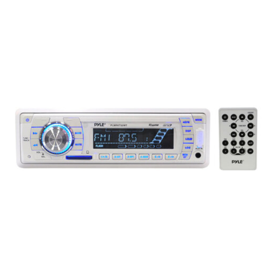
- Page 1 PLMRKT32 PLMR18 OWNER’S MANUAL Mobile Audio System • PLL Synthesizer Stereo Radio • Automatic Memory Storing • Preset Equalization • USB Interface • Auxiliary Input Function • Remote Control www.pyleaudio.com...
-
Page 2: Table Of Contents
CONTENTS Installation ...3 Take out screw before installation...3 DIN Front-Mount (Method A) ...3 Installing the unit ...3 Removing the unit...4 DIN Rear-Mount (Method B) ...5 Wiring Connection ...6 Operation ...7 Location of keys...7 Switching on/off the unit ...8 Sound adjustment...8 Loudness ...8 Display ...8 Mute...8... -
Page 3: Installation
INSTALLATION Notes: • Choose the mounting location where the unit will not interfere with the normal driving function of the driver. • Before finally installing the unit, connect the wiring temporarily and make sure it is all connected up properly and the unit and the system work properly. -
Page 4: Removing The Unit
INSTALLATION Sleeve L Key Outer Trim Ring Front Panel R Key 6. Mount the sleeve by inserting the sleeve into the opening of the dashboard and bend open the tabs located around the sleeve with a screwdriver. Not all tabs will be able to make contact, so examine which ones will be most effective. -
Page 5: Din Rear-Mount (Method B)
INSTALLATION DIN REAR-MOUNT (Method B) If your vehicle is a Nissan, Toyota, follow these mounting instructions. Use the screw holes marked T (Toyota), N (Nissan) located on both sides of the unit to fasten the unit to the factory radio mounting brackets supplied with your vehicle. -
Page 6: Wiring Connection
WIRING CONNECTION ANTENNA CONNECTOR FUSE IGNITION SWITCH (ACC+) FUSE MEMORY YELLOW BACK-UP (B+) BLACK GROUND (B–) POWER BLUE ANTENNA FRONT Lch SPEAKER WHITE/BLACK GREEN REAR Lch SPEAKER GREEN/BLACK MAIN UNIT WHITE (GREY) Rch RED RCA CABLE Lch WHITE GREY FRONT Rch SPEAKER GREY/BLACK VIOLET... -
Page 7: Operation
OPERATION LOCATION OF KEYS... -
Page 8: Switching On/Off The Unit
OPERATION • SWITHCHING ON/OFF THE UNIT Switch on the unit by pressing any button. When system is on, press button (1) to turn off the unit. • SOUND ADJUSTMENT Press SEL button (3) shortly to select the desired adjustment mode. The adjustment mode will change in the following order: (Volume) -
Page 9: Station Storing
OPERATION • STATION STORING Press any one of the preset button(18) (1 to 6) to select a station, which had been stored in the memory. Press this button for several seconds (until 2ND beeps come out), current station is stored into the number button. •... - Page 10 OPERATION • SELECTING TRACKS BY AS/PS/Navi-SCH BUTTON AS/PS (Navi-SCH) button is assigned as file searching button in MP3 file operation. When pressed, it is activated as selecting each mode of Digital Audio. “Searching track number” => “Navigation”from root by volume knob =>...
-
Page 11: Sd/Mmc Operation
OPERATION SUPPORTED MP3/WMA DECODING MODES The main unit supports MP3/WMA (Windows Media Audio) decoding modes as below. Standard Bit Rate (kbps) MPEG1 Audio 32, 48, 64, 96, Layer 3 128, 192, 256, (44.1kHz) Windows 64, 96, 128, Media Audio (44.1kHz) The USB solution can support: 1. -
Page 12: Specification
SPECIFICATION GENERAL Power Supply Requirements Chassis Dimensions Tone Controls - Bass (at 100 Hz) - Treble (at 10 KHz) Maximum Output Power Current Drain CD PLAYER Signal to Noise Ratio Channel Separation Frequency Response RADIO Frequency Coverage Sensitivity (S/N = 30 dB) Stereo Separation Frequency Coverage Sensitivity (S/N = 20 dB) -
Page 13: Trouble Shooting
TROUBLE SHOOTING Before going through the checklist, check wiring connection. If any of the problems persist after checklist has been made, consult your nearest service dealer. Symptom No power. The car ignition switch is not on. The fuse is blown. No sound. - Page 14 8800-0C3023-02...
Need help?
Do you have a question about the PLMRKT32 and is the answer not in the manual?
Questions and answers