Table of Contents
Advertisement
ISTRUZIONI PER L'INSTALLAZIONE E LA MANUTENZIONE
INSTRUCTIONS POUR L'INSTALLATION ET LA MAINTENANCE
INSTRUCTIONS FOR INSTALLATION AND MAINTENANCE
INSTALLATIONS- UND WARTUNGSANLEITUNGEN
INSTRUCTIES VOOR INSTALLATIE EN ONDERHOUD
INSTRUCCIONES DE INSTALACIÓN Y MANTENIMIENTO
INSTALLATIONS- OCH UNDERHÅLLSANVISNING
РУКОВОДСТВО ПО МОНТАЖУ И ТЕХНИЧЕСКОМУ ОБСЛУЖИВАНИЮ
KURMA VE BAKIM BİLGİLERİ
ΟΔΗΓΙΕΣ ΓΙΑ ΤΗΝ ΕΓΚΑΤΑΣΤΑΣΗ ΚΑΙ ΤΗ ΣΥΝΤΗΡΗΣΗ
INSTRUCTIUNI PENTRU INSTALARE SI INTRETINERE
NAVODILA ZA VGRADNJO IN UPORABO
ИНСТРУКЦИЯ ЗА МОНТАЖ И ПОДДРЪЖКА
INSTALLÁCIÓS ÉS KARBANTARTÁSI UTASÍTÁS
MCE-150/C
MCE-110/C
V7.0
Advertisement
Table of Contents

Related Manuals for DAB MCE-150/C


Summary of Contents for DAB MCE-150/C
- Page 1 INSTALLATIONS- OCH UNDERHÅLLSANVISNING РУКОВОДСТВО ПО МОНТАЖУ И ТЕХНИЧЕСКОМУ ОБСЛУЖИВАНИЮ KURMA VE BAKIM BİLGİLERİ ΟΔΗΓΙΕΣ ΓΙΑ ΤΗΝ ΕΓΚΑΤΑΣΤΑΣΗ ΚΑΙ ΤΗ ΣΥΝΤΗΡΗΣΗ INSTRUCTIUNI PENTRU INSTALARE SI INTRETINERE NAVODILA ZA VGRADNJO IN UPORABO ИНСТРУКЦИЯ ЗА МОНТАЖ И ПОДДРЪЖКА INSTALLÁCIÓS ÉS KARBANTARTÁSI UTASÍTÁS MCE-150/C MCE-110/C V7.0...
- Page 2 ITALIANO pag. FRANÇAIS page ENGLISH page DEUTSCH seite NEDERLANDS pag. ESPAÑOL pág. SVENSKA sid. РУССКИЙ стр. TÜRKÇE ΕΛΛΗΝΙΚΑ σελ. ROMANA pag. SLOVENŠČINA stran. БЪЛГАРСКИ Стр. MAGYAR Old.
-
Page 3: Table Of Contents
ENGLISH INDEX KEY.......................................33 GENERAL ....................................33 Safety ....................................34 Responsibility ..................................34 Particular warnings ................................34 APPLICATIONS ...................................34 TECHNICAL DATA ..................................34 Electromagnetic Compatibility (EMC) ..........................35 ELECTRICAL CONNECTIONS..............................35 Connection to the Power Supply Line ..........................35 Connection to the Electropump ............................35 Earth Connection ................................36 Connection of the Differential Pressure Sensor ......................36 Electrical Connections of Inputs and Outputs ........................37 5.5.1 Digital Inputs ................................37... -
Page 4: Safety
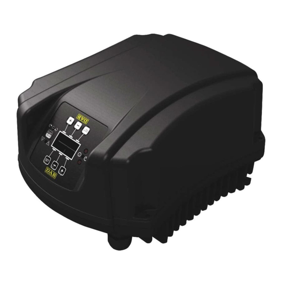
(head); it is thus possible to adapt the performance of the circulation pump to the actual demands of the system. This determines considerable energy saving, a greater possibility of control of the system, and reduced noise. The MCE-150/C inverter is designed so that it can be housed directly on the pump motor body. TECHNICAL DATA... -
Page 5: Electromagnetic Compatibility (Emc)
Although the MCE-150/C has its own internal protections, it is still advisable to install a suitably sized thermal magnetic circuit breaker. ATTENTION: The thermal magnetic circuit breaker and the power cables of the MCE-150/C and of the pump must be of a size suited to the system;... -
Page 6: Earth Connection
Table 2: Cable section Connection of the Differential Pressure Sensor The MCE-150/C accepts two types of differential pressure sensor: ratiometric with full scale value 4 bar or ratiometric with full scale value 10 bar. The cable must be connected at one end to the sensor and at the other to the pressure sensor input provided on the inverter, marked "Press 1"... -
Page 7: Electrical Connections Of Inputs And Outputs
Electrical Connections of Inputs and Outputs The MCE-150/C has 3 digital inputs, 2 NTC inputs for fluid temperature measurement T and T1 an analogue input and 2 digital outputs so as to be able to make certain interfaces with more complex installations. - Page 8 ENGLISH Figure 4: Example of Connection of Digital Inputs Start/Stop and Economy Functions associated with the digital inputs Start/Stop: If input 1 is activated from the control panel (see par. 9) it will be possible to command the switching on and off of the pump in remote mode. Economy: If input 2 is activated from the control panel (see par.
-
Page 9: Analogue Input 0-10V
ENGLISH 5.5.2 Analogue input 0-10V The analogue input 0-10V is screen-printed at the base of the 18-pole terminal board: A1V (terminal 9): Positive pole GND (terminal 10): Negative pole A2V (terminal 4): Positive pole GND (terminal 5): Negative pole The function associated with the analogue input A1V is that of regulating the pump rotation speed in proportion to the input voltage 0-10V itself (see par. -
Page 10: Outputs
ENGLISH Figure 8: Connection of NTC sensor for temperature measurement T N.B. Temperature reading via sensor T is only enabled in the following control modes: T constant increasing /decreasing and ∆T constant N.B. Temperature reading via sensor T1 is only enabled in the following control modes: T1 constant increasing /decreasing and ∆T constant For operating modes T constant and ∆T constant see paragraphs 7.1.5 and 7.1.6... -
Page 11: Connection For Twin Systems
Connection for Twin Systems To make a twin system it is sufficient to connect the 2 inverters MCE-150/C using the cable supplied, fitting it onto both inverters in one of the 2 connectors indicated by the word Link (see Figure 3). -
Page 12: Regulation With Constant Differential Pressure
7.1.1 Regulation with Constant Differential Pressure The head remains constant, irrespective of the water request. This mode may be set by means of the control panel on the cover of the MCE-150/C (see par. 9). 7.1.2 Regulation with Constant Curve The rotation speed is kept at a constant number of revolutions. -
Page 13: Quick Start Function
CONTROL PANEL The functions of the MCE-150/C may be modified by means of the control panel on the cover of the MCE-150/C itself. On the panel there are: a graphic display, 7 navigation buttons and 3 LED warning lights (see Figure 10). -
Page 14: Graphic Display
ENGLISH Figure 10: Control Panel Graphic Display Using the graphic display it will be possible to navigate in an easy and intuitive menu which will enable you to check and modify the system operating mode, the enabling of the inputs and the working set-point. It will also be possible to view the system status and the log of any alarms memorised by the system. - Page 15 ENGLISH Table 5 describes the parameters sensitive to the inverter and provided in the advanced menu. To exit the advanced menu, scroll through all parameters using the central button. Parameter Measurement Description Range symbol unit Serial Unique serial number attributed for connectivity Electric pump rated frequency Set the value stated on 50 - 200 the electric pump dataplate.
- Page 16 ENGLISH Page 2.0 The regulating mode is set from Page 2.0. It is possible to choose from 9 different modes: = Regulation with constant differential pressure = Regulation with constant curve with speed set from the display. = Regulation with constant curve with speed set by remote signal 0-10V. = Proportional differential pressure regulation.
- Page 17 ENGLISH Page 7.0 If a twin system is used (see Par. 0), on page 7.0 you can set one of the 4 possible twin operating modes: Alternate every 24h: The 2 inverters alternate in regulation every 24 operating hours. If one of the 2 malfunctions, the other takes over regulation. Simultaneous: The 2 inverters work at the same time and at the same speed.
-
Page 18: 10. Factory Settings
ENGLISH 10. FACTORY SETTINGS Parameter Value Regulating mode = Regulation with constant differential pressure Hs (Differential Pressure Set-point) 50% of the max. pump head (see inverter sensitive parameters set in factory) Fs (Frequency Set-point) 90% of the pump rated frequency Tmax 50 ºC Operating mode...
Need help?
Do you have a question about the MCE-150/C and is the answer not in the manual?
Questions and answers