Table of Contents
Advertisement
Quick Links
Before commencing assembly,please read these instructions thoroughly.
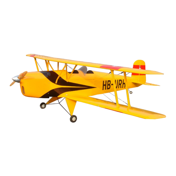
Bucker Jungmann
SAFETY PRECAUTIONS
This radio control model is not a toy!
lFirst-time builders should seek advice from people having building
experience in order to assemble the model correctly and to produce
its performance to full extent.
lAssemble this kit only in places out of childrens reach!
lTake enough safety precautions prior to operating this model.
You are responsible for this model s assembly and safe operation!
lAlways keep this instruction manual ready at hand for quick
reference,even after completing the assembly.
lCould cause serious injury or even death
All manuals and user guides at all-guides.com
ALMOST - READY - TO - FLY
ALMOST - READY - TO - FLY
,
,
SPECIFICATION
Wing Span:2500 mm (98.4 in)
2
Wing Area:113.2 dm (1755 sq.in)
Fuselage Length: 2230 mm (87.8 in)
Engine : 50cc gas engine
Radio : 4 channels ,9 servos
Advertisement
Table of Contents

Related Manuals for CYmodel Bucker Jungmann CY8120B


Summary of Contents for CYmodel Bucker Jungmann CY8120B
- Page 1 All manuals and user guides at all-guides.com Before commencing assembly,please read these instructions thoroughly. ALMOST - READY - TO - FLY ALMOST - READY - TO - FLY Bucker Jungmann SAFETY PRECAUTIONS SPECIFICATION This radio control model is not a toy! Wing Span:2500 mm (98.4 in) lFirst-time builders should seek advice from people having building Wing Area:113.2 dm (1755 sq.in)
-
Page 2: Before You Begin
All manuals and user guides at all-guides.com REQUIRED FOR OPERATION (Purchase separately) REQUIRED FOR OPERATION (Purchase separately) REQUIRED FOR OPERATION (Purchase separately) REQUIRED FOR OPERATION (Purchase separately) A minimum 4channel radio for airplanes (with 9servos). B B B B Glue And dry batteries. - Page 3 All manuals and user guides at all-guides.com Accessory list for this page. Install the aileron servo Below wing HORN 3X25mm screw Bottom view - - - - - 4 - - - - - 12 - - - - - 4 2X8mm screw - - - - - 8...
-
Page 4: Install The Elevator
All manuals and user guides at all-guides.com Install the elevator Accessory list for this page. 4x16mm screw - - - - - 2 3x12mm screw - - - - - 4 4mm Washer - - - - - 6 12X355mm tube 12X355mm tube 8mm nylon Nut 3x12mm... -
Page 5: Install The Top Wing
All manuals and user guides at all-guides.com Examine the top wing Accessory list for this page. 8X35mm screw HORN - - - - - 2 - - - - - 2 - - - - - 8 1250mm Steel wire - - - - - 2 - - - - - 2 4X25mm screw... -
Page 6: Install The Tail Wheel
All manuals and user guides at all-guides.com Accessory list for this page. Install the main landing gear 5.2mm Collar 3X3mm screw Connecting rod head 3X25mm Tp screw - - - - - - 2 - - - - - - 2 - - - - - 2 - - - - - 2 - - - - - -12... -
Page 7: Radio Equipment
All manuals and user guides at all-guides.com Accessory list for this page. Install the engine(50cc gas engine) Linkage Stopper 1.8X400mm Rod - - - - - - 1 - - - - 1 - - - - 1 165mm fuel tank fuel tank 3X3mm Screw - - - - 1... - Page 8 All manuals and user guides at all-guides.com Accessory list for this page. Install the wing steel wire 2X8mm screw joint Rod adjuster 950mm Steel wire 3X12mm Tp screw - - - - - 8 - - - - - 8 - - - - - 2 - - - - - 2 - - - - - 4...
- Page 9 All manuals and user guides at all-guides.com Adjustment. Adjustment Adjust the travel of each control surface to the Adjust the travel of each control surface to the values in the diagrams. values in the diagrams. These values fit general flight capabilities. These values fit general flight capabilities.
Need help?
Do you have a question about the Bucker Jungmann CY8120B and is the answer not in the manual?
Questions and answers