ADC HiGain HLU-200 User Manual
List 1a line unit
Hide thumbs
Also See for HiGain HLU-200:
- User manual (65 pages) ,
- Quick installation manual (7 pages) ,
- User manual (26 pages)

Related Manuals for ADC HiGain HLU-200


Summary of Contents for ADC HiGain HLU-200
- Page 1 HiGain HiGain ANUAL HLU200 L1A LOOP FAIL HDSL HLU-200 List 1A Line Unit ProductCatalog: 350-200-111-02 (db) CLEI: SLL2U6LG SETUP AHT1U...
- Page 2 In no event shall ADC be liable for any damages resulting from loss of data, loss of use, or loss of profits, and ADC further disclaims any and all liability for indirect, incidental, special, consequential or other similar damages.
- Page 3 Unpack each container and inspect the contents for signs of damage. If the equipment has been damaged in transit, immediately report the extent of damage to the transportation company and to ADC DSL Systems, Inc. Order replacement equipment, if necessary.
-
Page 4: Table Of Contents
Table of Contents 350-200-111-02, Issue 2 ABLE OF ONTENTS Overview ________________________________________________1 Compatibility................2 Front Panel ................3 Installation ______________________________________________5 Setting the HDSL Line Voltage Option ........5 Installing the HLU-200 ............6 Provisioning _____________________________________________7 Using the Mode and Select Buttons .........7 Default Settings ................8 Using the Craft Port..............8 System Settings ................9 Troubleshooting _________________________________________12... -
Page 5: Overview
350-200-111-02, Issue 2 Overview VERVIEW ® ® The ADC HiGain Line Unit Model HLU-200 List 1A (AHT1U) is an asynchronous DS1 interface unit that plugs into the Channel Bank Assembly ® (CBA) of a DSC Litespan 2000 optical loop carrier system to provide a High-bit-rate Digital Subscriber Line (HDSL) interface. -
Page 6: Compatibility
Overview 350-200-111-02, Issue 2 OMPATIBILITY The HLU-200 List 1A operates as a channel card in a DSC Litespan-2000 Channel Bank. The Litespan-2000 system consists of a Central Office (CO) bank connected to a remote bank over an Optical Carrier 3 (OC3) fiber link. Each bank has slots for 56-channel plug-ins. -
Page 7: Front Panel
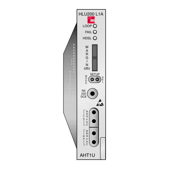
350-200-111-02, Issue 2 Overview RONT ANEL HLU200 L1A LOOP FAIL Status LEDs HDSL Four-character display (db) SETUP RS-232 craft Mode and Select buttons port Test ports Pull tab AHT1U Figure 1. HLU-200 List 1A Front Panel HLU-200 List 1A October 4, 1999... - Page 8 Overview 350-200-111-02, Issue 2 Table 1. Front Panel Features Name Function Status LEDs Indicates system status. Loop LED Lights whenever any of the HLU-200 system loopbacks are in effect. Flashes when the AHT1U is in the armed state for an intelligent repeater loopback command.
-
Page 9: Installation
Installation NSTALLATION Upon receipt of the equipment, visually inspect it for signs of damage. If the equipment has been damaged in transit, immediately report the extent of damage to the transportation company and to ADC. HDSL L ETTING THE OLTAGE PTION The HDSL line powering voltage is set by the S1 switch. -
Page 10: Installing The Hlu-200
Installation 350-200-111-02, Issue 2 HLU-200 NSTALLING THE To install the HLU-200 into a Litespan-2000 channel bank: Slide the HLU-200 into the card guides for the desired slot, then push the unit in until it touches the channel-bank backplane card-edge connector. Carefully push the unit in until it is entirely within the card guide, making sure that the unit is properly seated. -
Page 11: Provisioning
350-200-111-02, Issue 2 Provisioning ROVISIONING All HLU-200 List 1A user options can be set using either the front panel Mode and Select buttons (in conjunction with the four-character display) or from the Maintenance Terminal menus through a maintenance terminal connected to the front-panel RS-232 maintenance port. Only the DS1 line code (B8ZS or AMI) is sent to the Litespan system manager, which reads the value and then provisions the Litespan Gate Array. -
Page 12: Default Settings
Provisioning 350-200-111-02, Issue 2 EFAULT ETTINGS To return the system options to the original factory default settings: Press the SEL button until the DFLT NO message appears. Press the SEL button again and DFLT YES displays indicating the factory default values are now in effect. To terminate the DFLT mode without setting the factory default values, press the MODE button or do nothing for 30 seconds. -
Page 13: System Settings
350-200-111-02, Issue 2 Provisioning On each screen, enter the key represented by the letter in parentheses for the parameter to be changed. • Each entry of the letter scrolls the parameter to its next value. • After all selections have been made, press to exit and confirm the changes. - Page 14 Provisioning 350-200-111-02, Issue 2 Table 2. System Settings (Cont.) Mode Selection Description LPBK Configures the HLU-200 to ignore the 2-in-5 Smart-Jack loopback command. Enables the HLU-200 to respond to the 2-in-5 Smart-Jack loopback command. SPLB GNLB Configures the HiGain system to respond to the generic (3-/4-/5-/6-in-7) in-band loopback codes.
- Page 15 350-200-111-02, Issue 2 Provisioning Table 2. System Settings (Cont.) Mode Selection Description HAIS Causes HiGain to transmit the AIS signal at both the HLU and HRU T1 output ports when both of the HDSL loops are not in sync (LOSW). Causes HiGain to transmit the AIS signal at both the HLU and HRU T1 output ports when either of the two HDSL loops is not in sync (LOSW) or if a minor alarm occurs.
-
Page 16: Troubleshooting
Troubleshooting 350-200-111-02, Issue 2 ROUBLESHOOTING Minor alarm and diagnostic messages routinely appear on the HLU-200 front-panel four-character display. This display automatically turns on when power is initially applied to the HLU-200. To conserve power, the display remains on for only 5 minutes if neither the MODE or SEL buttons are pressed. -
Page 17: Loopbacks
350-200-111-02, Issue 2 Troubleshooting OOPBACKS The HLU-200 loopback messages are listed in the following table. The GNLB locations and their activation codes are also shown in Figure 3 on page Table 4. Loopback Messages Message Full Name Description CREM Customer Remote Signal from customer is looped back to customer Loopback at the HLU. - Page 18 Troubleshooting 350-200-111-02, Issue 2 The following generic loopback mode diagram (Figure 3), shows the GNLB locations and their activation codes. Figure 3. Generic Loopback Mode October 4, 1999 HLU-200 List 1A...
-
Page 19: Four-Character Diagnostic Messages
350-200-111-02, Issue 2 Troubleshooting HARACTER IAGNOSTIC ESSAGES The HLU-200 diagnositc messages are listed in the table below. Table 5. Four-Character Diagnostic Messages Message Full Name Description 1=xx or 2=yy HDSL Loop Margins Indicates the power of the received HDSL signal on each loop relative to noise. - Page 20 Troubleshooting 350-200-111-02, Issue 2 Table 5. Four-Character Diagnostic Messages (Cont.) Message Full Name Description Super Frame Indicates the T1 input to the AHT1U in a superframe format, if the FRMC option is set to AUTO. Extended Super Frame Indicates the T1 input to the AHT1U in an extended superframe format, if the FRMC option is set to AUTO.
-
Page 21: Specifications
350-200-111-02, Issue 2 Specifications PECIFICATIONS Maximum Power Consumption Without doubler 13 W With doubler 20 W Maximum Heat Dissipation Without doubler With doubler 6.3 W Mounting Litespan-2000 CBA/ONU-48, 96 Dimensions Height 4.42 inches (11.22 cm) Width 0.84 inches (2.13 cm) Depth 10.2 inches (25.9 cm) Weight... - Page 22 Specifications 350-200-111-02, Issue 2 Figure 4. Card-edge Connector October 4, 1999 HLU-200 List 1A...
-
Page 23: Power Parameters
350-200-111-02, Issue 2 Power Parameters OWER ARAMETERS AHT1U A OUBLER PPLICATIONS This section discusses HLU-200 List 1A operations when used without doublers. Nondoubler HLU-200 current drains on the two CBA power supplies, power consumption and dissipation are listed in Table Table 6. -
Page 24: Doubler Ahtiu Applications
Power Parameters 350-200-111-02, Issue 2 AHTIU A OUBLER PPLICATIONS One or two doublers may be used in the HDSL loops between the HLU-200 and the HRU. When using two doublers in an HDSL loop, the HRU must be locally powered. This section discusses HLU-200 operation with the following doublers: HDU-451 List 3 and List 4;... - Page 25 350-200-111-02, Issue 2 Power Parameters Table 7. HLU-200 List 1A Power Parameters for Doubler Applications (HDU-451 List 3 and 4; HDU-437, and HDU-439) Line-powered HRU Locally-powered HRU One Doubler Power Bus CPE-I CPE-I ON One Doubler Two Doublers +5 Vdc 600 mA 600 mA 600 mA...
- Page 26 Power Parameters 350-200-111-02, Issue 2 Table 9. HLU-200 List 1A Power Worksheet HRU Power Worksheet Factors Doubler No. of Model CPE-I HDUs Line Local None None 0.133 None None None Off/On None HDU-451 0.351 List 3 & 4; HDU-439; HDU-437 HDU-451 Off/On 0.133...
-
Page 27: Product Support
UPPORT ADC Customer Service Group provides expert pre-sales and post-sales support and training for all its products. Technical support is available 24 hours a day, 7 days a week by contacting the ADC Technical Assistance Center (TAC). • Quotation Proposals Sales Assistance •... - Page 28 Product Support 350-200-111-02, Issue 2 October 4, 1999 HLU-200 List 1A...
-
Page 29: Certification And Warranty
12-month warranty period per ADC's instructions and which product is confirmed by ADC not to comply with the foregoing warranty. ADC warrants that, for a period of 90 days from the date of purchase, the software furnished with its products will operate substantially in accordance with the ADC published specifications and documentation for such software. - Page 30 ADC DSL Systems, Inc. 14402 Franklin Avenue Tustin, CA 92780-7013 Tel: 714.832.9922 Fax: 714.832.9924 Technical Assistance Tel: 800.638.0031 Tel: 952.917.3222 Fax: 714.730.2400 ISO 9001/TL 9000 DNV Certification, Inc. REGISTERED FIRM : 350-200-111-02, SSUE OCUMENT ´,2~¶8<¨ 1218948...
Need help?
Do you have a question about the HiGain HLU-200 and is the answer not in the manual?
Questions and answers