
Related Manuals for HP E34m G4


Summary of Contents for HP E34m G4
- Page 1 Maintenance and Service Guide E34m G4 model SUMMARY This guide provides information about spare parts, removal and replacement of parts, diagnostic tests, problem troubleshooting, and more.
- Page 2 Devices, Inc. Bluetooth is a trademark sure to read “Important Safety Information”. owned by its proprietor and used by HP Inc. under license. NVIDIA is a trademark and/or registered trademark of NVIDIA Corporation in the U.S. and other countries.
-
Page 3: Table Of Contents
Table of Contents 1 Getting started .............................. 1 Important safety information ........................1 Important service information and precautions ..................1 RoHS (2002/95/EC) requirements ......................2 General descriptions ..........................2 Firmware updates ............................ 2 Before returning the repaired product to the customer ................2 2 Monitor features ............................ -
Page 4: Getting Started
Getting started Read this chapter to learn about safety information and where to find additional HP resources. Important safety information Carefully read the cautions and notes within this document to minimize the risk of personal injury to service personnel. The cautions and notes are not exhaustive. Proper service methods are important to the safe, reliable operation of equipment. -
Page 5: Rohs (2002/95/Ec) Requirements
Level 2: Circuit board or standard parts replacement Firmware updates Firmware updates for the monitor are available at support.hp.com. If no firmware is posted, the monitor does not need a firmware update. Before returning the repaired product to the customer Perform an AC leakage current check on exposed metallic parts to be sure the product is safe to operate without the potential of electrical shock. -
Page 6: Monitor Features
● Removable stand for flexible monitor head mounting solutions ● HP Quick Release 2 device to quickly attach the monitor head to the stand with a simple click, and then remove it with the convenient sliding tab release. 3 ... - Page 7 For safety and regulatory information, refer to the Product Notices provided in your documentation kit. To access the latest user guides or manuals for your product, go to http://www.hp.com/support and follow the instructions to find your product. Then select Manuals. ...
-
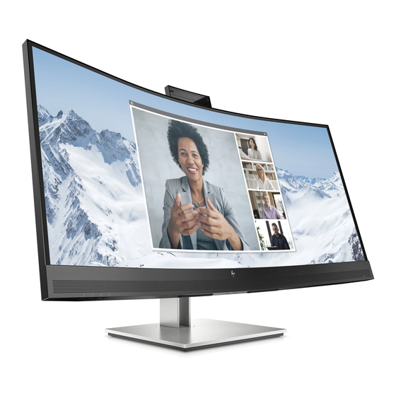
Page 8: Front Components
Front components To identify the components on the front of the monitor, use this illustration and table. Table 1-2: Front components and their descriptions Component Function Camera Allows you to video chat, record video, and record still images NOTE: Camera functions vary depending on the camera hardware and software installed on your product. -
Page 9: Rear Components
Regulatory, Safety, and Environmental Notices To access this guide, type HP Documentation in the taskbar search box, and then select HP Documentation. NOTE: When a device is connected to the jack, the speakers are disabled. Power button Turns the monitor on or off. - Page 10 DisplayPort Connects a DisplayPort cable from the source device to the monitor. USB Type C Connects a USB TypeC cable from the source device to the monitor. Serves as a single (10) Network jack Connects an RJ45 Ethernet cable to the monitor. Connects a USB device, provides highspeed (11) USB ports (2)
-
Page 11: Locating The Serial Number And Product Number
The SPEC label (1) and Barcode label (2) are located on the rear of the monitor. The serial number and product number are located on a Safety label. You may need these numbers when contacting HP about the monitor model. - Page 12 For India: Bar code label Spec label 9 ...
-
Page 13: Illustrated Parts Catalog
Illustrated parts catalog To identify the monitor major components, use this illustration and table. Item Description LOGO HP 12 DECO_BEZEL L34WRC-Dhp4-p4 BASE_ASS’Y NA N/A stand ass'y NA NA SHIELD_AUDIO SHIELD_USB LCD TPM340Y1-2H012 21B FQ TPV MIDDLE_FRAME L34WRC-Dhp4-p4 ADAPTER BOARD NA... -
Page 14: How To Order Parts
0M1G3030 5120 QM1G38400601200ARA QQ1G353000412000RA 0Q1G2030 6120 0M1G102500404700RA Q01G6019 1 How to order parts The HP authorized repair center can purchase the power board from HP. Power board Description HP spare part number Manufacturer part number PSU E34m G4 N02581-001 PLPCLL482UAA1 Capacitors and connectors are available for purchase from the following EU distributors: ... - Page 15 Internal and External Power Supplies are available for purchase from the following EU distributor: EET https://www.eetgroup.com/en-eu/ NOTE: HP continually improves and changes product parts. For complete and current information about supported parts for your product, go to https://partsurfer.hp.com/Search.aspx, select your country or region, and then follow the on-screen instructions.
-
Page 16: Removal And Replacement Procedures
Removal and replacement procedures Adherence to these procedures and precautions is essential for proper service. Preparation for disassembly Use this information to properly prepare to disassemble and reassemble the monitor. 1) Read the “Important safety information” and “Important service information and precautions” sections in the “Getting started”... - Page 17 2) Use your fingers to split the left and right sides apart between the middle frame and rear case. 3) Insert the scraper bar tool into the gap between the middle frame and rear case, and then rotate. The hook opens. Repeat the steps. 4) Disassemble Rear Cover.
- Page 18 6) Remove the Audio board wire, Connector board wire and Webcam module wire from the Interface- board. 7) Disassemble the USB board from the Rear Cover (if required). 8) Remove 2 screws from the bracket. 15 ...
-
Page 19: Power Board
Before removing the power board, follow these steps: ▲ Prepare the monitor for disassembly. See Preparation for disassembly on page 13. Remove the power board: 1) The HP E34m G4 power board connector position is as follows: Warning: After unplugging the power supply, the capacitance is still charged, do not touch and discharge the capacitor. -
Page 20: Connector Repair
Connector repair This procedure includes HDMI, DisplayPort, USB Type-C, RJ-45 and USB 3.0 connectors. The connectors are on the main board (board part number CBPR1R4H0Q3). The connectors identifiers are as follows: Connector Location HDMI1 CN501 CN502 USB Type-C CN503 RJ45 CN103... - Page 21 This procedure includes USB 3.0 A connectors. The connectors are on the Connector board (board part number CTPCPQE4). The connectors identifiers are as follows: Connector Location USB 3.0 A CN154 USB 3.0 A CN153 Audio Board CN153 CN154 Before repairing connectors, follow these steps: ▲...
-
Page 22: Hdmi 1 Connector Cn501
HDMI 1 connector CN501 Repair the HDMI connector: 1) Use a soldering iron and a de-soldering pump to remove as much solder as possible from the pin. 2) Use a hot air gun to melt the solder on the pins. 3) Lift the CN501 connector from the circuit board. -
Page 23: Usb Type-C Connector Cn503
3) Lift the CN502 connector from the circuit board. 4) Place the new component on the circuit board. Be sure that it matches the footprint. 5) Solder the new component. USB Type-C connector CN503 Repair the USB Type-C connector: 1) Use a soldering iron and a de-soldering pump to remove as much solder as possible from the pin. 2) Use a hot air gun to melt the solder on the pins. -
Page 24: Rj45 Connector Cn103
RJ45 connector CN103 Repair the RJ-45 connector: 1) Use a soldering iron and a de-soldering pump to remove as much solder as possible from the pin. 2) Lift the CN103 connector from the circuit board. 3) Place the new component on the circuit board. Be sure that it matches the footprint. 4) Solder the new component. -
Page 25: Audio Connector Cn610
AUDIO connector CN610 Repair the Audio connector: 1) Use a hot air gun to melt the solder on the pins. Pin solder with soldering iron and absorber. You can gently push down with the soldering iron once everything is molten to move the M1 out of the through holes. -
Page 26: Function Test
2) Lift the CN154、CN153 connector from the circuit board. 3) Place the new component on the circuit board. Be sure that it matches the footprint. 4) Solder the new component. Function test After repair, be sure to confirm that all functions are working. Table 4-1: Function test Test item... - Page 27 Video card is incompatible. Open the OSD menu and select the Input menu. Set Auto-Switch Input to Off and manually select the input or replace the video card or connect the video cable to one of the computer’s on-board video sources.
-
Page 28: Index
Index components preparation for disassembly, 13 front, 5 RC removal, 13 rear, 6 rear components, 6 connector repair, 17 removal features, 3 power board, 16 firmware updates, 2 RC, 13 front components, 5 removal and replacement procedures, 13 function test, 23 returning to customer, 2 how to order parts, 11...
Need help?
Do you have a question about the E34m G4 and is the answer not in the manual?
Questions and answers