Table of Contents
Advertisement
Quick Links
Advertisement
Table of Contents

Related Manuals for Datacolor 110


Summary of Contents for Datacolor 110
- Page 1 Datacolor Datacolor 110™ User’s Guide...
- Page 2 Datacolor 110 User’s Guide (July, 2005) Part No. 4230-0394M Rev 1 All efforts have been made to ensure the accuracy of the information presented in this format. However, should any errors be detected, Datacolor appreciates your efforts to notify us of these oversights.
-
Page 3: Table Of Contents
Communications Cable ..................6 USB Driver Installation ....................7 Installing the Driver....................7 Viewing/Changing System Port Assignment ............11 Changing the COM Port Assignment in Datacolor Programs ......15 Instrument Calibration Data ................. 15 Controls and Indicators ..................17 Status Panel ....................... 17 Powering Up ....................... -
Page 5: Datacolor 110
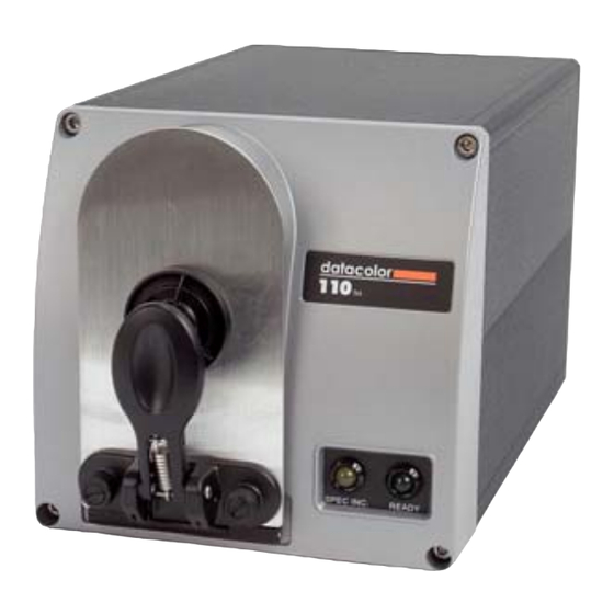
Datacolor 110™ About the Datacolor 110™ The Datacolor 110™ is a member of the newest generation of Datacolor bench top color measuring instruments, incorporating state-of-the-art CMOS integrated circuit technology in the instrument design. It is intended for use as a device for measuring, specifying and evaluating color in both laboratory and retail settings. -
Page 6: Light Source
CAUTION Disconnect power before servicing. The power cord supplied with the unit must be used. Feature Summary The Datacolor 110™ employs state-of-the-art features including the spectrometer, integrating sphere, light source, and optics. Below is a summary of those features: FEATURE... -
Page 7: Calibration Tiles
The green tile is used to perform an optional diagnostic test. Aperture Plates The Datacolor 110 is a single aperture instrument. However, a variety of aperture sizes are available to accommodate different applications. Consult with a Datacolor representative to determine the correct aperture size for your application. - Page 8 N O T E S 4 • Accessories Datacolor 110 User's Guide...
-
Page 9: Cable Installation
BE SURE TO TURN OFF THE POWER BEFORE WORKING WITH ANY CABLES. The Datacolor 110™ requires the use of two cables, a power cable and either a serial cable or a USB cable, to connect the instrument to the computer. -
Page 10: Power Cable
RS-232C connector pin assignments. If you are using a USB port, there is additional software that must be installed. See USB Driver Installation in this guide for detailed instructions regarding the software installation. 6 • Cables Datacolor 110 User's Guide... -
Page 11: Usb Driver Installation
The New Hardware Wizard automatically replaces this screen. Click Next to continue with the USB driver installation. USB Driver Installation • 7 Datacolor 110 User's Guide... - Page 12 To add a check, place the cursor in a blank box and click the mouse. A check will appear. − To remove a check, place the cursor over a check, and click the mouse. The check will disappear. 8 • USB Driver Installation Datacolor 110 User's Guide...
- Page 13 If the driver software is in a different location click Browse, and identify the correct location. − If the correct location is identified, click OK. The program will search for the driver file. When the correct file is found, the window below displays: USB Driver Installation • 9 Datacolor 110 User's Guide...
- Page 14 When you once again see the “Welcome” screen, click the Next button. Repeat the steps above a second time. 10. When you reach the final wizard screen, click Finish. At this time, the Wizard closes and the installation is complete. 10 • USB Driver Installation Datacolor 110 User's Guide...
-
Page 15: Viewing/Changing System Port Assignment
As part of this installation process, a port number is assigned to the USB port. The default selection is the next available com port. Depending on the application you are running, you may need to know this port assignment to configure the Datacolor applications program(s) to recognize the USB port. NOTES Some Datacolor programs automatically configure the USB port assignment. - Page 16 When the Control Panel window displays, double-click on System. The Systems Properties dialog box displays. Click the Hardware Tab. 12 • USB Driver Installation Datacolor 110 User's Guide...
- Page 17 Click the Device Manager button. The Device Manager window displays. Go to the Ports heading. Click on the plus (+) to display the port selections. USB Driver Installation • 13 Datacolor 110 User's Guide...
- Page 18 Click USB Serial Port. The USB Serial Port (COM3) Properties dialog box displays. Click Port Settings. The dialog box below displays: Click the Advanced button. 14 • USB Driver Installation Datacolor 110 User's Guide...
-
Page 19: Changing The Com Port Assignment In Datacolor Programs
To enable the USB port for color measurements, you may need to change the com port assignment in the applications program. Refer to the program documentation for the specific Datacolor applications program you are running for instructions to configure the instrument. - Page 20 N O T E S 16 • USB Driver Installation Datacolor 110 User's Guide...
-
Page 21: Controls And Indicators
Controls and Indicators Status Panel The status panel indicates the current instrument settings being used. The indicators on the status panel vary, depending on the instrument you are operating. Below is the status panel for the Datacolor 110: OPTION DESCRIPTION The specular port is closed, and all measurements include the specular Spec Inc. -
Page 22: Powering Up
The red lights on the status panel will flash. They should stop flashing within 30 seconds. NOTE If the instrument power is not turned on before a Datacolor program is launched, you may receive an error message. When the Ready light remains on, your instrument is ready to use. -
Page 23: Instrument Calibration
Installing Data for Paintmaker Program NOTE White Tile Data Updates: Start from #1 below. First time Installation: Go to step #3 below. Insert the Paintmaker CD into the drive. The window below appears: Overview • 19 Datacolor 110 User's Guide... - Page 24 Select the instrument type you are using, and click Next. A progress bar will appear during the installation process: The program will prompt you to place the calibration data diskette into the drive: 20 • Overview Datacolor 110 User's Guide...
-
Page 25: Installing Data For Other Datacolor Programs
CD drive to find the tile data. Installing Data for Other Datacolor Programs When installing a Datacolor 110 for use with other Datacolor programs, the calibration data is installed after the program is installed. Typically it is done as part of the software configuration for the instrument. -
Page 26: Reflectance Calibration
The black trap and white tile are used each time the instrument is calibrated. The green tile is used to perform an optional diagnostic test. 22 • Overview Datacolor 110 User's Guide... -
Page 27: Calibration Procedure
After these measurements are completed, the program will display a message that the calibration is successful. You can now start measuring samples. The Datacolor Users Guide for the program you are running (e.g., Datacolor Tools, etc.) provides step- by-step instructions regarding the (instrument) software setup and calibration procedure. - Page 28 N O T E S 24 • Overview Datacolor 110 User's Guide...
-
Page 29: Sample Presentation/Measurement
When positioned correctly, the sample rests between the sample holder and the front panel door. The sample must completely cover the aperture opening. Grasp the sample holder and pull forward. Position the sample at the port. About Sample Presentation/Measurement • 25 Datacolor 110 User's Guide... -
Page 30: Sample Viewing Port
Grasp the tab above the aperture plate. Pull top of door down to its full horizontal position. The backside of this door reveals the area of the sample covering the port opening. 26 • About Sample Presentation/Measurement Datacolor 110 User's Guide... - Page 31 If necessary, adjust the placement of the sample to target the portion of the sample to be measured. The sample must completely cover the port opening. Push the door back to its normal position, and start the measurement. About Sample Presentation/Measurement • 27 Datacolor 110 User's Guide...
- Page 32 N O T E S 28 • About Sample Presentation/Measurement Datacolor 110 User's Guide...
-
Page 33: Maintenance
If you discover loose materials in the sphere, they should be removed. An optional accessory, the Minivac Portable Cleaning System (Datacolor Part No. 5400-0036), is a useful tool for cleaning the sphere. Tile Handling and Cleaning Handling Tiles •... -
Page 34: Storage
Cleaning the Black Trap • The black trap should be kept dust-free. Dust accumulating in the black trap should be blown out with compressed air. 30 • Tile Handling and Cleaning Datacolor 110 User's Guide... -
Page 35: Appendix
Appendix Optical Block Diagram Optical Block Diagram • 31 Datacolor 110 User's Guide... -
Page 36: Instrument Specifications
9.25 inches 23.5 cm Height 6.75 inches 17.15 cm Width 12.375 inches 31.4 cm Depth 14 lbs. 6.3 kg Weight * Specification based on following environmental conditions: 20°C; 50% RH; 2 sigma 32 • Instrument Specifications Datacolor 110 User's Guide... -
Page 37: Miscellaneous Technical Information
El present appareil numerique n’emet pas de bruits radioelectriques depassant les limites applicables aux appareils numeriques de la class A prescrites dans le Reglement sur le brouillage radioelectrique edicte par le ministere des Communications du Canada. Miscellaneous Technical Information • 33 Datacolor 110 User's Guide... - Page 38 N O T E S 34 • Compliance Statements Datacolor 110 User's Guide...
-
Page 39: Index
Effective Bandwidth, 2, 32 Photometric Electrical Requirements, 1 range, 32 Environmental Requirements, 1 resolution, 32 Power, 2, 32 Power Cable, 2, 5, 6 Powering Up, 18 Feature Summary, 2 RS-232C Connector Pin, 33 Index • 35 Datacolor 110 User's Guide... - Page 40 SP2000 Spectrometer, 2 USB Cable, 6 Spectral Analyzer, 32 Sphere Cleaning, 29 Status Panel, 17 System Port Assignment, 11 Warranty, 32 Wavelength Range, 32 Wavelength Resolution, 2, 32 White Tile, 2, 3, 23 Tiles 36 • Index Datacolor 110 User's Guide...
Need help?
Do you have a question about the 110 and is the answer not in the manual?
Questions and answers