Table of Contents
Advertisement
Quick Links
Advertisement
Table of Contents

Related Manuals for Datacolor 245


Summary of Contents for Datacolor 245
- Page 1 Datacolor Datacolor 245™ User’s Guide...
- Page 2 Datacolor 245™ User’s Guide (January, 2005) Part No. 4230-0393M All efforts have been made to ensure the accuracy of the information presented in this format. However, should any errors be detected, Datacolor appreciates your efforts to notify us of these oversights.
-
Page 3: Table Of Contents
Communications Cable................6 USB Driver Installation ..................7 Installing the Driver ................... 7 Viewing/Changing System Port Assignment .......... 12 Changing the COM Port Assignment in Datacolor Programs....16 Installing Calibration Data ............... 16 Controls and Indicators..................17 Status Panel ....................17 Powering Up .................... -
Page 5: Datacolor 245
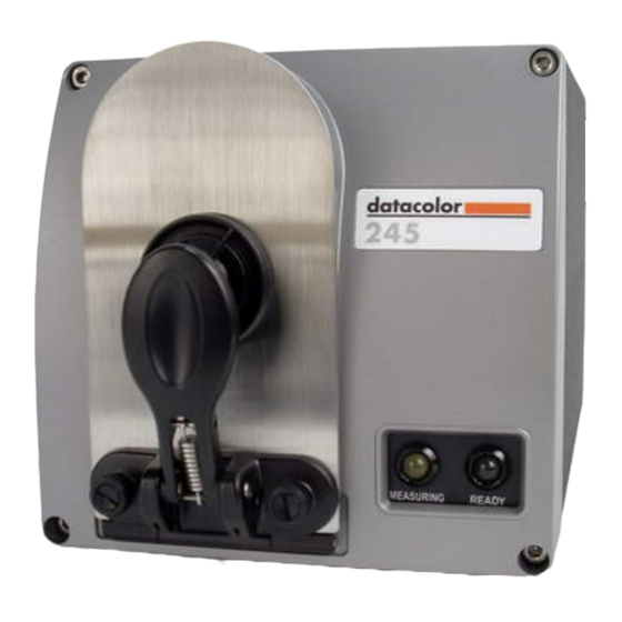
Datacolor 245™ About the Datacolor 245™ The Datacolor 245 provides a new, solid-state approach to 45º/0º measurement geometry. It employs a unique, dual-beam optical design, uses a pulsed xenon lamp and has a sealed optical path for improved repeatability and long-term stability. 45º/0º instruments are used for quality control applications when both color and appearance features are being evaluated. -
Page 6: Electrical And Environmental Requirements
VOLTAGE COMPONENTS WITHIN. DO NOT INSERT ANY OBJECTS INTO THESE OPENINGS! Feature Summary The Dataflash is one of a family of Datacolor instruments that employs state-of-the-art features including the spectrometer, light source, and optics. Below is a summary of those features: FEATURE... -
Page 7: Accessories
The serial number on the back of the white calibration standard should match the serial number on the instrument. Aperture Plates The Datacolor 245 is a single aperture instrument. Refer to Appendix, Features by Model for the aperture specification. Accessories • 3... - Page 8 This page intentionally left blank. 4 • Accessories Datacolor 245™ User's Guide...
-
Page 9: Cable Installation
BE SURE TO TURN OFF THE POWER BEFORE WORKING WITH ANY CABLES. The Datacolor 245 requires the use of two cables, a power cable and either a serial cable or a USB cable, to connect the instrument to the computer. -
Page 10: Communications Cable
You may need to enter this information into the program. See USB Driver Installation in this guide for detailed instructions regarding the software installation. See the Appendix for a description of the RS-232C connector pin assignments. 6 • Cable Installation Datacolor 245™ User's Guide... -
Page 11: Usb Driver Installation
When this connection is made, the system detects a new piece of hardware, and the screen below automatically appears: The New Hardware Wizard automatically replaces this screen. 3. Click Next to continue with the USB driver installation. Cable Installation • 7 Datacolor 245™ User's Guide... - Page 12 If the driver software is in a different location click Browse, and identify the correct location. − If the correct location is identified, click OK. The program will search for the driver file. When the correct file is found, the window below appears: 8 • Cable Installation Datacolor 245™ User's Guide...
- Page 13 Click Next. The Wizard will begin copying the files to the computer. 6. When the copy is complete, the window below appears: Cable Installation • 9 Datacolor 245™ User's Guide...
- Page 14 7. Click Finish. Do not remove the USB Driver CD from the drive. The Wizard will close, and then immediately reopen and repeat the procedure. You must complete it a second time to successfully copy the file. 8. Click Next. 9. Click Next. 10 • Cable Installation Datacolor 245™ User's Guide...
- Page 15 Browse button, and locate the CD drive on your system. 12. Click Next. The Wizard will begin copying the files to the computer. When the copy is completed, the window below appears: 13. Click Finish. Cable Installation • 11 Datacolor 245™ User's Guide...
-
Page 16: Viewing/Changing System Port Assignment
As part of this process, a port number is assigned to the USB port. The default selection is the next available com port. Depending on the application you are running, you may need to know this port assignment to configure the Datacolor applications program(s) to recognize the USB port. - Page 17 The Systems Properties dialog box displays. Cable Installation • 13 Datacolor 245™ User's Guide...
- Page 18 4. Click the Hardware Tab. 5. Click the Device Manager button. The Device Manager window displays. 6. Go to the Ports heading. Click on the plus (+) to display the port selections. 14 • Cable Installation Datacolor 245™ User's Guide...
- Page 19 7. Click USB Serial Port. The USB Serial Port (COM3) Properties dialog box displays. 8. Click Port Settings. The dialog box below appears: Cable Installation • 15 Datacolor 245™ User's Guide...
-
Page 20: Changing The Com Port Assignment In Datacolor Programs
To enable the USB port for color measurements, you may need to change the com port assignment in the applications program. Refer to the program documentation for the specific Datacolor applications program you are running for instructions to configure the instrument. -
Page 21: Controls And Indicators
Controls and Indicators Status Panel The status panel indicates the current instrument settings being used. Below is the status panel for the Datacolor 245™: OPTION DESCRIPTION Measuring Instrument is making a measurement. Do not remove the sample from the port when this indicator is lit. -
Page 22: Powering Up
5. Launch a Datacolor program. Instrument Calibration The instrument should be calibrated every 8 hours to compensate for changes in the environment. A black trap, white tile and green tile are provided with all Datacolor instruments to complete the calibration: •... - Page 23 The software prompts for calibration vary from one program to another. The Datacolor Users Guide for the program you are running provides step-by-step instructions regarding the software setup and instrument calibration procedure. NOTE It is recommended that you calibrate the instrument every 8 hours.
- Page 24 This page intentionally left blank. 20 • Controls and Indicators Datacolor 245™ User's Guide...
-
Page 25: Sample Presentation And Measurement
The sample must completely cover the aperture opening. 1. Grasp the sample holder and pull forward. 2. Position the sample at the port. The sample should completely cover the port opening. Sample Presentation and Measurement • 21 Datacolor 245™ User's Guide... -
Page 26: Sample Viewing Port
When measuring small samples, you may need to check that the sample is properly positioned at the port. To verify that the correct area of the sample is being measured: 1. Grasp the tab above the aperture plate. 22 • Sample Presentation and Measurement Datacolor 245™ User's Guide... - Page 27 3. If necessary, adjust the placement of the sample to target the portion of the sample to be measured. The sample must completely cover the port opening. 4. Push the door back to its normal position, and start the measurement. Sample Presentation and Measurement • 23 Datacolor 245™ User's Guide...
- Page 28 This page intentionally left blank. 24 • Sample Presentation and Measurement Datacolor 245™ User's Guide...
-
Page 29: Maintenance
Use a few drops of the detergent solution to moisten a soft, lint-free cloth, and gently wipe the tile surface. Rinse the detergent from the tile by wiping it with a cloth, moistened with clean water. Maintenance • 25 Datacolor 245™ User's Guide... -
Page 30: Storage
Cleaning the Black Trap • The black trap should be kept dust-free. Dust accumulating in the black trap should be blown out with compressed air. 26 • Maintenance Datacolor 245™ User's Guide... -
Page 31: Appendix
Appendix Datacolor 245™ Optical Block Diagram Appendix • 27 Datacolor 245™ User's Guide... -
Page 32: Instrument Specifications
Metric Height 6.5 inches 165.1 mm Width 6.75 inches 171.5 mm Depth 12.375 inches 314 mm 14 lbs. 6.3 kg Weight * Specification based on following environmental conditions: 20°C; 50% RH; 2 sigma 28 • Appendix Datacolor 245™ User's Guide... -
Page 33: Miscellaneous Technical Information
Side Vents Vents are included along each side of the instrument to facilitate air circulation. HIGH VOLTAGE COMPONENTS WITHIN. DO NOT INSERT ANY OBJECTS INTO THESE OPENINGS! Appendix • 29 Datacolor 245™ User's Guide... -
Page 34: Compliance Statements
El present appareil numerique n’emet pas de bruits radioelectriques depassant les limites applicables aux appareils numeriques de la class A prescrites dans le Reglement sur le brouillage radioelectrique edicte par le ministere des Communications du Canada. • Index Datacolor 245™ User's Guide... -
Page 35: Index
COM Port Number, 16 Powering Up, 18 Compliance Statements, 30 RS-232C Connector Pin Assignments, Connecting to a USB Port Changing Com Port in Datacolor Sample, 22 programs, 16 Sample Presentation, 21 Changing System Port Assignment, 12 Serial cable, 3, 5...
Need help?
Do you have a question about the 245 and is the answer not in the manual?
Questions and answers