Starrett 2900 Series User Manual
Hide thumbs
Also See for 2900 Series:
- User manual (176 pages) ,
- User manual (12 pages) ,
- User manual (15 pages)
Table of Contents
Advertisement
Quick Links
Advertisement
Table of Contents

Related Manuals for Starrett 2900 Series


Summary of Contents for Starrett 2900 Series
- Page 1 1.800.544.2843 www.calcert.com sales@calcert.com...
- Page 2 READ THIS MANUAL BEFORE USING THE INSTRUMENT ANTES DE UTILIZAR EL INSTRUMENTO, LEA ATENTAMENTE ESTE MANUAL LIRE CE MANUEL AVANT D'UTILISER L'INSTRUMENT LEIA ATENTAMENTE ESTE MANUAL ANTES DE UTILIZAR O INSTRUMENTO 使用仪器前请阅读本操作手册 DIESES HANDBUCH VOR DER VERWENDUNG DES MESSGERÄTS LESEN LEGGERE ATTENTAMENTE QUESTO MANUALE PRIMA DI UTILIZZARE QUESTO STRUMENTO 10/17...
- Page 3 2900 INDICATOR CAPACITIVE SERIES PKG08803-UM2900 1.800.544.2843 www.calcert.com sales@calcert.com...
-
Page 4: Table Of Contents
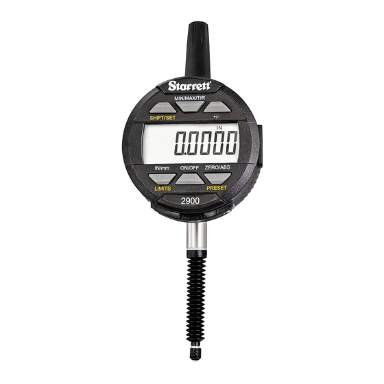
TABLE OF CONTENTS Components Cautions on Use Operating Instructions New Battery Startup Sequence New Zero Sequence Decription of the Button Functions Setting Presets Setting the Limits (Go/No Go Function) Setting the MIN/MAX/TIR Function Data Output Data Cover Removal Data Cable Attachment Battery Drawer Removal Battery Installation and Replacement Accessories... - Page 5 COMPONENTS Stem Cap Data Output Cover - Tapa del vástago - Cubierta de la salida de datos - Chapeau de canon - Couvercle de la sortie de données - Tampa da haste - Tampa da saída de dados - 主杆盖 - 数据输出盖...
- Page 6 2900 INDICATOR CAPACITIVE SERIES THIS IS A STARRETT USER GUIDE FOR THE 2900 INDICATOR CAPACITIVE SERIES. ALL SPECIFICATIONS IN THIS DOCUMENT ARE CORRECT AT TIME OF PRODUCTION AND ARE SUBJECT TO CHANGE. PLEASE CONTACT STARRETT FOR FURTHER INFORMATION. PKG08803-UM2900 1.800.544.2843 www.calcert.com...
-
Page 7: Cautions On Use
ENGLISH CAUTIONS ON USE 1. Avoid dropping the Indicator. 2. Avoid extreme temperatures, direct sunlight or below freezing for extended periods. 3. Avoid shocks to the contact point and spindle. Do not apply any radial force to the spindle. 4. If the indicator is stem-mounted, protect the indicator from being struck or bumped to prevent stem/case mechanical alignment damage. -
Page 8: Operating Instructions
ENGLISH OPERATING INSTRUCTIONS 1. First read the "New battery, Startup Sequence" section below, and the "Zero Sequence" on the next page 11. 2. Install the batteries that came with the indicator. Refer to "Battery Drawer Removal" and "Battery Replacement" on pages 25, 26. 3. -
Page 9: New Battery Startup Sequence
ENGLISH NEW BATTERY, STARTUP SEQUENCE 1. Each time you put in a new set of batteries, the indicator will go through a startup sequence. See "Battery Installation and Replacement" on pages 25, 26. At the end of the sequence you will need to move the spindle to initialize the measurement system. -
Page 10: New Zero Sequence
ENGLISH 3. When "Cal" is displayed, move the plunger slowly in and out, until the display changes to show the indicator measuring. This movement will calibrate the indicator. 4. This feature will happen each time the battery is replaced. 5. If you don't move the spindle, "Cal" will stay on the display for only 10 seconds and the display will go blank. - Page 11 ENGLISH 1-21/32" (42.2mm) 1/4" (6.4mm) 2-1/16" (52.8mm) 1/4" (6.4mm) CATALOG NO. RESOLUTION RANGE STEM DIA* 2900-3-1 .0005"/.01mm 1"/25 mm .375" Standard Features 2900-3M-25 .01mm 25 mm 8 mm 2900-5-1 .0005"/ .01mm 1"/25 mm .375" Advanced Features 2900-5M-25 .01mm 25 mm 8 mm 2900-3ME-25 .01mm /.0005"...
- Page 12 ENGLISH POWER REQUIREMENTS AND CURRENT CONSUMPTION 2 – CR2032 Lithium Coin Cells Battery Capacity 240 mAh Automatic Sleep Time 30 minutes of non-use SPC SERIAL OUTPUT 1 Space Character 2 Status characters indicating the operating mode • BLANK - Normal mode •...
- Page 13 ENGLISH Pin 2 Pin 4 SERIAL OUTPUT CONNECTOR Pin 1 GND signal return Pin 2 Serial Receive Data Input (RX/RQST) Pin 3 Serial Transmit Data Output (TX/DATA) Remote Zero – Special Order Only Pin 4 State Change High to Low Pin 1 Pin 3 SERIAL INPUT VOLTAGE LEVEL SPECIFICATION...
-
Page 14: Decription Of The Button Functions
ENGLISH 3 / 7 / 8 4 / 6 Fig. 9 DESCRIPTION OF THE BUTTON FUNCTIONS The functions printed in yellow; LIMITS and PRESET, are used in conjunction with the SHIFT/SET button also printed in yellow. To enable these functions press the SHIFT/SET button first. - Page 15 ENGLISH DESCRIPTION OF THE BUTTON FUNCTIONS (CONTINUED) 4. IN/mm - Toggles the display between English or Metric values. 5. SHIFT/SET - Dual function button used to enable the, Preset and the Limits (Go/No Go) function. When enabled the SET (S) icon will be displayed on the top left corner of the display.
-
Page 16: Setting Presets
ENGLISH SETTING PRESETS This function is not available with the basic type indicators. To set the value, follow the steps below: 1. Press and hold the ZERO/ABS button until the ABS icon appears in the upper right corner of the LCD Fig. 9. 2. - Page 17 ENGLISH SETTING PRESETS (CONTINUED) 4. To move from the PRESET (P) icon to a digit, Press the SHIFT/SET button. The flashing digit indicates that the digit is ready to be SET Fig. 11. Press the PRESET button to increment the value. To set the digit, Press the SHIFT/SET button.
-
Page 18: Setting The Limits (Go/No Go Function)
ENGLISH SETTING THE LIMITS (GO/NO GO FUNCTION) This function is only available with the advanced type indicators. 1. Select the units to be displayed. 2. Press the SHIFT/SET button. The SET icon will appear in the upper left corner Fig. 12. Fig. - Page 19 ENGLISH SETTING THE LIMITS (GO/NO GO FUNCTION) (CONTINUED) 4. Press the SHIFT/SET button. The LIMIT icon will flash on/off. 5. Adjust the spindle to the desired minimum value. 6. Press the SHIFT/SET button to capture the minimum value. The LIMIT icon will stop flashing. 7.
- Page 20 ENGLISH SETTING THE LIMITS (GO/NO GO FUNCTION) (CONTINUED) to enter into MIN. SHIFT / SET LIMITS Press then BUTTON BUTTON LIMIT mode. SHIFT / SET Press the LIMIT icon will flash on/off BUTTON Adjust the spindle to the value you want Fig.
-
Page 21: Setting The Min/Max/Tir Function
ENGLISH SETTING THE MIN/MAX/TIR FUNCTION The Min/Max/TIR function measures the maximum and the minimum measurement values and displays the difference or the range of deviation in the part you are measuring. NOTE: This function is only available with the advanced type indicators. - Page 22 ENGLISH 9. Move the part under the indicator to find the high spot. You will know because the value will not change. 10. Press the MIN/MAX/TIR button. The TIR icon will appear in the display, and the display will show the value of the TIR.
-
Page 23: Data Output
ENGLISH DATA OUTPUT Data Output Fig. 16 Cover Location DATA COVER REMOVAL The data cover can be removed using a small Phillips head screwdriver. When using a data cable, place the data cover somewhere you can easily find it. When you are done using the data cable, make sure you replace the data cover to protect the electronics from dust and liquids. -
Page 24: Data Cable Attachment
ENGLISH DATA CABLE ATTACHMENT Plug in and secure the cable using the Phillips head screws taken from the data cover. The orientation of the data cable plug can only be placed as shown in Fig. 18. Data Output Cover Fig. 18 Data Output Cover Screws Data Cable... -
Page 25: Battery Installation And Replacement
ENGLISH BATTERY INSTALLATION AND REPLACEMENT Remove the battery drawer then replace the two batteries with two-type CR2032 batteries negative side down. Slide the tray carefully into the indicator and secure with the two screws. Inside the tray, there is a reminder of the type of battery and their orientation. -
Page 26: Accessories
Special contact points are Spindle listed on the next page. Fig. 21 These backs, contact points and all of the available indicator accessories can Spindle Bellows be found in your Starrett catalog Contact Point PKG08803-UM2900 1.800.544.2843 www.calcert.com sales@calcert.com... - Page 27 ENGLISH AGD DIAL INDICATOR BACKS PART NUMBER DESCRIPTION PT06608-1 70770 Lug off center, #25 PT06608M 70776 Adjustable bracket, #25 PT24076 72483 Screw-type lug back 1/4-20 thread PT06608E 70772 Screw-type lug back 3/8-24 thread PT24075 72487 Screw-type lug back 1/4-28 thread PT06608F 70773 Post-type lug back, #25...
- Page 28 ENGLISH AGD DIAL INDICATOR SPECIAL CONTACT POINTS PART NUMBER EDP DESCRIPTION PT06632-10 70798 Contact Point, #10 PT06632-11 70799 Contact Point, #11 PT06632-12 70800 Contact Point, #12 PT06632-13 70801 Contact Point, #13 PT06632-14 70802 Contact Point, #14 PT06632-15 70803 Contact Point, #15 53916 Roller Contact Point 50153 Contact Point Set of 14 Points PT24728...
- Page 29 ENGLISH AGD DIAL INDICATOR SPECIAL CONTACT POINTS PART NUMBER EDP DESCRIPTION PT21697-1/2 64632 Contact Point Extension, 1/2" PT21697-1 64633 Contact Point Extension, 1" PT21697-2 64634 Contact Point Extension, 2" PT21697-3 64635 Contact Point Extension, 3" PT21697-4 64636 Contact Point Extension, 4" PKG08803-UM2900 1.800.544.2843 www.calcert.com...
Need help?
Do you have a question about the 2900 Series and is the answer not in the manual?
Questions and answers