Table of Contents
Advertisement
Quick Links
Advertisement
Table of Contents

Related Manuals for Bdcom S5864H


Summary of Contents for Bdcom S5864H
- Page 1 BDCOM S5864H Hardware Installation Manual...
-
Page 2: Table Of Contents
2.3.3 Cabinet Configuration ..................... 7 2.3.4 Power Requirements ....................8 2.4 Installation Tools and Device .................... 8 Chapter 3 Installing the BDCOM S5864H Switch ................9 3.1 Installation Flow of BDCOM S5864H ................9 3.2 Installing the Machine Box of the Switch ................9 3.2.1 Installing the Machine Box on the Desk .............. - Page 3 Table of Contents 3.3.5 Connecting 100/40GE Ethernet QSFP28 Optical Ports ......... 14 1.3.6 USB Interface ....................... 16 3.4 Checking After Installation ....................16 Chapter 4 Maintaining Switch ...................... 18 4.1 Opening the Machine Box ....................18 4.2 Closing Machine Box ...................... 19 Chapter 5 Hardware Fault Analysis .....................
-
Page 4: Chapter 1 Bdcom S5864H Introduction
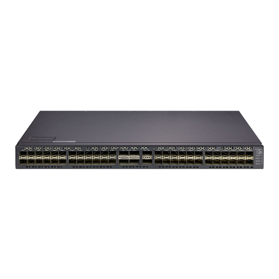
USB interface USB interface BDCOM S5864H has 4 hot swap fans and 2 two power sockets at its back. Figure 1-1 Front template of the BDCOM S5864H switch Table 1-2 Parts at the front template of the BDCOM S5864H switch Abbrev. -
Page 5: S5864H Systematic Characteristic Parameters
BDCOM S5864H Hardware Installation Manual Figure 1-2 Back template of the BDCOM S5864H switch Table 1-3 Parts at the back template of the BDCOM S5864H switch Abbrev. Name Description 1,3,9,11 Grounding column The grounding must be fine. POWER AC power supply AC220V, dual power backup, hot swap 2,10... - Page 6 BDCOM S5864H Hardware Installation Manual RFC 1157 SNMP v1/v2 Network management RFC 1213 MIB II standard RFC 1757 RMON 1,2,3,9 Flash Memory: 64M Bytes Memory SDRAM: 512Mbytes; 48 SFP+ 10GE optical ports; 4 QSFP28 100/40Gbps optical ports; 2 QSFP+ 40Gbps optical ports;...
-
Page 7: Rohs Description
BDCOM S5864H Hardware Installation Manual 1.3 ROHS Description - 4 -... -
Page 8: Chapter 2 Installation Preparation
Similar to other electronic products, the semiconductor chip easily gets damaged if you power on or off abruptly and frequently. To restart up the switch of BDCOM S5864H, you have to open the power on-off after the power is cut down for three to five seconds. -
Page 9: Safety Principles For Live Working
BDCOM S5864H Hardware Installation Manual Read the installation guide carefully before you operate the system. Only professionals are allowed to install or replace the switch. Pull out the AC power socket and close the direct-current power before operating on the machine box or working beside the power source. -
Page 10: Electrostatic Discharge Damage Prevention
BDCOM S5864H Hardware Installation Manual 2.2.4 Electrostatic Discharge Damage Prevention Electrostatic discharge may damage devices and circuits. Improper treatment may cause the switch to malfunction completely or discontinuously. Move or locate the devices according to the measures of electrostatic discharge prevention, ensuring the machine box connects the ground. -
Page 11: Power Requirements
2.4 Installation Tools and Device The tools and devices to install the BDCOM S5864H switch are not provided by the BDCOM S5864H switch. You yourself need to prepare them. The following are the tools and devices needed for the typical installation of the BDCOM S5864H switch: ... -
Page 12: Chapter 3 Installing The Bdcom S5864H Switch
Installing the machine box on the cabinet 3.2.1 Installing the Machine Box on the Desk The BDCOM S5864H switch can be directly put on the smooth and safe desk. Note: Do not put things weighing 4.5 kg or over 4.5 kg on the top of the switch. -
Page 13: Installing The Machine Box On The Cabinet
Figure 3-1. Figure 3-1 Fixing the machine box of the switch Caution: The switch shown in figure 3-1 does not represent the material S5864H. After the brackets are installed, install the switch on the cabinet. See Figure 3-2. - Page 14 9-hole plug (DB9). The RJ45 plug is put into the socket of the console port on the BDCOM S5864H switch. The inner line connection in the cable is shown in figure 3-1. The console cable is numbered as RLC0301.
-
Page 15: Connecting 10Ge Ethernet Sfp+ Ports
Figure 3-5 The inner connection of the 1-to-8 RJ45 cable (RLC0301) 3.3.2 Connecting 10GE Ethernet SFP+ Ports The BDCOM S5864H switch has 48 10GE SFP+ ports. Each port has its corresponding indicator: 1~48. You can connect the SFP+ optical module to the SFP+ port and then you can connect other Ethernet terminal devices through the optical cable. -
Page 16: Connecting 40Ge Ethernet Qsfp+ Ports
Ethernet terminals. Figure 3-8 Connecting the 1000Base-TX port and other Ethernet terminals Caution: The switch shown in figure 3-8 does not represent the material S5864H. Table 3-1 Pins of Gigabit RJ45 Pin Name... -
Page 17: Connecting 100/40Ge Ethernet Qsfp28 Optical Ports
Figure 3-10 Connecting the 40GE QSFP+ port (breaks out into 4 10GE ports) and other Ethernet terminals Caution: The switch shown in figure 3-9 does not represent the material S5864H. 3.3.5 Connecting 100/40GE Ethernet QSFP28 Optical Ports S5864H provides with 4 100/40GE QSFP28 ports. Each port has its corresponding indicator: 40G/100G 1~4. - Page 18 BDCOM S5864H Hardware Installation Manual In use, the four ports can be configured into three modes: 1. Set the rate of the port to 100Gbps You can connect the QSFP28 optical module to the optical port and then you can connect other Ethernet terminal devices with 100Gbps optical ports through the optical cable.
-
Page 19: Usb Interface
Figure 3-13 Connecting 100GE QSFP28 optical ports (configured to be 4 10GE ports) and other Ethernet terminals 1.3.6 USB Interface S5864H provides with 1 USB2.0 interface. Figure 3-14 Connecting USB2.0 interface 3.4 Checking After Installation Before electrically starting up the switch, perform the following checkups after the switch is installed: ... - Page 20 BDCOM S5864H Hardware Installation Manual Check whether the switch is correctly connected to other terminal devices. - 17 -...
-
Page 21: Chapter 4 Maintaining Switch
BDCOM S5864H Hardware Installation Manual Chapter 4 Maintaining Switch Caution: Before opening the machine box, make sure that you have released the static you carried and then turn off the power on-off of the switch. Before operating any step in Appendix B, read the section “Safety Advice”. -
Page 22: Closing Machine Box
BDCOM S5864H Hardware Installation Manual Caution: The switch shown in the above figure does not represent the material S5864H. When the cover is opened, put it aside. The mainboard of the system appears. Note: After taking off the cover, put it horizontally and avoid it to be crushed or collided. -
Page 23: Chapter 5 Hardware Fault Analysis
9600 bps, eight data bits, no sum check bit, one stop bit and no traffic control. 5.2 Indicator Description The LED indicator shows that the switch is running. The following table shows the indicators of the BDCOM S5864H switch and their description: - 20 -... - Page 24 BDCOM S5864H Hardware Installation Manual Abbrev. Name Description If the power supply A of the switch is PWRA Power indicator A powered on, the indicator is on. If the power supply B of the switch is PWRA Power indicator B powered on, the indicator is on.
- Page 25 BDCOM S5864H Hardware Installation Manual normally linked. If the indicator is off, the port is not linked. If the indicator flickers, there is data transmission. 2. working in the mode of 40GE If the indicator is always on, the port is normally lined.
- Page 26 BDCOM S5864H Hardware Installation Manual Figure 5-2 40GE BREAKOUT indicator Figure 5-3 QSFP+ port indicator - 23 -...
- Page 27 In no event shall BDCOM be responsible or liable, directly or indirectly, for any damage or loss caused or alleged to be caused by or in connection with the manual.
- Page 28 BDCOM S5864H Hardware Installation Manual BDCOM reserves the right to alter, update and otherwise change the information contained in the manual from time to time without notice. - 25 -...
Need help?
Do you have a question about the S5864H and is the answer not in the manual?
Questions and answers