Table of Contents
Advertisement
Quick Links
Advertisement
Table of Contents

Related Manuals for Bdcom P3310B


Summary of Contents for Bdcom P3310B
- Page 1 BDCOM P3310B EPON Installation Manual...
-
Page 2: Table Of Contents
Table of Contents Table of Contents Chapter 1 Introduction of BDCOM P3310B EPON Access Device ..................1 1.1 Standard Configuration............................1 1.2 Attribute Parameters of BDCOM P3310B EPON ....................4 1.3 ROHS Description ..............................5 Chapter 2 Installation Preparation ............................6 2.1 Cautions ................................ -
Page 3: Chapter 1 Introduction Of Bdcom P3310B Epon Access Device
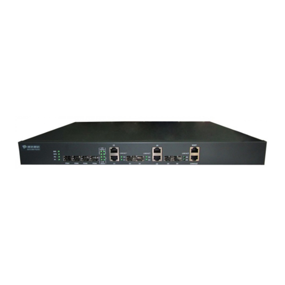
EPON and gives an overview of BDCOM P3310B EPON. 1.1 Standard Configuration BDCOM P3310B EPON has 4 EPON SFP ports, 2 GE optical/electric combo ports, 2 GE RJ45 electric ports, 2 GE SFP optical ports, 1 console port and 1 GE network management port. - Page 4 BDCOM P3310B EPON Installation Manual works normally. When PWR2 supplies power, this LED LED of power source 2 is on. When PWR1 supplies power, this LED LED of power source 1 is on. PON1,PON2, Gigabit OLT PON port Realizes the access of EPON ONU.
- Page 5 Network management Realizes the upgrade of the EPON MGMT port access device. Figure 1-2 Back faceplate of BDCOM P3310B EPON Table1-3 Parts at the Rear Faceplate of BDCOM P3310B EPON Access Device Abbrev. Name Remarks None AC power socket AC100-240V...
-
Page 6: Attribute Parameters Of Bdcom P3310B Epon
BDCOM P3310B EPON Installation Manual power socket backup power 1.2 Attribute Parameters of BDCOM P3310B EPON IEEE 802.1d Spanning Tree Protocol IEEE 802.1p Class of Service IEEE 802.1q tagged VLAN Protocol standard IEEE 802.3x Flow control IEEE 802.3ad Link aggregation IEEE 802.3ah Ethernet in the First Mile Task Force... -
Page 7: Rohs Description
BDCOM P3310B EPON Installation Manual 1.3 ROHS Description - 5 -... -
Page 8: Chapter 2 Installation Preparation
Similar to other electronic products, the semiconductor chip easily gets damaged if you power on and off abruptly and frequently. To restart up the switch of BDCOM P3310B EPON, you have to open the power on-off three or five seconds after the power is cut off. -
Page 9: Safety Principles For Live Working
BDCOM P3310B EPON Installation Manual Only professionals are allowed to install or replace the EPON access device. Pull out the AC power socket and close the direct-current power before operating on the chassis or working beside the power source. The final configuration of products must comply with relative national laws and regulations. -
Page 10: Electrostatic Discharge Prevention
BDCOM P3310B EPON Installation Manual 2.2.4 Electrostatic Discharge Prevention Electrostatic discharge may damage devices and circuits. Improper treatment may cause this device to malfunction completely or discontinuously. Move or locate the devices according to the measures of electrostatic discharge prevention, ensuring the chassis connects the ground. Another measure is to wear the static-proof hand ring. -
Page 11: Power Requirements
2.4 Installation Tools and Device The tools and devices to install BDCOM P3310B EPON are not provided by the BDCOM P3310B EPON. You yourself need to prepare them. The following are the... -
Page 12: Chapter 3 Installing Bdcom P3310B Epon Device
3.1 Installation Flow of BDCOM P3310B EPON Installing the Machine Box of BDCOM P3310B EPON The machine box of BDCOM P3310B EPON can be installed on the desk or can be fixed to other cabinets. Your network installation requirements can be met if you conduct the operations according to the following procedure. -
Page 13: Installing The Machine Box On The Desk
Installing the Machine Box on the Desk BDCOM P3310B EPON can be directly put on the smooth and safe desk. Note: Do not put items with more than 4.5kg on BDCOM P3310BEPON, or it will be damaged. 3.2.2 Installing the Chassis on the Cabinet The machine box of BDCOM P3310B EPON is fixed on the cabinet through the brackets. - Page 14 RJ45 plug. After you connect the console port to the serial port of PC through a console cable, you can configure and monitor BDCOM P3310B EPON by running a terminal emulation software, such as super Windows terminal. The cable is provided according to the host.
-
Page 15: Connecting The Epon Sfp Interface
One end of the cable is a 8-pin RJ45 plug and the other end is a 9-hole plug (DB9). The RJ45 plug is put into the socket of the console port on BDCOM P3310B EPON. The inner line connection in the cable is shown in figure 3-1. The console cable is numbered as RLC0301. -
Page 16: Connecting Ethernet-1000M Optical Port
3.3.3 Connecting Ethernet-1000M Optical Port BDCOM P3310B EPON provides four 1000M optical SFP ports. Each port has a corresponding indicator for showing the LINK/ACT state of the port. If the indicator is always on, the port is normally linked; if the indicator flickers, the data is forwarded through the port. - Page 17 Figure 3-9 RJ-45 connector of the console port Because 4 1000Base-T ports of BDCOM P3310B EPON support the MDI/MDIX auto-identification of the cable, BDCOM P3310B EPON can adopt five classes of direct-through/cross network cables when it connects other Ethernet terminals.
-
Page 18: Checking After Installation
Ethernet devices. 3.4 Checking After Installation After BDCOM P3310B EPON is installed, please conduct the following checkups before it is powered. If the EPON access device is installed on the cabinet, check whether the installation point between the cabinet and the EPON access device is strong. -
Page 19: Chapter 4 Maintaining The Epon Access Device
BDCOM P3310B EPON Installation Manual Chapter 4 Maintaining the EPON Access Device Caution: Before opening the chassis, make sure that you have released the static you carried and then turn off the power on-off of the EPON access device. Before operating any step in Appendix B, read the section “Safety Advice”. -
Page 20: Closing Chassis
BDCOM P3310B EPON Installation Manual Note: After taking off the cover, put it horizontally and avoid it to be crushed or collided. Otherwise, the chassis is hard to install. 4.2 Closing Chassis The section mainly describes how to put the cover and close the chassis. Do as... -
Page 21: Chapter 5 Hardware Fault Analysis
5.2 Indicator Description The LEDs are used to show what operations are conducted by the EPON access device. For the LEDs of BDCOM P3310B EPON and their description, see the following table: Abbrev. - Page 22 BDCOM P3310B EPON Installation Manual If the indicator is always on, the system is being started. System indicator If the indicator flickers, the system works normally. If the indicator is always on, the link on the port is normal. None...
Need help?
Do you have a question about the P3310B and is the answer not in the manual?
Questions and answers