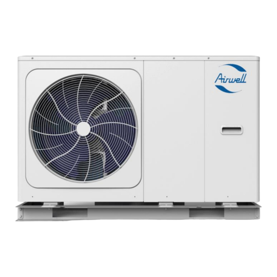
Summary of Contents for Airwell AW-WHPMA04-91
- Page 1 Airwell Typical Installation with Third Party controls Installation and Setup Monobloc system Rev 1.3 March 29 2022 Draft for Comments...
- Page 2 This manual is designed to be a quick start guide for the most common type of installation, for the Airwell Monobloc range. This shows heating via Buffer Tank and domestic hot water via a cylinder, with a sensor pocket and immersion heater installed, using 1x 3 port drive open valve to control space heating and Hot water heating demand using the Airwell controller and third-party control for the end user control.
-
Page 3: Warranty
Biocide, if not included in the heat transfer solution. • A 25lt buffer is Recommended for the 4-10kw units and a 40lt for the 12-16kw Airwell heat pumps, In order to meet the minimum system water open volume at all times. •... -
Page 4: Power Supplies
Power Supplies The Monobloc requires one Power supply, the details of the power supply are detailed below. Unit 10kW 12kW 14kW 16kW 12kW 3-PH 14kW 3-PH 16kW 3-PH Maximum overcurrent protector(MOP)(A) 8.0* 8.0* 10.0* 10.0* 10.0* 4.0* 4.0* 4.0* 4.0* 4.0* Wiring size(mm *The above sizing are for guidance only, correct cable sizing should be undertaken by a suitably qualified engineer. -
Page 5: Control Wiring
Control Wiring Below shows a basic wiring schematic for use with the previous hydralic schematic, for the Airwell monobloc Heat pump. Using a Third party room stat for switching on and off the heating demand. Each terminal supplies a maximum of 0.2amp if the item connected draws more than 0.2amp a relay and a external power supply should be used. -
Page 6: Dip Switch Settings
S4 Dip Switched are for multiple unit setups. S1 Dip switch 1/2 should be set to OFF/OFF, this will deactivate the IBH (internal back up heater is not fitted to the Airwell unit as standard) S1 Dip switch 3/4 should be set to... -
Page 7: Pre-Commissioning Checks
Pre-Commissioning Checks Before starting the unit, a number of pre checks that must be carried out. These can be found listed below. On the larger 12/14/16kw units there is a Transportation support bracket installed to the compressor within the unit, this bracket must be removed prior to starting the unit. - Page 8 Starting Up the Unit for the First Time When the monobloc is powered up for the first time, 1-100% will be displayed on the user interface during initialisation, in this time the controller can’t be used. The following setting must be entered into the controller these are detailed below, in order for the controller and Heat pump to operate correctly.
-
Page 9: Test Mode
Set T4H2 , set to c ֯ This will give a weather compensated curve of 45 degrees flow temp 2 degrees outside and a Flow temp of 30 degrees at 1 degrees outside ambient air temprture All change s to selections must be confirme with Press Back lect Room Thermostat... -
Page 10: Factory Reset
Once in Test Run menu, scroll down and select Air Purge with the unit will now run-in air purge Mode until exited. During this process any auto air vent within the unit should be open and any external auto air vent, the pressure should be observed throughout, the venting process and topped up as required. - Page 11 Putting the unit into Operations In order to put the unit into operation you must turn on the modes within the home screen. This is done by selecting the mode (highlighting on the main screen) and then by pressing the ON/OFF button to enable. ON/OFF DHW Mode DHW Mode...
-
Page 12: Fault Codes
3. Scroll through and check the minimum flow rate for the unit fitted is been achieved adjust the flow setter if required. Unit Minimum Flow Maximum Flow OPERATION PARAMETER Rate Rate GAS BOILER AW-WHPMA04-91 6.64 Lpm* 0.40 m³h* 14.16 Lpm 0.85 m³h AW-WHPMA06-91 6.64 Lpm* 0.40 m³h* 20.82 Lpm 1.25 m³h... - Page 13 Hydronic box EEPROM error DC generatrix voltage is too low Communication error between outdoor unit main control chip and hydronic box main control chip Communication error between outdoor unit main control chip and inverter driver chip Water side heat exchanger refrigerant outlet (liquid pipe) temperature sensor error Water side heat exchanger refrigerant inlet (gas pipe) temperature sensor error Inverter module protection (L0/L1 appear 3 times in one hour) Room temperature sensor Ta error...
- Page 14 Please find below the product MCS Certification numbers. If further details on the Unit’s SCOP values are required at the designed flow temp, these can be found at Product directory - MCS (mcscertified.com) searching the Certificate number below. Unit MCS Certified Product AW-WHPMA04-91 041-K015-01C AW-WHPMA06-91 041-K015-01D AW-WHPMA08-91 041-K015-02C...


Need help?
Do you have a question about the AW-WHPMA04-91 and is the answer not in the manual?
Questions and answers