Table of Contents
Advertisement
Advertisement
Table of Contents

Related Manuals for Airwell AWWR-WDF009-C11


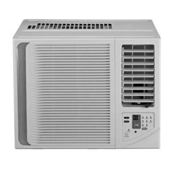
Summary of Contents for Airwell AWWR-WDF009-C11
- Page 1 PRECAUTION Window WDF Series Models: AWWR-WDF009-C11 AWWR-WDF012-C11...
-
Page 2: Table Of Contents
CONTENTS CONTENTS 1.1 Safety Precaution............................1 1.2 Warning ............................... 1 2. Specification..............................6 3. Dimension..............................7 4. Function and control panel......................... 8 4.1 Function..............................8 4.2 Control panel.............................. 8 5. -
Page 3: Safety Precaution
PRECAUTION 1. Precaution 1.1 Safety Precaution. To prevent injury to the user or other people and property damage, the following instructions must be followed. Incorrect operation due to ignoring instruction will cause harm or damage. Before service unit, be sure to read this service manual at first. 1.2 Warning Installation Do not use a defective or underrated circuit breaker. - Page 4 PRECAUTION and evaporator. For installation, always contact the dealer or an Authorized service center. There is risk of fire, electric shock, explosion, or injury. Do not install the product on a defective installation stand. It may cause injury, accident, or damage to the product. Be sure the installation area does not deteriorate with age.
- Page 5 PRECAUTION the power supply cable. There is risk of electric shock or fire. Stop operation and close the window in storm or hurricane. If possible, remove the product from the window before the hurricane arrives. There is risk of property damage, failure of product, or electric shock. Do not open the inlet grill of the product during operation.
- Page 6 PRECAUTION Use two or more people to lift and transport the product. Avoid personal injury. Do not install the product where it will be exposed to sea wind (salt spray) directly. It may cause corrosion on the product. Corrosion, particularly on the condenser and evaporator fins, could cause product malfunction or inefficient operation.
- Page 7 PRECAUTION There is risk of fire or explosion. Do not recharge or disassemble the batteries. Do not dispose of batteries in a fire. They may burn of explode. If the liquid from the batteries gets onto your skin or clothes, wash it well with clean water. Do not use the remote of the batteries have leaked.
-
Page 8: Specification
PRECAUTION 2. Specification. Model AWWR-WDF009-C11 AWWR-WDF012-C11 Characteristics Units Cooling Cooling Capacity Pdesign SEER Energy efficiency class Annual energy consumption Power supply V/Ph/Hz 220-240V/Single/50Hz 220-240V/Single/50Hz Circuit breaker rating 25,1 Fan type & quantity Cross flow fan x1 Cross flow fan x1... -
Page 9: Dimension
DIMENSION 3. Dimension. Window WDF Version - 0... -
Page 10: Function And Control Panel
FUNCTION AND CONTROL PANEL 4. Function and control panel. 4.1 Function. ※Operation mode: Cooling, Fan,Dry. ※Fresh air switch. ※LED display ※Sleep mode ※Swing function. ※Self-diagnosis function ※Timer function. ※Anti-freezing control in cooling mode or drying mode. Prevent the water being freezed on evaporator by sensing the evaporator pipe temperature in cooling mode. - Page 11 FUNCTION AND CONTROL PANEL 2】SWING BUTTON Press the “SWING” keypad(for the models with swing feature only) to activate the automatic air swing feature. To stop the air swing feature, press the “SWING” keypad again. Press the “SWING” keypad for 2 seconds will activate the SLEEP mode which can reduce noise creating a comfortable sleeping.
-
Page 12: Refrigerant Cycle Diagram
FUNCTION AND CONTROL PANEL 5. Refrigerant Cycle Diagram. The figure below is a brief description of the important components and their function in what is called the refrigeration system. This will help to understand the refrigeration cycle and the flow of the refrigerant in the cooling cycle. F o r o n ly c o o lin g C A P I L I A R Y T U B E L I Q U I D S I D E... -
Page 13: Wiring Diagram
WIRING DIAGRAM 6. Wiring Diagram Window WDF Version - 0... -
Page 14: Protection Function
PROTECTION FUNCTION 7. Protection Function. 7.1 Proper symbols and their meaning T1: Indoor ambient temperature T2: Indoor evaporator temperature T3: Outdoor condenser temperature Ts: Setting temperature through the remote controller 7.2 Protection Function 7.2.1 Three minutes delay at restart for compressor. 7.2.2 Anti-freezing protection at cooling or dry mode. -
Page 15: Electronic Function
PROTECTION FUNCTION The compressor and fan motor will be OFF Note: The Defect display can be cancelled only by pressing the ON/OFF button on the unit or the remote controller. Operation conditon 7.2.4 Electronic (T1-Ts) ℉ compressor on function. 7.2.4.1 Cooling mode speed... -
Page 16: Temperature Sensor Is Open Circuit Or Short Circuit
PROTECTION FUNCTION ΔT=T1-Ts Running mode ΔT>2℃ Cooling -1≤ΔT≤2℃ Fan-only The machine will choose actual running mode in auto mode in the below cases: Power on or change mode to auto mode or adjust temperature in auto mode, the machine will choose actual running mode again. -
Page 17: Installation Details
INSTALLATION 8 Installation details 8.1 Select the best location. 1. To avoid vibration and noise, make sure the unit is installed securely and firmly. 2. Install the unit where the sunlight does not shine directly on the unit. If the unit receives. direct sunlight, build an awning to shade the cabinet. -
Page 18: Check Off Installation
INSTALLATIOIN 8.2 Check off installation. The setting conditions must be checked prior to initial starting. The under mentioned items are especially important checking points when the installation is finished. Grounding wire (yellow/Green) is provided in the power cord. The wire must be grounded. Ensure that the unit is connected to a suitably rated and dedicated circuit. -
Page 19: How To Install
INSTALLATION 8.4 How to install. 1) Remove the sticker from the front panel. 2) Put the unit into the installation hole. When installing the unit, it should be slanted down to the back to avoid the enlargement of noise or vibration.(Slant between 6-10mm.) The installation place should be strong enough to avoid the enlargement of noise... - Page 20 INSTALLATIOIN Window WDF Version - 0...
-
Page 21: Characteristic Of Temperature Sensor
CHARACTERISTIC OF TEMPERATURE SENSOR 10 Characteristic of temperature sensor. Temp.℃ Resistance KΩ Temp.℃ Resistance KΩ Temp.℃ Resistance KΩ 62.2756 14.6181 4.3874 58.7079 13.918 4.2126 56.3694 13.2631 4.0459 52.2438 12.6431 3.8867 49.3161 12.0561 3.7348 46.5725 11.5 3.5896 10.9731 3.451 41.5878 10.4736 3.3185 39.8239 3.1918... -
Page 22: Troubleshooting
TROUBLESHOOTING 11 Troubleshooting In general, possible trouble is classified in three kinds. One is called Starting Failure which is caused from an electrical defect, another is ineffective Air Conditioning caused by a defect in the refrigeration circuit and improper application, and the other is called the Structure Damage. Operation panel don't work. - Page 23 TROUBLESHOOTING The air-con doesn't work. Check the power supply. Check the wiring. Check whether the transformer is failed. Measure the output voltage of transformer and check whether it is the range from +5V to 12V. If not, replace the transformer. Replace the PCB.
- Page 24 TROUBLESHOOTING Display keeps showing "Ed". Check whether the evaporator frosts. Check whether the indoor air inlet is blocked. Check whether the indoor ambient temperature is too low. Check whether the indoor dust filter is too dirty. Check whether there is too much water on the chassis. Check the wiring of pipe temperature sensor.
- Page 25 TROUBLESHOOTING Compressor doesn't work. Check whether the indoor temperature is lower than 15° C or larger than 31° C. Check the power supply. Check whether the voltage is too high or too low. Check the wiring. Check whether the compressor is under overload protection. Check the relay of compressor in PCB works normally.
- Page 26 TROUBLESHOOTING Cooling mode don't work or cooling not enough. Check the operation mode. Check the setting temperature. Check whether dust filter is too dirty. Start the unit with cooling mode, check whether the temperature of the compressor's discharge pipe is smaller than 90 ℃ , if no, recharge refrigerant. Replace the capillary.
- Page 27 TROUBLESHOOTING The compressor operates run-stop frequently. Check whether the airflow passage is blocked. Check whether the fan motor doesn't work. Check whether capacitor of compressor work normally. Check whether the relay of compressor on PCB works normally. Replace the PCB. Check whether the capillary is blocked.
- Page 28 TROUBLESHOOTING Water drips from the unit. Check whether the ambient humidity is too high. Check whether the indoor outlet airflow foam is too wet, and louver drip. Check whether the unit is correctly installed. Check whether the air outlet foam install normally. Check whether the foam of evaporator base is damaged.
- Page 29 TROUBLESHOOTING : For reverse cycle model No/ineffective cooling No/ineffective heating Er…indicates room temp. sensor failure Whether the display panel En indicates indoor pipe sensor failure display one of the following Eo indicates outdoor pipe sensor failure signal? "Er En Eo Ed" Ed indicates that the evap.
-
Page 30: Exploded View And Part List
EXPLODED VIEW AND PART LIST 12 Exploded view and part list AWWR-WDF009-C11 Window WDF Version - 0... - Page 31 EXPLODED VIEW AND PART LIST Part list: Part Name Part Name Panel assembly Chassis assembly Front panel Evaporator base Air filter Cabinet assembly Panel frame Ventilation ring 1.3.1 Panel frame Volute shell (below) 1.3.2 Horizontal louver Evaporator coil assembly Air outlet assembly Compressor Remote controller Suction pipe assembly...
- Page 32 EXPLODED VIEW AND PART LIST AWWR-WDF012-C11 Window WDF Version - 0...
- Page 33 EXPLODED VIEW AND PART LIST Part list: Part Name Part Name Panel assembly Drain stopper Front panel Cabinet assembly Air filter Rear separating Panel frame Axial flow fan Horizontal louver Asynchronous motor Air outlet assembly Supporter assembly of fan motor Remote controller Front separating board Display box assembly...
- Page 35 SERVICE MANUAL Window WDF Series Window WDF Version - 0...
Need help?
Do you have a question about the AWWR-WDF009-C11 and is the answer not in the manual?
Questions and answers