
Subscribe to Our Youtube Channel
Related Manuals for THERMOSTAHL ENERDENSE


Summary of Contents for THERMOSTAHL ENERDENSE
- Page 1 GAS/LIQUID FUELED STEEL BOILER ENERDENSE INSTALLATION AND SERVICE MANUAL VERSION: UPDATE: 12.04.2022...
-
Page 2: Table Of Contents
Contents GENERAL INFORMATION ................... 3 1.1. Proper use of the appliance ................3 1.2. Safety warnings ....................3 1.3. Data label ......................3 1.4. Document information ..................3 TECHNICAL FEATURES AND DIMENSIONS ............4 2.1. Technical features ..................... 4 2.2. Function principle .................... -
Page 3: General Information
The appliance is designed for use in pumped hot water central heating systems. Any other use is considered improper and is prohibited. THERMOSTAHL declines any responsibility for damages or injuries caused by improper use; in this case the risk is completely at the user’s responsibility. -
Page 4: Technical Features And Dimensions
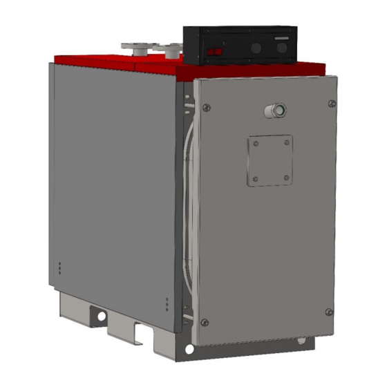
▪ Control panel for electromechanical operation (optional) 2.2. Function principle ENERDENSE is a high efficiency steel boiler with condensing heat exchanger, for function with liquid or gaseous fuel. The heat exchanger is made of special inox steel, with high corrosion resistance, which ensures optimal heat transfer from the exhaust gas to the water. -
Page 5: Working Medium
TECHNICAL FEATURES AND DIMENSIONS 2.3. Working medium The ENDS boiler is designed for function with water as working medium, with a maximum concentration in polypropylene glycose of 50%. The maximal temperature of the water is 95ºC. For condensing regim the return temperature must be maximum 35 C. -
Page 6: Dimensions
TECHNICAL FEATURES AND DIMENSIONS 2.4. Dimensions T1-T2 BOILER TYPE inch ENDS 125 1140 1100 1605 DN50 1” 1½” ENDS 200 1280 1350 1840 DN65 1” DN50 ENDS 300 1340 1500 2060 DN80 1” DN50 ENDS 400 1340 1800 2360 DN80 1”... -
Page 7: Fuel
BOILER MOUNTING 2.5. Fuel The ENDS is designed for function with the following fuels: 1. Natural Gas, according to DIN 4756 and 4788, with lower calorific power 10,0 kWh/Nm The delivery conditions of natural gas to the burner are stabilized by the Norm for natural gas I 6-98, for gas with low pressure (p=50mbar) 2. -
Page 8: Boiler Room
BOILER MOUNTING 3.2. Boiler room 3.2.1. General requirements The boiler must be installed in a special and separate room. This room must be chosen so that it offers easy access for fuel transport, air supply and exhaust gas evacuation. The doors of the boiler room must be metallic, open outwards, and have at least 0,9 m width. - Page 9 BOILER MOUNTING 3.2.2. Boiler room dimensions The boiler must be placed on a horizontal plane, with adequate mechanical resistance to support the boiler’s weight. The boiler must be positioned in the room in such a way so that it is easily accessible from all the sides. The following dimensions are recommended (see Fig 2): Distance from the front wall (N): For boilers up to 100 kW –...
-
Page 10: Chimney
BOILER MOUNTING 3.3. Chimney The appropriate chimney installation is very important for the boiler’s efficient and safe function! The chimney must be made of a material which is corrosion resistant to the condesate (plastic PP). The chimney must be positioned if possible in the interior of the building. It must be vertical, with no changes in the direction. -
Page 11: Mounting The Burner
BOILER MOUNTING 3.5. Mounting the burner The ENDS boilers are overpressure boilers and it is necessary to take into account the static pressure of counter-pressure in the combustion chamber to select the proper burner. The burner must be selected according to the furnace power and the counterpressure. Always refer to the burner manufacturer technical datasheet. -
Page 12: Mounting The Control Panel
BOILER MOUNTING Min burner Boiler type tube length ENDS 125 4 x M8 ENDS 200-400 8 x M10 ENDS 500-600 7 x M16 3.6. Mounting the control panel To mount the panel, fasten the clips on the respective holes in the boilers cover, as shown in the diagram. -
Page 13: Door Adjustment
BOILER MOUNTING 3.7. Door adjustment The boiler door can be adjusted in all three axes. To adjust horinzontally and vertically, gently losen the nuts and move the hinge into to oval hole. To adjust the depth, tighten the nut. You can also change the direction of the door by changing the hinge position. Lower the door, and change the position of the hinge and locking screw, as in diagram below. -
Page 14: Installation
INSTALLATION 4. INSTALLATION 4.1. Hydraulic connections Legend Boiler outet Boiler inlet - high temerature Boiler inlet - low temperature Chimney connection Drianage valve Safety connection Condensate draiange connection If a connection pipe is not used, it must be sealed before water fill! 4.2. -
Page 15: Safety Features
INSTALLATION 4.3. Safety features The boiler can be delivered as an optional with a safety kit, which shall be connected to the corresponding safety connection pipe. The kit consists of a safety valve, an air relief valve and a thermomanometer. Additional safety equipment can be mounted on the outlet line, at a distance less than 1,5 m from the boiler. -
Page 16: Connection Diagrams
INSTALLATION 4.5. Connection diagrams Legend Boiler Ball valve Expansion vessel Non-return valve Boiler safety kit Drain valve Heating circuit pump HUW pump Y-filter Chemical filter Automatic water fill valve Filling line Hot water boiler Dual safety valve pressre/temperature Heating installation – radiators Heating installation –... -
Page 17: Electrical Connections
16A. The boiler room lighting must be on a separate circuit. The user is obliged to connect the boiler to an efficient grounding system. THERMOSTAHL ROMANIA SRL declines any liability for damage caused to people, animals and goods, due to defects caused by faulty electrical connections or lack of connecting the boiler to an efficient grounding system. - Page 18 ELECTRICAL CONNECTIONS Fig 6. EN-1 control panel wiring diagram Legend: General ON/OFF switch 1,2,3 Electrical supply ~230V/50Hz Safety thermostat 4,5,6 Pump connection Burner thermostat Room thermostat connection Pump thermostat 9,10,11 Burner electrical supply General function lamp 12,13 Burner stage 1 Burner indication lamp stage 1 14,15 Burner stage 2...
-
Page 19: Boiler Start-Up
BOILER START-UP 6. BOILER START-UP 6.1. Initial lighting checks Before you start the boiler, make the following checks: ▪ Check that all the hydraulic connections and make sure they are tight. Make sure there is no leakage or moisture on the pipes or other equipment. ▪... -
Page 20: Combustion Regulation
BOILER START-UP 6.4. Combustion regulation The flame from the burner must be thin and longitudinal and should not reach the side walls of the fire chamber (nozzle projection angle=60º, possibly 45º for power over 140 Mcal/h). The loading of the boiler with an atomizer smaller than the one that corresponds to the normal heat value supply of the boiler is not recommended. -
Page 21: Service And Maintenance
SERVICE AND MAINTENANCE 7. SERVICE AND MAINTENANCE 7.1. Cleaning the boiler The boiler should be maintained and cleaned once a year. To clean the boiler follow the next steps: ▪ Switch off the main switch in the boiler panel. ▪ Disconnect the burner (if necessary). ▪... -
Page 22: Basic Service Procedures
SERVICE AND MAINTENANCE 7.3. Basic service procedures 7.3.1. Service after overheating If overheating occurs, the safety valves of the boiler must open. Make sure the boiler pump is working. In case of blackout, the burner will stop operation and the temperature will soon fall. Open some valves of the system if necessary to decrease the boiler temperature faster. - Page 23 RVICE AND MAINTEN THERMOSTAHL ROMANIA SISTEME TERMICE S.R.L. DRUMUL OSIEI 57-59, sector 6 Bucharest 062395, Romania www.thermostahl.ro...
Need help?
Do you have a question about the ENERDENSE and is the answer not in the manual?
Questions and answers