
Related Manuals for THERMOSTAHL ENP 20


Summary of Contents for THERMOSTAHL ENP 20
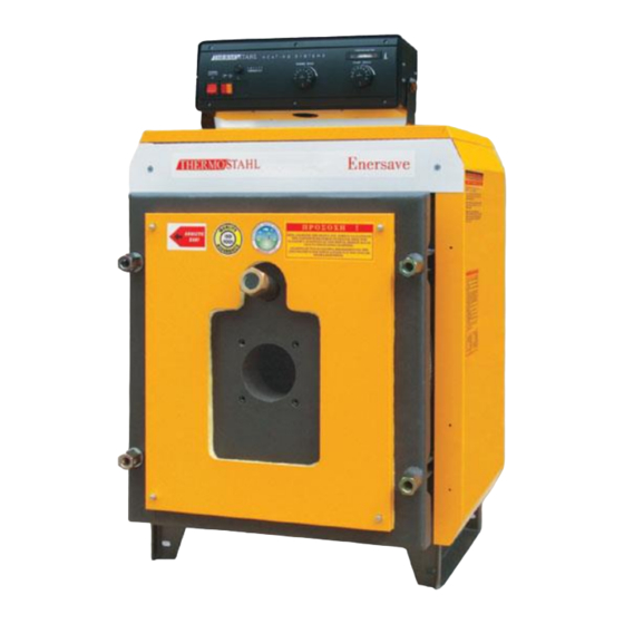
- Page 1 GAS/LIQUID FUELED STEEL BOILER ENERSAVE PLUS INSTALLATION AND SERVICE MANUAL VERSION: UPDATE: 02.03.2015...
-
Page 2: Table Of Contents
Contents GENERAL INFORMATION ................... 3 1.1. Proper use of the appliance ................3 1.2. Safety warnings ....................3 1.3. Data label ......................3 1.4. Document information ..................3 TECHNICAL FEATURES AND DIMENSIONS ............4 2.1. Technical features ..................... 4 2.2. Function principle .................... -
Page 3: General Information
The appliance is designed for use in pumped hot water central heating systems. Any other use is considered improper and is prohibited. THERMOSTAHL declines any responsibility for damages or injuries caused by improper use; in this case the risk is completely at the user’s responsibility. -
Page 4: Technical Features And Dimensions
Electrostatically painted external covers Control panel for electromechanical operation (optional) 2.2. Function principle ENP 20 – EN 300 EN 350 – EN 2500 Fig 1. Boiler function scheme The function of the boiler is based on the counter-pressure that is created by the returnable flame in the combustion chamber and by the transmission of heat with radiation. -
Page 5: Working Medium
TECHNICAL FEATURES AND DIMENSIONS The results a complete and perfect combustion with a small excess of air, and uniform heat charge of the surfaces. The door has an insulation cord to ensure air-tight closing. The door is equipped with a flange for burner mounting and an inspection eye for flame inspection. -
Page 6: Dimensions
TECHNICAL FEATURES AND DIMENSIONS 2.4. Dimensions ENP 20-160 T1-T2 Type inch inch inch ENP 20 1 ¼” ½” ½” ENP 30 1 ¼” ½” ½” ENP 40 1000 1 ¼” ½” ½” ENP 50 1100 1 ½” ½” ½” ENP 60 1050 1 ½”... - Page 7 TECHNICAL FEATURES AND DIMENSIONS ENP 180-2500 T1-T2 Type inch inch ENP 180 1040 1240 1050 1600 2 ½” 1” ENP 200 1040 1240 1050 1600 2 ½” 1” ENP 220 1040 1240 1300 1800 2 ½” 1” ENP 250 1040 1240 1300 1800...
- Page 8 Pressure Water Effici chamber Weight power pressure surface drop content ency volume Type (Δt=15 Mcal/h mm H ENP 20 2..4 91,5 ENP 30 2..4 91,5 ENP 40 2..4 91,5 ENP 50 2..4 91,5 ENP 60 4..6 91,5 ENP 70 4..6...
-
Page 9: Fuel
BOILER MOUNTING 2.5. Fuel The ENP is designed for function with the following fuels: 1. Natural Gas, according to DIN 4756 and 4788, with lower calorific power 8.500 kcal/Nm The delivery conditions of natural gas to the burner are stabilized by the Norm for natural gas I 6-98, for gas with low pressure (p=500 mmCA) 2. -
Page 10: Boiler Room
BOILER MOUNTING 3.2. Boiler room 3.2.1. General requirements The boiler must be installed in a special and separate room. This room must be chosen so that it offers easy access for fuel transport, air supply and exhaust gas evacuation. The doors of the boiler room must be metallic, open outwards, and have at least 0,9 m width. -
Page 11: Boiler Room Dimensions
BOILER MOUNTING 3.2.2. Boiler room dimensions The boiler must be placed on a horizontal plane, with adequate mechanical resistance to support the boiler’s weight. The boiler must be positioned in the room in such a way so that it is easily accessible from all the sides. The following dimensions are recommended (see Fig 3): Distance from the front wall (N): For boilers up to 100 kW –... -
Page 12: Chimney
BOILER MOUNTING 3.3. Chimney The chimney installation must supply sufficient draught, air tightness and protection against condensation. The appropriate chimney installation is very important for the boiler’s efficient and safe function! The chimney must be positioned if possible in the interior of the building. It must be vertical, with no changes in the direction. -
Page 13: Mounting The Burner
BOILER MOUNTING 3.4. Mounting the burner The ENP boilers are overpressure boilers and it is necessary to take into account the static pressure of counter-pressure in the combustion chamber to select the proper burner. The dimensions of the flange on the boiler door for mounting the burner as well as of the support screws are according to DIN 4789. -
Page 14: Burner Mounting Dimensions
(kW) D(Фmm) L1(mm) L2(mm) ENP 15 BFG1 H2 GAS X0 TL ENP 20 BFG1 H2 GAS X0 TL ENP 30 BFG1 H2, BFG1-2 H3 GAS X1 TL; GAS X1-2 TL ENP 40 BFG1 H2, BFG1-2 H3 GAS X1 TL; GAS X1-2 TL... -
Page 15: Installation
INSTALLATION 4. INSTALLATION 4.1. Hydraulic connections ENP 20-160 Legend Boiler outlet Boiler inlet Chimney connection Drainage valve Safety connection ENP 180-2500 Legend Boiler outlet Boiler inlet Chimney connection Drainage valve The boiler is intended for connection with a closed expansion vessel network. The boiler is intended for maximum working temperature 90 C and maximum pressure 3 bars. -
Page 16: Expansion Vessel
INSTALLATION Legend Burner Control panel Manometer Safety kit 5,7,8. Safety valve Air relief valve Drainage valve Ball valve 11,13,15. Pump One-way valve Expansion vessel 4.2. Expansion vessel The ENP boiler is recommended to be connected with closed expansion vessel. The volume of the expansion vessel is calculated according to the quantity of the water in the installation and the static height. -
Page 17: Safety Features
INSTALLATION 4.3. Safety features The boiler equipment includes a safety kit, which shall be connected to the corresponding safety connection pipe. The kit consists of a safety valve, an air relief valve and a thermomanometer. Additional safety equipment can be mounted on the outlet line, at a distance less than 1,5 m from the boiler. -
Page 18: Connection Diagrams
INSTALLATION 4.6. Connection diagrams 4.6.1. Central heating installation overview Legend Boiler Water filter Burner Radiators Burner filter Radiators valves Pump Expansion vessel Fuel tank Automatic water filler Water-level indicator Burner thermostat Tank ventilator Pump thermostat Tank alimentation 4-way mixing valve Tank plug Control panel Fuel valve for the burner... -
Page 19: Electrical Connections
16A. The boiler room lighting must be on a separate circuit. The user is obliged to connect the boiler to an efficient grounding system. THERMOSTAHL ROMANIA SRL declines any liability for damage caused to people, animals and goods, due to defects caused by faulty electrical connections or lack of connecting the boiler to an efficient grounding system. - Page 20 ELECTRICAL CONNECTIONS Fig 8. EN-1 control panel wiring diagram Legend: General ON/OFF switch Safety thermostat Burner thermostat Pump thermostat General function lamp Burner indication lamp Pump indication lamp Room thermostat Grounding Unscrew the control panel back plate to have access to the connection terminals in the interior. Connect the main electrical supply to the terminals 1, 2, 3 as indicated.
-
Page 21: En-2S Control Panel
ELECTRICAL CONNECTIONS 5.2.2. EN-2S control panel Legend: Thermometer Burner thermostat TR-1 Burner thermostat TR-2 Safety thermostat Pump thermostat General ON/OFF switch Burner indication lamp Pump indication lamp Fig 9. EN-2S control panel The general switch ON/OFF interrupts the electrical supply to all the devices. The burner thermostat TR-1 controls the stage-one function of the burner. - Page 22 ELECTRICAL CONNECTIONS Fig 10. EN-2S control panel wiring diagram Legend: General ON/OFF switch Safety thermostat TB-1 Burner thermostat-stage one TB-2 Burner thermostat-stage two Pump thermostat General function lamp Burner indication lamp Pump indication lamp Room thermostat Grounding Unscrew the control panel back plate to have access to the connection terminals in the interior. Connect the main electrical supply to the terminals 1, 2, 3 as indicated.
-
Page 23: Boiler Start-Up
BOILER START-UP 6. BOILER START-UP 6.1. Initial lighting checks Before you start the boiler, make the following checks: Check that all the hydraulic connections and make sure they are tight. Make sure there is no leakage or moisture on the pipes or other equipment. ... -
Page 24: Combustion Regulation
BOILER START-UP 6.4. Combustion regulation The flame from the burner must be thin and longitudinal and should not reach the side walls of the fire chamber (nozzle projection angle=60º, possibly 45º for power over 140 Mcal/h). The loading of the boiler with an atomizer smaller than the one that corresponds to the normal heat value supply of the boiler is not recommended. -
Page 25: Service And Maintenance
SERVICE AND MAINTENANCE 7. SERVICE AND MAINTENANCE 7.1. Cleaning the boiler The boiler should be maintained and cleaned once a year. To clean the boiler follow the next steps: Switch off the main switch in the boiler panel. Disconnect the burner (if necessary). ... -
Page 26: Maintenance After Long Stop
SERVICE AND MAINTENANCE Fig 12. Cleaning the chimney box 7.3. Maintenance after long stop It is necessary to perform a general maintenance and cleaning of the boiler after the heating season. Check the doors and the sealing cord. Make sure the contact with the boiler is air- tight. -
Page 27: Basic Service Procedures
TROUBLESHOOTING 7.4. Basic service procedures 7.4.1. Service after overheating If overheating occurs, the safety valves of the boiler must open. Make sure the boiler pump is working. In case of blackout, the burner will stop operation and the temperature will soon fall. Open some valves of the system if necessary to decrease the boiler temperature faster. -
Page 28: Warranty
WARRANTY 9. WARRANTY 1. Warranty duration is 3 years for all boiler parts under pressure, 1 year for other electro- mechanical equipment. The warranty period starts from the date of installation, but no longer than 120 days from the day of purchase. 2. - Page 29 THERMOSTAHL ROMANIA SISTEME TERMICE S.R.L. DRUMUL OSIEI 57-59, sector 6 Bucharest 062395, Romania www.thermostahl.ro...
Need help?
Do you have a question about the ENP 20 and is the answer not in the manual?
Questions and answers